PerfectView CAM 44 - Rear Camera DOMETIC - Free user manual and instructions
Find the device manual for free PerfectView CAM 44 DOMETIC in PDF.
Download the instructions for your Rear Camera in PDF format for free! Find your manual PerfectView CAM 44 - DOMETIC and take your electronic device back in hand. On this page are published all the documents necessary for the use of your device. PerfectView CAM 44 by DOMETIC.
USER MANUAL PerfectView CAM 44 DOMETIC
1 Explanation of symbols
2 Safety and installation instructions Please observe the prescribed safety instructions and stipulations from the vehicle manufacturer and service workshops. The manufacturer accepts no liability for damage in the following cases:
- Faulty assembly or connection
- Damage to the product resulting from mechanical influences and excess voltage
- Alterations to the product without express permission from the manufacturer
- Use for purposes other than those described in the operating manual Please observe the following instructions:
- To prevent short circuits, always disconnect the negative terminal of the vehicle’s electrical system before working on it. If the vehicle has an additional battery, its negative terminal should also be dis- connected.
- Insufficient supply line connections could result in short circuits which –Cause cable fires – Trigger the airbags – Damage electronic control devices – Cause electric functions to fail (indicators, brake light, horn, ignition, lights) WARNING! Safety instruction: Failure to observe this instruction can cause fatal or serious injury. CAUTION! Safety instruction: Failure to observe this instruction can lead to injury. NOTICE! Failure to observe this instruction can cause material damage and impair the function of the product. NOTE Supplementary information for operating the product. CAM44-IO-16s.book Seite 12 Mittwoch, 5. Oktober 2016 11:38 11EN CAM44 Safety and installation instructions
- When working on the following cables, only use insulated cable terminals, plugs and flat push-on receptacles: – 30 (direct supply from positive battery terminal) – 15 (connected positive terminal, behind the battery) – 31 (return cable from the battery, earth) – 58 (reversing light) Do not use terminal strips.
- Use a crimping tool (fig. 1 10, page 3) to connect the cables.
- Screw the cable for connections to cable 31 (earth) – Screw on the cable using a cable terminal and serrated washer to one of the vehicle's earth bolts or – Screw the cable to the bodywork using a cable terminal and a self-tapping screw Make sure there is a good earth connection. If you disconnect the negative terminal of the battery, the entire data stored in the volatile memories will be lost.
- The following data must be reset, depending on the vehicle equipment options: –Radio code – Vehicle clock –Timer – On-board computer – Seat position You can find instructions for making these settings in the corresponding operating manual. Observe the following installation instructions:
- Secure the parts of the camera installed in the vehicle in such a way that they cannot become loose under any circumstances (sudden braking, accidents) or cause injuries to the occupants of the vehicle.
- Secure any parts of the system covered by the bodywork in such a manner that they cannot be come loose or damage other parts and cables or impair vehicle functions (steering, pedals, etc).
- To prevent damage when drilling, make sure there is sufficient space on the other side for the drill head to come out (fig. 2, page 4).
- Always follow the safety instructions of the vehicle manufacturer. Some work (e.g. on retention systems such as the AIRBAG etc.) may only be performed by qualified specialists. Observe the following instructions when working with electrical parts:
- When testing the voltage in electrical cables, only use a diode test lamp (fig. 1 8, page 3) or a voltmeter (fig. 1 9, page 3). Test lamps with an illuminant (fig. 1 12, page 3) consume voltages that are too high and can damage the vehicle's electronic system.
- When making electrical connections, ensure that: – They are not kinked or twisted – They do not rub on edges – They are not laid through sharp-edged ducts without protection (fig. 3, page 4).
- Insulate all connections.
- Protect the cables from mechanical wear (for example rubbing against existing cables) using cable binders or insulating tape. The camera is watertight. However, the seals on the camera cannot withstand a high- pressure cleaner (fig. 4, page 4). Therefore, you should observe the following instructions when handling the camera:
- Do not open the camera, as this impairs the watertightness and the function of the camera (fig. 5, page 4).
- Do not pull on the cables, as this impairs the watertightness and the function of the camera (fig. 6, page 4).
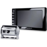
3Scope of delivery 4Accessories Available as accessory (not included in scope of delivery): 5 Intended use The CAM44 camera (item no. 9600000043) camera is designed primarily for use in vehicles. It can be used in rear view video systems to observe the space behind the vehicle from the driver's seat when manoeuvring or parking, for example.
No. infig. 8, page 5Quantity Description Ref. no.11Camera with motorised protective cover22Cover3 1 Camera guard4 1 Camera bracket5 1 Insulation pad6 1 CAM44 adapter box 91022000787 1 Extension cables 9102200030– 1 Fastening materialDescription Ref. no.AMP100 switch box 9600000210 WARNING! Since rear view systems are designed merely as an additional aid for reversing, they do not relieve you of the duty to take proper care when reversing. CAM44-IO-16s.book Seite 15 Mittwoch, 5. Oktober 2016 11:38 11EN Technical description CAM44
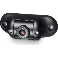
6 Technical description The colour camera with integrated microphone is encased in an aluminium housing and transmits image and sound to a monitor via a cable. It has a close-up lens and a long-range lens. The infrared LEDs improve night vision. The long-distance lens shows the space behind the vehicle as if you were looking through a rear window. You can switch it on when you are not reversing. The close-up lens (reversing camera) is a wide-angle lens, which shows the area directly behind the vehicle. It is activated when you engage reverse gear. The camera produces three distance marks in reversing mode which are shown on a connected colour monitor as coloured lines. The CAM44 camera is equipped with a motorised cover to protect against dirt.
The camera consists of the following elements: NOTE The cameras were equipped with a reverse display at the factory. Any monitor that is connected therefore needs a normal picture function. No. in fig. 9, page 5 Description1 6-pin connection cable2 Long-range lens3 Infrared LEDs4 Close-up lens (reversing camera)5 Microphone CAM44-IO-16s.book Seite 16 Mittwoch, 5. Oktober 2016 11:38 11EN CAM44 Notes on the electrical connections
7 Notes on the electrical connections
Please therefore observe the following instructions:
- As far as possible, use original openings or alternative openings for the connecting cable duct, e.g. the paneling edges, ventilation grilles or blank panels. If no openings are available, you must drill holes for the cables. Check beforehand that there is sufficient room for the drill head to come out on the other side.
- Wherever possible, lay cables inside the vehicle, as they are better protected there than outside. If you do need to lay a cable outside the vehicle, ensure that it is well fastened (use additional cable ties, insulating tape etc.).
- To prevent damage to the cables, when laying them, ensure that they are far enough away from hot or moving vehicle components (exhaust pipes, drive shafts, light systems, fans, heater etc.). Use corrugated piping or other protective materials to protect against mechanical wear.
- Screw on the plug connections of the connecting cables to protect against water penetration (fig. 0, page 5).
- When laying the cables, make sure: – They are not kinked or twisted – They do not rub on edges – They are not laid through sharp-edged ducts without protection (fig. 3, page 4).
- Attach the cables securely in the vehicles to prevent tripping hazards. Use cable binders, insulating tape or glue the cables in place. NOTICE! Risk of damage!
- To prevent damage, when drilling ensure that there is sufficient space on the other side for the drill head to come out.
- Cables and connections which are not properly installed will cause malfunctions or damage to components. Correct installation of cables and connections is the basic prerequisite for lasting and trouble-free operation of the retrofitted components.
- The cables may not be exposed for long periods to solvents such as benzine, as the solvents can damage the cable. CAM44-IO-16s.book Seite 17 Mittwoch, 5. Oktober 2016 11:38 11EN Notes on the electrical connections CAM44
- Protect every through-hole made in the bodywork against water penetration, e.g. by using a cable with a sealant and by spraying the cable and the cable sleeve with sealant.
7.2 Using branch connectors
To prevent loose connections in the branch connectors, it is important to ensure that the cable cross sections fit into the branch connectors. To use the branch connectors, proceed as follows: ➤ Insert the cable to be tapped in the front groove of the cable connector (fig. a A, page 6). ➤ Insert the end of the new cable up to approx. 3/4 of the way into the rear groove (fig. a B, page 6). ➤ Use a pair of combination pliers to close the connector by pressing the metal pin in. This creates an electrical connection (fig. a C, page 6). ➤ Press down the safety cap until it snaps into place. ➤ Check that the connection is secure by gently tugging the cable (fig. a D, page 6). NOTE Only start sealing through-holes when you have completed all installation work on the camera and have laid the required cable lengths. CAM44-IO-16s.book Seite 18 Mittwoch, 5. Oktober 2016 11:38 11EN CAM44 Notes on the electrical connections
7.3 Creating clean soldering joints
Proceed as follows to solder a cable to the original cables: ➤ Strip approx. 10 mm of insulation from the end of the original cable (fig. b A, page 6). ➤ Strip approx. 15 mm of insulation from the end of the cable to be connected (fig. b B, page 6). ➤ Wind the cable to be connected around the original cable and solder the two cables together (fig. b C, page 6). ➤ Insulate the two cables with insulating tape (fig. b D, page 6). Proceed as follows to solder two cables together: ➤ Strip the two cables (fig. c A, page 6). ➤ Place a shrink sleeve with a length of approx. 20 mm over the cable (fig. c B, page 6). ➤ Twist the cables together and solder them (fig. c C, page 6). ➤ Place a shrink sleeve over the soldered point and heat it briefly (fig. c D, page 6). CAM44-IO-16s.book Seite 19 Mittwoch, 5. Oktober 2016 11:38 11EN Fitting the camera CAM44
8 Fitting the camera
For installation and assembly you will need the following tools:
- Set of ring or open-ended spanners (see fig. 1 4, page 3)
- Measuring ruler (fig. 1 5, page 3)
- Hammer (fig. 1 6, page 3)
- Centre punch (fig. 1 7, page 3) To establish and test the electrical connection, the following tools are required:
- Diode test lamp (fig. 1 8, page 3) or voltmeter (fig. 1 9, page 3)
- Insulating tape (fig. 1 11, page 3)
- Cable bushing sleeves (optional) To fasten the cables you may require additional cable binders.
8.2 Fitting the camera
CAUTION! Select a location for the camera and attach it firmly enough so that it cannot under any circumstances fall off and injure bystanders (e.g. by being knocked off by branches brushing over the roof of the vehicle). NOTE If installing the camera alters the vehicle height or the length specified in the vehicle documents, your vehicle must be inspected by the appropriate authorities. Make sure that you are in possession of vehicle documents verifying that your vehicle has passed this inspection. CAM44-IO-16s.book Seite 20 Mittwoch, 5. Oktober 2016 11:38 11EN CAM44 Fitting the camera
Observe the following installation instructions:
- Fix the camera at a height of at least two metres for an adequate view. Make sure that you have a firm place from which to work when installing the camera.
- Make sure that the installation location of the camera is sufficiently firm (e. g. to prevent the camera from being knocked down by branches that may brush the roof of the vehicle).
- Mount the camera horizontally and in the middle of the rear of the vehicle (fig. d, page 7).
- Always use the supplied insulation pad (fig. 8 5, page 5). This prevents residual current caused by a poor earth connections in the vehicle. Residual current can cause lines of interference in the picture or buzzing in the loudspeakers or even damage components.
- The most secure type of attachment is with screws fitted through the body. Please observe the following instructions: – There must be sufficient space behind the chosen installation location to be able to carry out the mounting procedure. – Suitable measures must be taken to prevent water penetrating through any holes made (e.g. by using screws and sealant and/or spraying the outer attachment parts with a sealant). – The location on the body where you wish to attach the camera must be rigid enough to allow the camera to be tightly fastened.
- Check beforehand that there is sufficient space on the other side for the drill head to come out (fig. 2, page 4).
- If you are not sure about the location you have chosen, ask your vehicle manufac- turer or dealer.
To perform the installation, proceed as follows: ➤ Hold the camera holder at the chosen location and mark at least two different points for the drill holes (fig. e, page 7). ➤ Using a hammer and centre punch, gently pre-punch the previously marked points to prevent the drill head from slipping off. NOTE We recommend greasing the threads of the screws to prevent corrosion. CAM44-IO-16s.book Seite 21 Mittwoch, 5. Oktober 2016 11:38 11EN Fitting the camera CAM44
If you want to screw on the camera with self-tapping screws (fig. f, page 7)
➤ Drill 4 mm diameter holes at the points you just marked. ➤ Deburr all drill holes and apply rust-protection. ➤ Stick the double-sided adhesive insulation (fig. 8 5, page 5) to the assembly side of the bracket. The insulation plate serves as a seal and protects the paint. ➤ Screw the camera bracket on with the 5 x 20 mm self-tapping screws. If you would like to attach the camera with threaded screws fitted through the construction (fig. g, page 7)
➤ Drill 5.5 mm diameter holes at the points you just marked. ➤ Deburr all drill holes and apply rust-protection. ➤ Stick the double-sided adhesive insulation (fig. 8 5, page 5) to the assembly side of the bracket. The insulation plate serves as a seal and protects the paint. ➤ Screw the camera holder on with the M5 x 20 mm threaded screws. Depending on the thickness of the construction, you may require longer threaded screws. NOTICE! Self-tapping screws may only be fastened to steel metal with a minimum thickness of 1.5 mm. NOTICE! When tightening the nuts, make sure that they cannot be pulled through the construction. You may have to use bigger washers or plates. CAM44-IO-16s.book Seite 22 Mittwoch, 5. Oktober 2016 11:38 11EN CAM44 Fitting the camera
Creating a through-hole for the camera connection cable (fig. h, page 8)
➤ Drill a hole of Ø 16 mm near the camera. ➤ Deburr all drill holes that have been made in the sheet metal and apply rust-protection. ➤ Place cable sleeves in all sharp-edged ducts. Attaching the camera and camera guard
➤ Push the camera guard (fig. 8 3, page 5) over the camera in such a way that: – The fixing hole of the camera guard (fig. i, page 8) is over the 3 mm thread of the camera. – The two other fixing holes (fig. i, page 8) are over the 3 mm threads of the camera. ➤ Secure the camera guard with the two M3 x 6 mm screws in the hole (fig. i, page 8). ➤ Push the camera into the bracket (fig. j, page 8).
➤ Secure the camera loosely with the four M3 x 8 mm screws in the two other fixing holes (fig. j, page 8). The camera is now centred. NOTE If possible, use available openings – such as ventilation grilles – to feed the connection cables through. If there are no existing openings, you must drill a hole with a 16 mm diameter. NOTICE! Risk of damage! Ensure that there is sufficient space on the other side for the drill head to come out NOTICE! Never mount the camera without the additional camera guard. To mount the camera guard, only use the M3 x 6 mm screws provided. Longer screws will damage the camera. NOTICE! Only use the screws supplied to mount the camera in the camera holder. Longer screws will damage the camera. CAM44-IO-16s.book Seite 23 Mittwoch, 5. Oktober 2016 11:38 11EN Fitting the camera CAM44
➤ Align the camera so that the lens is at an angle of approx. 20° to the vertical axis of the vehicle (fig. k, page 8).
8.3 Connecting the camera
➤ Guide the camera cable into the vehicle interior. ➤ Insert the plug of the camera cable into the socket of the extension cable. ➤ Screw on the plug connections of the connecting cables to protect against water penetration (fig. 0, page 5).
8.4 Connecting the 9102200078 switchbox
(fig. n, page 9) The switchbox is supplied ready for installation. ➤ Fasten the switchbox at a suitable point. ➤ Connect the control box electrically as follows: – Connect the camera inputs on the monitor to the “V1” and “V2” connections. – Connect the system cable from the camera to the “TWIN” connection. The camera is switched on and off in reverse gear or using the camera selection button on the monitor. NOTE Do not tighten the four M3 x 8 mm screws until you have aligned the camera (see chapter “Checking the function and setting the camera” on page 25). To do this you must first install and connect a monitor. NOTE
- Lay the camera cable so that should you need to remove the camera, you can access the plug connection between the camera and the extension cable easily. This considerably eases dismantling work.
8.5 Connecting the AMP100 switchbox
The switch box (not included in delivery) is ready for installation. ➤ Mount the switchbox as described in the corresponding installation and operating manual.
➤ Connect the switchbox electrically as described in the corresponding installation and operating manual.
8.6 Checking the function and setting the camera
➤ Check the function of the camera after you have connected it to a monitor. ➤ Align the camera using the image on the monitor to help you: The monitor image should show the rear or the bumper of the vehicle at the bottom edge of the screen. The middle of the bumper should be in the middle of the screen (fig. m, page 9). ➤ Tighten the four fastening screws of the camera. ➤ Place the side covers on and secure each one with a fastening screw (fig. l, page 8). Settings for contrast and brightness can be made on the monitor. NOTE If you would like to use both camera modules when driving forwards, you will need to fit the flip switch supplied (see the installation and operating manual for AMP100). NOTE Output “2” on the switchbox is an auxiliary output, e.g. for connecting an external monitor. NOTE The distance values of the distance markers (see chapter “Estimating dis- tances” on page 26) only apply when the camera is installed at a height of approx. 230 – 250 cm. Check the actual installation height once you have installed the camera. If the installation height deviates from these values, determine the actual distance values for the distance markers. CAM44-IO-16s.book Seite 25 Mittwoch, 5. Oktober 2016 11:38 11EN Using the camera CAM44
The camera produces three distance marks in reversing mode which are shown on a connected colour monitor as coloured lines (fig. p, page 10). The lines make it easier to estimate the distance of the vehicle to an obstacle. When the camera is installed at a height of approx. 230 – 250 cm, the lines show the following distances: 10 Cleaning and caring for the camera
➤ Clean the camera with a soft, damp cloth from time to time. 11 Guarantee The statutory warranty period applies. If the product is defective, please contact the manufacturer's branch in your country (see the back of the instruction manual for the addresses) or your retailer. For repair and guarantee processing, please send the following items:
- A copy of the receipt with purchasing date
- A reason for the claim or description of the fault Colour DistanceGreen (A) approx. 3 mYellow (B) approx. 1 mRed (C) approx. 0.3 m NOTICE! Do not use any sharp or hard objects for cleaning since they may damage the device. CAM44-IO-16s.book Seite 26 Mittwoch, 5. Oktober 2016 11:38 11EN CAM44 Disposal
12 Disposal ➤ Place the packaging material in the appropriate recycling waste bins wherever possible. If you wish to finally dispose of the product, ask your local recycling centre or specialist dealer for details about how to do this in accordance with the applicable disposal regulations. 13 Technical data PerfectView CAM44Ref. no.: 9600000043Image sensor: Long-range: 1/4" Color CMOS Sensorapprox. 290000 pixels, 648(H) x 488(V)Close-up: 1/3" CMOS, 762(H) x 504(V)TV system: PALSensitivity: < 1 lux or 0.0 lux with IR LED (close-up) Viewing angle: Long-distance lens: approx. 50°Close-up lens: approx. 140° diagonalMicrophone sensitivity: Approx. 56 dBStorage temperature: –30 °C to +85 °COperating temperature: –30 °C to +70 °COperating voltage: 12 – 16 VgConsumption: max. 4 W Dimensions W x H x D (with holder): 114 x 74 x 62 mm Weight: Approx. 360 gCertification