
YT82827 - Grinder Yato - Free user manual and instructions
Find the device manual for free YT82827 Yato in PDF.
| Product type | Cordless angle grinder (grinder) |
| Brand | Yato |
| Model | YT82827 |
| Rated voltage | 18 V DC |
| No-load speed | 10 000 min⁻¹ |
| Grinding wheel diameter | 115 mm |
| Grinding wheel hole diameter | 22.2 mm |
| Spindle | M14 |
| Weight | 1.5 kg |
| Sound pressure level (LpA) | 88 dB(A) ± 3 dB |
| Sound power level (LwA) | 99 dB(A) ± 3 dB |
| Vibration level (ah,AG) | 4.9 m/s² ± 1.5 m/s² |
| Insulation class | III |
| Protection degree | IPX0 |
| Battery type | Li-ion 18 V (sold separately) |
| Battery capacity (depending on version) | 2 Ah |
| Charging time (for 2 Ah battery) | 1 h |
| Charger (sold separately) | Input voltage 220-240 V, 50/60 Hz; output 21 V DC, 2.4 A; power 60 W |
| Main functions | Grinding, sanding, brushing, cutting of metals and mineral materials (brick, stone, concrete, tiles) |
| Supplied accessories | Protective guard, auxiliary handle, fixing wrench (battery and charger not included) |
| Maintenance and cleaning | Clean with compressed air (pressure ≤ 0.3 MPa), brush or dry cloth. Do not use chemicals. |
| Safety | Wear safety glasses, gloves, hearing protection. Always use the guard and auxiliary handle. Do not use for cutting without guard. |
| Spare parts and repairability | Repairs exclusively by an authorized service center using original parts. |
Frequently Asked Questions - YT82827 Yato
User questions about YT82827 Yato
0 question about this device. Answer the ones you know or ask your own.
Ask a new question about this device
Download the instructions for your Grinder in PDF format for free! Find your manual YT82827 - Yato and take your electronic device back in hand. On this page are published all the documents necessary for the use of your device. YT82827 by Yato.
USER MANUAL YT82827 Yato
natural_image
Pure electrical circuit lines without any symbols
natural_image
Three-panel photo showing hands operating a battery pack and a charging device, with no visible text or symbols.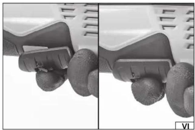
natural_image
Close-up of a mechanical component with textured surfaces, showing two views (top and side) with no visible text or symbols.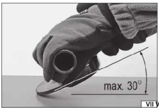
natural_image
Close-up of hands using a power tool to cut a circular component, with rotation arrows indicating clockwise motion (no text or symbols visible)- body
- additional handle
- abrasive disk guard
- spindle
- spindle lock
- switch
- speed regulation
- abrasive disk (grinding wheel)
- lower mounting fl ange
- upper mounting fl ange
- rechargeable battery
- battery charger
- battery charge indicator
- battery latch
DE
Read the operating instruction
Wear hearing protectors
Gehörschutz tragen
Wear protective goggles
Schutzbrille tragen
Do not use for cutting
Always work the grinder holding it with two hands
This symbol indicates that waste electrical and electronic equipment (including batteries and storage cells) cannot be disposed of with other types of waste. Waste equipment should be collected and handed over separately to a collection point for recycling and recovery, in order to reduce the amount of waste and the use of natural resources. Uncontrolled release of hazardous components contained in electrical and electronic equipment may pose a risk to human health and have adverse effects for the environment. The household plays an important role in contributing to reuse and recovery, including recycling of waste equipment. For more information about the appropriate recycling methods, contact your local authority or retailer.
The angular grinder is an electric tool designed for grinding and cutting metals as well as mineral construction materials, such as bricks, natural and artificial stone, concrete, glaze, etc. with abrasive disks and grinding wheels selected for the given material. The tool must not be used for processing other materials than those mentioned above, e.g. for grinding and cutting wood or polishing. A correct, reliable and safe functioning of the grinder depends on its proper use, so:
Before you proceed to operate the grinder, read the manual thoroughly and keep it.
Always use protective goggles!
Do not use grinding wheels whose maximum acceptable tangential velocity is lower than 80 m/s!
Do not use grinding wheels whose maximum acceptable rotational speed is lower than the rotational speed of the grinder.
The supplier will not be held responsible for any damage resulting from the safety regulations and the recommendations indicated hereby not being observed.
EQUIPMENT
The product is supplied in a complete state but it requires some installation activities before starting its operation. The product is supplied with the battery charger and charging station (charger). abrasive disk guard, the wrench for mounting the grinding wheel and the auxiliary handle. The equipment does not include grinding wheels.
Attention! The product of the catalog number: YT-82827 has not been equipped with a rechargeable battery and charging station.
TECHNICAL PARAMETERS
| Parameter Unit Value | |||
| Catalog number YT-82826, YT-82827 YT-82828 | |||
| Mains voltage [V] 18 DC 18 DC | |||
| Rated revs [min] | ^-1 PLN 10,000.00 PLN 10,000.00 | ||
| Diameter of the abrasive disk [mm] 125 125 | |||
| Diameter of the abrasive disk hole | [mm] | 22.2 22.2 | |
| Spindle tip | M14 M14 | ||
| Weight | [kg] | 1.5 | 1.5 |
| Noise level | |||
| - acoustic pressure LpA ± KpA | [dB (A)] | 88.0 ± 3.0 | 88.0 ± 3.0 |
| - power L_wA ± K | [dB (A)] | 99.0 ± 3.0 | 99.0 ± 3.0 |
| Vibration level _ah,AG ± K | [m/s2] | 4.9 ± 1.5 | 4.9 ± 1.5 |
| Insulation class | III | III | |
| Degree of protection | IPX0 | IPX0 | |
| Type of the battery | Li-Ion | Li-Ion | |
| Capacity of the battery* | [Ah] | 2 | 3 |
| Charger* | |||
| Input voltage | [V] | 220 - 240 | 220 - 240 |
| Mains frequency | [Hz] | 50 / 60 | 50 / 60 |
| Output voltage | [V] 21 DC 21 DC | ||
| Input current | [A] | 2.4 | 2.4 |
| Rated power | [W] | 60 | 60 |
| Time of charging** | [h] | 1 | 1,5 |
* only for models equipped with a battery and charger
** the specified charging time applies only to the battery with the capacity listed in the table.
The declared noise emission value has been measured using the standard test method and can be used to compare one tool to another. The declared noise emission value can be used in the preliminary exposure assessment.
The declared total vibration value has been measured using the standard test method and can be used to compare one tool to another. The declared total vibration value can be used in the initial exposure assessment.
Caution! The vibration emission during tool operation may differ from the declared value, depending on the manner the tool is used. Caution! Safety measures to protect the operator, which are based on an assessment of exposure under actual conditions of use (including all parts of the work cycle, such as the time when the tool is switched off or idle and the activation time), must be specified.
EN
GENERAL SAFETY CONDITIONS
NOTE! Get acquainted with all the instructions below. Failure to observe them may lead to an electric shock, fire or injuries. The notion of electric tool used in the instructions applies to all the tools which are powered with electric current, both wire tools and wireless ones.
OBSERVE THE FOLLOWING INSTRUCTIONS
Place of work
The place of work must be properly illuminated and clean. Disorder and poor illumination may be a cause of accidents.
Do not work with electric tools in explosive environments, or those which contain inflammable liquids, gases or vapours.
Electric tools generate sparks, which may cause a fire in case of contact with inflammable gases or vapours.
Do not allow children and outsiders to the place of work. A lack of concentration may result in a loss of control over the tool.
Electric safety
The plug of the power supply cable must fit the mains socket. Do not modify the plug. Do not use any adapters whatsoever in order to adapt the plug to the socket. Unmodified plug which fits the socket reduces the risk of an electric shock.
Avoid contact with grounded surfaces, such as pipes, heaters and refrigerators. Grounding of the body increases the risk of an electric shock.
Do not expose electric tools to precipitation or humidity. Water and humidity which gets into the electric tool increases the risk of an electric shock.
Do not overload the power supply cable. Do not use the power supply cable in order to carry the tool or to connect and disconnect the plug from the mains socket. Avoid contact of the power supply cable with heat, oils, sharp tools and moving elements. Damage to the power supply cable increases the risk of an electric shock.
In case work is realised outside closed areas, it is necessary to use extension cords designed for applications outside closed areas. Using a correct extension cord permits to reduce the risk of an electric shock.
If operating a power tool in a damp location is unavoidable, use a residual current device (RDC) protected supply. Use of an RCD reduces the risk of electric shock.
Personal safety
Commence work in good physical and psychological conditions. Pay attention to what you do. Do not work if you are tired or under effects of medicines or alcohol. Even a moment's inattention during work may lead to serious injuries.
Always use individual means of protection. Always wear goggles. Using individual means of protection, such as dust-masks, protective shoes, helmets and hearing protections permits to reduce the risk of serious injuries.
Avoid accidental activation of the tool. Make sure the switch is in the OFF position, before you connect the tool to the mains. Holding the tool with a finger on the switch or connecting an electric tool when the switch is in the ON position may lead to serious injuries.
Before you turn an electric tool on remove all the spanners and other tools, which have been used for adjustments. A spanner left on rotating elements of the tool may lead to serious injuries.
Keep your balance. Maintain an appropriate position. It will permit to control the electric tool in case of unpredicted situations during its operation.
Use protective clothes. Do not wear loose clothes or jewellery. Keep your hair, clothes and gloves away from moving elements of the electric tool. Loose clothes, jewellery or long hair may get caught on moving elements of the tool.
Use dust extractors or dust containers, if the tool is equipped with any. Make sure they are properly connected. Using of dust extractors permits to reduce the risk of serious injuries.
Safety precautions while using the electric tool
Before the battery is installed, make sure the switch is off. Installation of the battery when the switch is on may lead to accidents. Use solely the charger recommended by the manufacturer. Using a charger designed for another type of battery may be a cause of fi re.
The electric tool must be operated exclusively with the battery indicated by the manufacturer. Using another battery may be a cause of fire or injuries.
When the battery is not used, it must be stored away from such metal objects as paper clips, coins, nails, screws or other small metal elements, which might short-circuit the terminals. Short-circuited terminals of the battery may cause burns or fire.
Under adverse circumstances liquid may leak from the battery; avoid any contact. In case of accidental contact with the liquid, rinse it with water. In case of eye contact, seek medical. The liquid leaking from the battery may cause irritation or burns.
During work when the tool may touch a hidden live conductor, the electric tool must be held by insulated handles. The installed bit in case of contact with a live conductor may conduct electricity to the metal elements of the tool, which may cause electric shock to the operator.
EN
Repairs
The tool may be repaired only by authorised service centres, which must use solely original spare parts. It will guarantee a proper level of safety of operation of the electric tool.
ADDITIONAL SAFETY GUIDELINES FOR DISC GRINDERS AND POLISHING MACHINES
The tool is intended only for grinding, grinding with sandpaper, grinding with wire brushes and cutting. Read and view all warnings, instructions, figures, and specifications supplied with the power tool. Failure to follow all of the instructions provided below may result in electrocution, fire, or serious injury.
Do not convert this tool to make it fit for a job for which it has not been designed and specified by the manufacturer. Such conversion will result in loss of control and cause serious injuries.
It is prohibited to use the tool as a polishing machine or in any other manner which is non-compliant with the manual.
Performing other works for which the tool is not intended may pose a risk and result in injuries.
Do not use accessories that have not been designed or intended for the work with the tool by the manufacturer. The fact that the accessories can be installed on the tool does not ensure safe operation.
The maximum rotational speed of the accessories must be equal to or greater than the maximum rotational speed of the tool. Accessories with a lower rotational speed than the tool speed can disintegrate into fragments during operation.
The outer diameter and thickness of accessories must be within the size range specified for the tool. It is not possible to properly guard or operate improperly sized accessories.
The size of the hole used for fixing wheels, discs, flanges, and other accessories must match the size of the tool spindle. Accessories with a fixing hole size not suitable for the tool spindle size will start to vibrate during operation, which may result in the loss of control of the tool.
Do not use damaged accessories. Before each use, examine the condition of the accessories for possible splinters, cracks, abrasions and excessive wear. If any accessories are dropped, check them for damages or install new and undamaged accessories. After checking and installing the accessories, make sure you and all bystanders stand outside the rotation plane of the accessories, then run the tool for one minute at a maximum rotational speed. Damaged accessories will disintegrate during the test.
Wear personal protective equipment. Use face shields, goggles, or safety goggles, depending on the application. If required, use dust masks, hearing protection, safety gloves, and aprons to protect against small pieces of accessories or materials generated during work. The eye protection must allow for stopping any flying debris generated during work. The dust mask must be capable of filtering out dust generated during work. Exposure to noise for too long can result in hearing loss.
Ensure all bystanders keep a safe distance from the work area. Persons entering the work area must wear personal protective equipment. Debris or pieces of damaged accessories which are generated during work can be thrown out of the immediate vicinity of the work area.
When carrying out work during which the disc may come into contact with a live concealed electrical cable or power cord, hold the sander by the insulated handles only. When the disc is in contact with a live wire, it may cause the metal parts of the tool to become live, which may lead to electrocution of the tool operator.
Keep the power cord away from rotating tool parts. If you lose control of the tool, the cord can be cut or caught, and your hand or arm can be drawn into the rotating parts of the machine.
Never put down the tool until the rotating parts have come to a complete standstill. The rotating parts can “catch” the ground and pull the tool out of your control.
Do not turn on the tool while carrying it around. Inadvertent contact with rotating parts can cause your clothes to be caught and pulled in by the tool, which can result in contact with the operator's body.
Clean the tool's ventilation openings regularly. The motor fan draws dust generated during operation inside the tool. Excessive accumulation of metal particles contained in the dust increases the risk of electrocution.
Do not use the tool near flammable materials. Sparks generated during operation may cause a fire.
Do not use accessories that require liquid cooling. Water or coolant may lead to electrocution.
The thread size of the accessories must match the thread of the sander spindle. For flange-mounted accessories, the fixing hole for the accessories must match the size of the fixing flange. Accessories which do not fit into the power tool mount will cause imbalance, excessive vibration and may result in loss of control.
Warnings related to tool kickback towards the operator
The kickback of the tool towards the operator is a sudden reaction to a blocked or clamped: rotating disc, polishing belt, brush or other accessory. Blocking or jamming causes a rotating accessory to stop suddenly, which results in the power tool rotating in the opposite direction to the accessory rotation.
For example, if the grinding wheel is blocked or clamped by the workpiece, the edge of the disc that enters the clamping point may sink into the surface of the material causing the disc to come out or be ejected.
The disc can also be ejected towards or away from the operator, depending on the direction of the grinding wheel movement at the jamming point. Abrasive discs may also break in these conditions.
The tool kickback towards the operator is a result of misuse or failure to follow the guidelines in the manual. This phenomenon can
EN
be avoided by following the instructions below.
Use a firm grip on the tool and the correct body posture and hands position to withstand the forces generated by the kickback. Always use an additional handle, if supplied with the tool, to ensure maximum control during the kickback or any unexpected rotation during the tool start. The operator will be able to control the tool rotation or the kickback if appropriate precautions are taken.
Keep your hands away from rotating tool parts. The rotating parts can come into contact with your hands during kickback.
Do not stand in the area where the tool may move during the kickback. The kickback will direct the tool in the opposite direction to the direction of the abrasive disc rotation at the jamming point.
Pay special attention when working near corners, sharp edges, etc. Prevent the abrasive disc from runout and being jammed. When machining corners or edges, there is an increased risk of the grinding wheel jam, leading to a loss of control or tool kickback.
Do not use discs with a cutting chain for wood processing, segmented diamond discs with circumferential spacing between segments greater than 10 mm or discs with teeth. Such discs cause frequent kickbacks and loss of control of the tool.
Warnings related to grinding and cutting
Use only discs intended for work with a chosen tool and guards designed for a given type of disc. The discs for which the tool is not designed cannot be properly guarded and are not safe.
The convex disc must be mounted in such a way that the grinding surface does not protrude beyond the plane of the protective flange of the guard. An incorrectly mounted disc that protrudes above the guard poses a risk to safety during operation.
The guard must be securely attached to the tool and positioned for maximum safety so that the smallest possible area of the disc is exposed towards the operator. This guard helps to protect the operator from broken disc fragments and prevents accidental contact with the disc.
The disc must be used as intended. For example, do not grind with a cutting disc. Abrasive discs for cutting are designed for circumferential load, lateral forces applied to such a disc may cause it to disintegrate.
Always use undamaged fixing discs, which are of the correct size adapted to the abrasive disc. The correct fixing discs for the abrasive discs reduce the possibility of damage to the abrasive discs. The fixing discs for cutting discs can be different from the fixing discs for abrasive discs.
Do not use worn abrasive discs from larger tools. A larger diameter grinding wheel is not suited for a higher rotational speed of smaller tools and may break.
If you use dual-purpose discs, always use a guard appropriate for the type of work. The use of the wrong guard may lead to the failure to provide the desired degree of protection, which can lead to serious injury.
Warnings related to cutting
Do not “jam” the disc or apply too much pressure. Do not try to cut too deep. Excessive stress of the grinding wheel increases load and susceptibility for twisting or catching the disc in the cut groove, which increases the risk of kickback towards the operator or disc damage.
Do not place your body in the cutting line or behind the rotating grinding wheel. If during operation, the grinding wheel rotates in the direction away from the operator's body, the kickback towards the operator can direct the rotating disc and tool towards the operator.
If the disc is caught or the cut is interrupted for any reason, turn off the tool then keep it at a standstill until the disc rotation stops completely. Never attempt to get the rotating cutting disc out of the groove as it may result in kickback towards the operator. It is recommended to find causes and take appropriate steps to prevent the disc from being caught.
Do not resume cutting in the material. Allow the disc to achieve its nominal rotational speed and only then carefully insert it into the cut groove. The disc may be clamped, pulled out, or kicked back towards the operator if the cut is resumed in the material.
Support panels and other oversized materials to minimise the risk of clamping and kickback towards the operator. Oversized materials tend to bend under their own weight. The supports must be placed under the material close to the cutting line and close to the edge of the material on both sides of the cutting line.
Take special care when performing deep cuts in the walls or other unknown surfaces. A protruding disc may cut through gas pipes, electric cables, or other objects that may cause a kickback towards the operator.
Do not attempt to cut following the shape of an arc. Overloading the disc increases its load and susceptibility to twisting or jamming in the cut groove and the likelihood of kickback towards the operator or disc damage, which can lead to serious injury.
Warnings related to grinding with sandpaper
Use the correct size sandpaper. When selecting a grinding wheel, follow the manufacturer's recommendations.
Sandpaper that protrudes well beyond the disc may cause injury, and also increase the risk of jamming, tearing or kickback towards the operator.
EN
Warnings related to the work with the wire brush
Be careful, as wire fragments are also ejected from the brush during normal operation. Do not overload the wires by applying too much pressure to the brush. The wires can easily pierce thin clothing or skin.
If the use of guards is recommended during the work with the wire brush, prevent any contact of the brush with the guard. The wire brush can increase its diameter under load and centrifugal force.
Safety warnings related to polishing
Do not allow any loose part of the polishing disc or fastening cord to rotate freely. Loose and rotating cords can entangle in the fingers or be caught in the workpiece.
PREPARATION FOR WORK
ATTENTION! All the operations mentioned in this point must be realised with the power supply off.
- the battery must be disconnected from the tool!
Safety recommendations for battery loading
Attention! Before loading may start make sure the body of the charger, the cable and the plug are not broken or damaged. It is prohibited to use a damaged loading dock and charger! For the purpose of loading batteries only the charging dock and the charger provided may be used. Using another charger may be a cause of fire or damage the tool. Batteries may be charged only in a dry room, protected from unauthorised persons, particularly children. Do not use the charging dock and the charger without permanent supervision of an adult! If it is necessary to leave the room where loading is taking place, it is required to disconnect the charger from the mains, removing the charger from the mains socket. In case when smoke comes out of the charger, or a strange smell is emitted, etc., it is required to immediately remove the plug of the charger from the mains socket!
The tool and automatic return screwdriver is provided with an unloaded battery, so before work may commence, it is required to charge it following the procedure below, using the charger and charging dock provided. Li-ION batteries do not show the so called “memory effect”, so it is allowed to charge them at any moment. However, it is recommended to discharge them during normal work, and then load them to their full capacity. If due to the nature of the task it is not possible to do so each time, then it is required to do it at least from time to time. Under no circumstances is it allowed to discharge the batteries short-circuiting the electrodes, since this would cause irreversible damage! It is also prohibited to check the load of the batteries, short-circuiting the electrodes for sparking.
Storage of the battery
In order to prolong the life of the battery, it is required to provide adequate storage conditions. The batteries can go through approximately 500 „loading - discharging” cycles. The battery must be stored between 0 and 30°C, at the relative humidity of 50%. In order to store the battery for a prolonged period, it is required to charge it to approximately 70% of its capacity. In case of prolonged storage, it is required to recharge the battery once a year. Do not permit excessive discharging of the battery, since this would reduce its life and may cause irreversible damage.
During storage, the battery will be gradually unloading due to leakage conductance. The process of automatic unloading depends on the temperature of storage, since the higher the temperature, the fastest the process. In case of incorrect storage of batteries, there is a danger of electrolyte leakage. In case of leakage, it is required to protect the leakage with neutralizing agent. In case of contact of electrolyte with the eyes, it is required to rinse the eyes abundantly, and then immediately seek medical assistance. It is prohibited to use a tool with a damaged battery.
In case the battery is completely worn out, it is required to deposit it at a special point dedicated to disposal of such waste.
Transport of the batteries
Lithium-ion batteries are in accordance with legal regulations treated as dangerous waste. The user of the tool may transport the tool with the battery or only batteries by land. Then no additional conditions must be complied with. In transport is realised by third parties (for example dispatch through courier service), then it is required to proceed in accordance with regulations for transport of dangerous materials. Before shipment, contact an authorised person.
It is prohibited to transport damaged batteries. During transport the battery must be removed from the tool, and the exposed contacts protected, e.g. with insulating tape. Protect the batteries so that they do not move inside the package during transport. It is also required comply with the national regulations for transport of dangerous materials.
Charging the battery
Attention! Before charging you should disconnect the charger from the mains by unplugging the power supply plug from the mains. In addition, you should clean the battery and its terminals of dirt and dust with a soft, dry cloth.
The battery has a built-in charge indicator. When you press the button, LEDs will light up (II), the more LEDs will light up, the more fully the battery pack is charged. If the button is pressed and the LEDs are off it means that the battery is discharged.
Disconnect the battery from the tool.
Push the battery in the charger socket (II).
Plug the charger into a mains socket.
EN
When the red LED lights up, it means the loading process.
When charging is complete, the red LED goes off, and green LED lights up, indicating a full charge of the battery.
Unplug the charger from the mains outlet.
Remove the battery from the charging station, by pressing the battery latch button.
Attention! If, when the charger is connected to the power supply, the green LED is on, this indicates a fully charged battery. In this case, the charger does not start charging.
ASSEMBLY OF EQUIPMENT ELEMENTS
Assembly of the abrasive wheel guard
For this purpose, you should put on the wheel cover on the cylindrical body part around the spindle and with a screw or clip of cover ring clamp, immobilize it, so the cover will be mounted straight ahead, firmly and tightly. Set the guard of the grinding wheel, so the unsheltered part of the grinding wheel will be as far as possible from the hand of a grinder user. Never work with the grinder without correctly mounted grinding wheel guard!
With the grinder there is supplied the guard, which provides the adequate protection only when grinding with abrasive wheels and wheels using sandpaper and some wire brushes. After installing the wheel on the spindle, the accessory must not protrude beyond the side guard. In the case of performance of any other type of allowed work, you should contact the manufacturer to acquire the guard intended for this kind of work.
Installation of auxiliary handle
Mount the handle by its firm screwing to the tool heading. The handle has a socket, which allows to store the wrench for fixing the grinding wheel. This makes it easier to store the wrench. After completion of all works requiring to use the wrench it should be inserted in the socket and you should make sure that it does not slip spontaneously by its own weight.
OPERATION OF THE GRINDING WHEELS
ATTENTION! Mounting of the abrasive wheels may be done only with disconnected power supply. Remove the battery pack from the power tool socket!
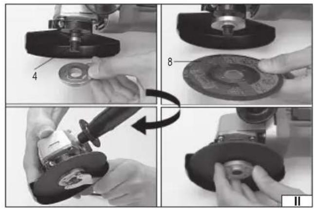
Installing the wheels
Disconnect power supply voltage from the tool. Remove the battery pack from the power tool socket!
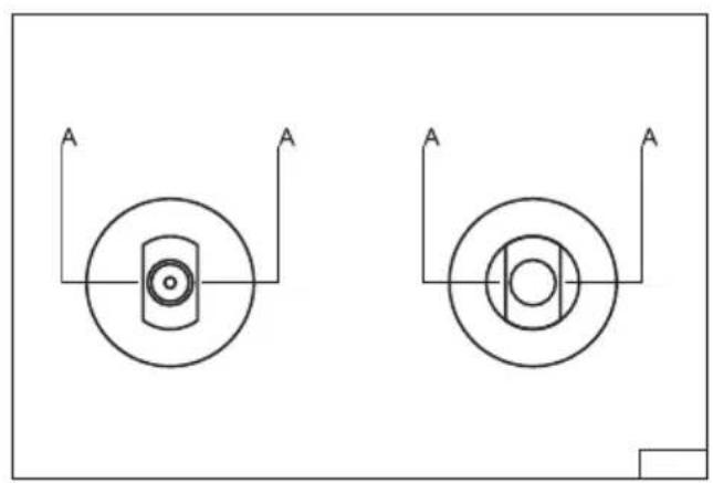
During the assembly please pay attention, that the edges A (IV) at the bottom of the spindle shaft and of the mounting flanges exactly overlap.
Install the top mounting fl ange on spindle,
Mount the grinding wheel on the spindle and on the upper mounting flange.
Screw the bottom mounting fl ange on the spindle.
Press the spindle lock and tighten the lower mounting flange with a key and then release the lock button.
Mount the battery to the power tool, turn on the grinder and watch its work without any load by the time of about 1 minute.
Remove the battery and inspect the wheels mounting.
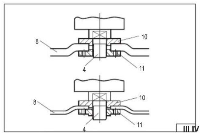
The location of the mounting fl anges
Please pay attention, that grinding wheels, in the point of mounting to the spindle, can vary in their thickness.
Depending on the applied grinding wheels, which are thin (thickness up to 3.2 mm), or thick (thickness above 3.2 mm) the positioning of mounting flanges (III) is different. Do not use wheels thicker than 6 mm.
Removing the grinding wheels
Turn off the grinder and remove the battery.
Press the spindle lock and loosen the lower mounting flange with the wrench for mounting, and then remove the abrasive wheel from the spindle. Clean the spindle and clamping flanges of dust and other pollutants arising in the course of work.
Types of abrasive wheels
You can use for grinder all grinding wheels designed for use with angle grinders with a permissible peripheral speed of at least 80 m/s and fixing and external diameters specified in the technical data table.
If the grinding wheel is equipped with an unthreaded hole, for its mounting you should use the mounting flanges.
It is also possible to mount the grinding wheels with an outside diameter specified in the technical data table, equipped with a threaded hole M14. In this case, you should not use the mounting flanges, and the grinding wheel should be screwed directly to the spindle, by blocking it with a button, and by tightening the blade firmly and securely with a flat wrench (the grinder is not equipped with it).
In the case of wheels, which allow for mounting the sandpaper wheel by using Velcro, you should only use the sandpaper wheels, which are specified in the table of technical data. The wheels should be placed concentrically on the grinding wheel. The edge of
EN
the wheel should not protrude beyond the wheel edge.
It is also possible to use diamond grinding wheels with dimensions specified in the technical data table, intended for cutting and dry grinding. Installation should be carried out in the same way as for grinding wheels.
For metal treatment it is recommended to use grinding wheels made of materials intended for the processing of a given type of metal. Refer to the documentation that is attached to the grinding wheel.
For the processing of ceramic materials you can use the grinding wheel or diamond grinding wheels, designed for a dry work.
Wire brushes and sanding wheels are recommend for removing old paint coatings from metal parts.
It is prohibited to modify the mounting hole, spindle or use reduction rings in order to align the mounting hole diameter to the diameter of spindle. It is prohibited to use grinding wheels with a mounting diameter other than the diameter specified in the technical data table. It is forbidden to use wheels with the cutting chain or disk saws. because that increases the risk of tool rebound toward the operator.
Attention! It is forbidden to use other grinding wheels than those, which are approved for use in this manual. Even if they can be mounted on the grinder spindle. Inappropriate grinding wheels may not withstand the loads generated during the operation of the angle grinder. Damaged, crumbling grinding wheels create a threat of serious injury or death.
USE OF THE GRINDER
Remove the battery from the power tool socket!
Before working with the tool, you should check whether the enclosure, cover and battery are not damaged.
If there are any visible damages it is prohibited to operate the grinder!
Attach the cover of grinding wheel and the handle.
Never work with the grinder without correctly mounted grinding wheel guard!
Choose the type of grinding wheel, which is appropriate for the type of work, and mount the grinding wheel on the grinder spindle.
Workpiece should be mounted in an appropriate way, so it does not move during its machining, for example, by clamps or clips.
The wheel of grinder spins at high speed and improper mounting of the workpiece can cause its uncontrolled movement during operation, which increases the risk of injury.
In the case of cutting you should support the cut material on both sides of the cut line, but in such a way, that during cutting it would not cause the grinding wheel jam. Supports should be positioned near the edges of cut material, and near the cut line.
Wear eye protection, hearing protectors and working gloves.
Check, whether the switch is in the "off - 0" position. Then connect the battery to the power tool.
Adopt the proper body position, which is needed to maintain balance, and run the grinder by its switch.
The switch has a security lock to prevent accidental starting of the grinder. Move the lock back so it will be at level of the switch surface, and then will allow to press it. The switch does not have the possibility of blocking in the ON position, you should hold it all the time during the work.
Proceed to work by applying the proper surface of the grinding wheel to workpiece:
- in the case of grinding wheels for grinding you should grind by the side and/or front surface,
- in the case of flap grinding wheels you should grind by the surface side so that the sandpaper leaves would move parallel to the workpiece,
- in the case of wheels with Velcro, which allow for fixing the abrasive paper, grinding must be carried out by side surface,
- in the case of wire brushes the treatment should be done by wires endings, not by their side surface,
- in the case of grinding wheels for cutting, you should cut by their front surface, do not grind by the front surface of grinding wheels, which are designed for cutting.
When grinding with a side surface you should keep the grinder at an angle of no more than 30 degrees with respect to the treated surface (VII). Move the grinder forward and back by smooth moves.
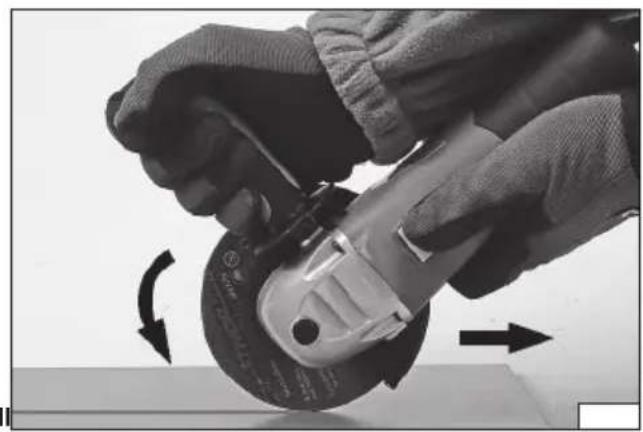
During cutting, the grinding wheel should be at a right angle relative to the cut surface. Do not make the cut at a different angle. It is forbidden to change an angle of the cutting grinding wheel in relation to the workpiece during the cutting operation. The cut should be made only in a straight line. Failure to follow these guidelines increases the risk of grinding wheel jam in workpiece, which can cause rebound of tool toward the operator, rupture of the grinding wheel or its disintegration
uring cutting, drive the grinder in the direction of rotation of the wheel (VIII).
During grinder operation, do not exert too much pressure on the treated material, and do not make sudden movements, to not cause jamming, or cracks and bursts of grinding wheel.
Do not allow to overload the grinder, its external surfaces temperature should never exceed 60°C.
The grinder is stopped after releasing the pressure on the switch.
At the end of work you should turn off the grinder, remove the battery and make an examination.
Attention! The grinding wheel can rotate even for some time after the machine is switched off. You should wait until a complete stop of grinding wheel movement before putting away the grinder. Prior to the inspection you should wait for cooling of the grinding wheel. During the work, both, grinding wheel and workpiece material, can warm up to a high temperature.
EN
Remember! When operating the angle grinder:
Always use eye protection.
Do not use grinding wheels of a maximum allowable peripheral speed of less than 80 m/s.
Do not use grinding wheels of a maximum allowable rotational speed less than the rotational speed of the grinder.
MAINTENANCE AND OVERHAUL
ATTENTION! Before any adjustment, technical service or maintenance operations unplug the tool. Once the operations have been finished, the technical conditions of the tool must be assessed by means of external evaluation and inspection of the following elements: body and handle, conductor with a plug and deflection, functioning of the electric switch, patency of ventilation slots, sparking of brushes, noise level of functioning of bearings and gears, start-up and smoothness of operation. During the guarantee period, the user cannot dismantle the electric tools or change any sub-assemblies or elements, since it will cancel any guarantee rights. All irregularities detected at overhaul or during functioning of the tools are a signal to have the tool repaired at a service shop. Once the functioning has been concluded, the casing, ventilation slots, switches, additional handle and protections must be cleansed with a stream of air (at a pressure not exceeding 0.3 MPa), with a brush or a cloth without any chemical substances or cleaning liquids. Tools and handles must be cleansed with a clean cloth.
CHARAKTERISTIK DES WERKZEUGES
EN IEC 62841-2-3:2021 + A11:2021
EN IEC 55014-1:2021
EN IEC 55014-2:2021
DECLARATION OF CONFORMITY
0125/YT-82826/EC/2025
We declare and guarantee with full responsibility that the following products:
Cordless angle grinder 18 V d.c.; 10000 min ^-1 ; 125 mm; item no. YT-82826, YT-82827, YT-82828
meet requirements of the following European Standards / Technical Specifications:
EN 62841-1:2015 + A11:2022
EN IEC 62841-2-3:2021 + A11:2021
EN IEC 55014-1:2021
EN IEC 55014-2:2021
and fulfill requirements of the following European Directives:
2006/42/EC Machinery and safety elements
2014/30/EU Electromagnetic compatibility (EMC) Directive
2011/65/EU Restriction of the Use of Certain Hazardous Substances
Serial number: concern all serials numbers of item(s) mentioned in this declaration
The person authorized to compile the technical file:
Agnieszka Rędziak
(Place and date of issue)
V-CE PREZES ZARZADU
JAN SZMIDT
(Name and signature of authorized person)
TOYA S.A.
EN IEC 62841-2-3:2021 + A11:2021
EN IEC 55014-1:2021
EN IEC 55014-2:2021


- DE
- EQUIPMENT
- EN
- GENERAL SAFETY CONDITIONS
- OBSERVE THE FOLLOWING INSTRUCTIONS
- Place of work
- Electric safety
- Personal safety
- Safety precautions while using the electric tool
- Repairs
- ADDITIONAL SAFETY GUIDELINES FOR DISC GRINDERS AND POLISHING MACHINES
- Warnings related to tool kickback towards the operator
- Warnings related to grinding and cutting
- Warnings related to cutting
- Warnings related to grinding with sandpaper
- Warnings related to the work with the wire brush
- Safety warnings related to polishing
- PREPARATION FOR WORK
- Safety recommendations for battery loading
- Storage of the battery
- Transport of the batteries
- Charging the battery
- ASSEMBLY OF EQUIPMENT ELEMENTS
- Assembly of the abrasive wheel guard
- Installation of auxiliary handle
- OPERATION OF THE GRINDING WHEELS
- Installing the wheels
- The location of the mounting fl anges
- Types of abrasive wheels
- USE OF THE GRINDER
- Remember! When operating the angle grinder:
- MAINTENANCE AND OVERHAUL
- CHARAKTERISTIK DES WERKZEUGES
- DECLARATION OF CONFORMITY
Brand : Yato
Model : YT82827
Category : Grinder