YT-82350 - Grinder Yato - Free user manual and instructions
Find the device manual for free YT-82350 Yato in PDF.

| Product Type | Wall sander with arm (grinder) |
| Brand | Yato |
| Model | YT-82350 |
| Mains Voltage | 230-240 V, 50 Hz |
| Rated Power | 710 W |
| Rated Speed (disc) | 600-1500 min⁻¹ |
| Rated Oscillations (delta head) | 3000-6000 min⁻¹ |
| Spindle Diameter | M6 |
| Disc Support Diameter | 215 mm |
| Sanding Disc Diameters | 225 / 215 / 210 mm |
| Weight | 3.39 kg |
| Sound Level (Sound Pressure) | 88 dB(A) ±3 |
| Sound Level (Sound Power) | 99 dB(A) ±3 |
| Vibration Level (disc) | 3.48 m/s² ±1.5 |
| Vibration Level (delta head) | 3.51 m/s² ±1.5 |
| Insulation Class | II (double insulation) |
| Protection Degree | IP20 |
| Main Functions | Wall and large surface sanding, dust extraction, foldable arm and extension, head change (disc or delta) |
| Included Equipment | Abrasive paper sheets, flexible hose, additional delta head, extension |
| Maintenance and Cleaning | Clean with a dry cloth, compressed air (max 0.3 MPa) or soft brush; do not use chemicals or liquids |
| Safety | Mandatory use of hearing protection, gloves, goggles and dust mask; switch with lock; kickback prevention |
| Spare Parts and Repairability | Repairs exclusively at an authorized service center; use of original parts; warranty void if unauthorized disassembly |
| General Information | Use only for sanding with abrasive paper; mandatory reading and keeping of the manual |
Frequently Asked Questions - YT-82350 Yato
User questions about YT-82350 Yato
0 question about this device. Answer the ones you know or ask your own.
Ask a new question about this device
Download the instructions for your Grinder in PDF format for free! Find your manual YT-82350 - Yato and take your electronic device back in hand. On this page are published all the documents necessary for the use of your device. YT-82350 by Yato.
USER MANUAL YT-82350 Yato
natural_image
Three-panel image showing a hand operating a mechanical device with a tool, no visible text or symbols.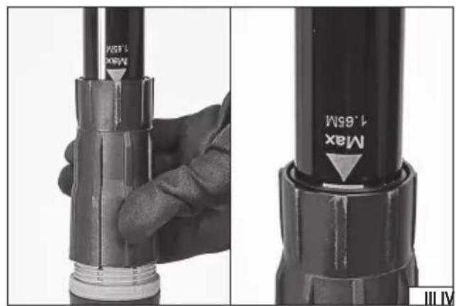
natural_image
Close-up of hands using a handheld electric shock absorber with coiled spring (no text or symbols visible)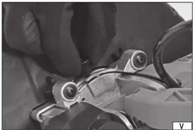
natural_image
Close-up of hands adjusting a mechanical component with visible gears and wires (no text or symbols)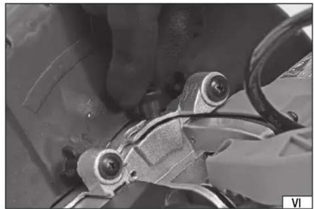
natural_image
Close-up of a hand adjusting mechanical components with visible screws and brackets (no text or symbols)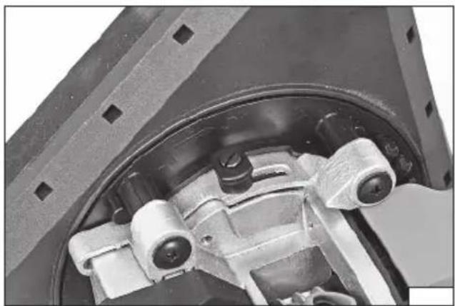
natural_image
Close-up of mechanical components including a brake caliper and housing (no visible text or symbols)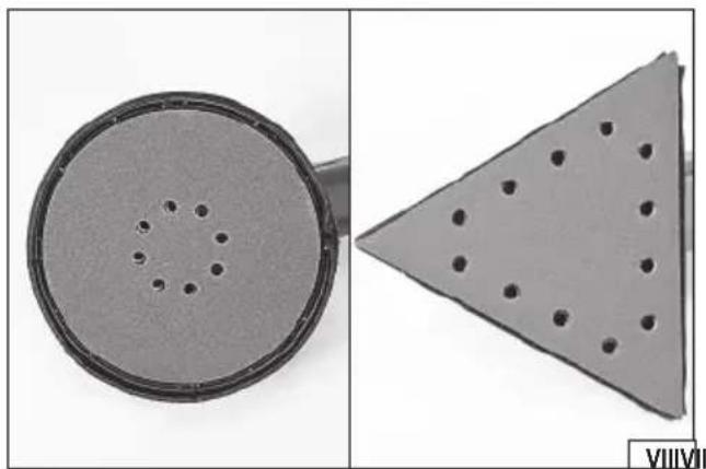
natural_image
Two views of a circular mechanical component with evenly spaced holes, shown from different angles (no text or symbols)natural_image
Close-up of a hand holding a white handheld device with a button, no visible text or symbols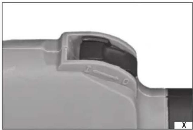
natural_image
Close-up of a mechanical component with labeled parts (T, C) and a small symbol 'X' in the corner (no readable text or symbols beyond labels)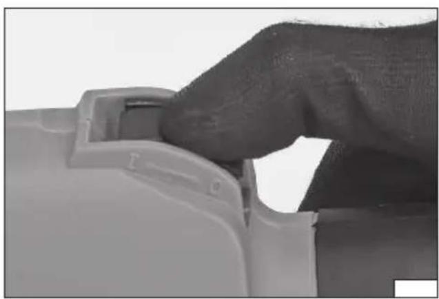
natural_image
Close-up of a hand pressing a button on a mechanical component (no visible text or symbols)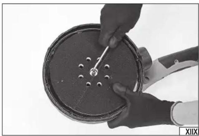
natural_image
Close-up of hands holding a circular mechanical component with a tool, no visible text or symbolsPL EN DE
Mains voltage and frequency
Rated oscillations (delta)
Sanding disc diameter
Direction of disc rotation
Read the operating instruction
Wear hearing protectors
Wear protective goggles
Schutzbrille tragen
This symbol indicates that waste electrical and electronic equipment (including batteries and storage cells) cannot be disposed of with other types of waste. Waste equipment should be collected and handed over separately to a collection point for recycling and recovery, in order to reduce the amount of waste and the use of natural resources. Uncontrolled release of hazardous components contained in electrical and electronic equipment may pose a risk to human health and have adverse effects for the environment. The household plays an important role in contributing to reuse and recovery, including recycling of waste equipment. For more information about the appropriate recycling methods, contact your local authority or retailer.
WYPOSAŻENIE PRODUKTU
The wall sander with a handle is a power tool using sanding discs to sand large, flat surfaces. Thanks to the long handle, it is possible to sand walls without using any platforms. The sander features a system for the extraction of dust generated during works, and a hose to connect the unit to a vacuum device, which reduces the amount of dust in the work area. As the proper use of the power tool is a condition for the correct, reliable and safe operation of it, please
read and preserve the entire Manual before the first use of the tool.
The Supplier shall not be held liable for any damage resulting from failure to observe the safety regulations and recommendations specified in this Manual.
ACCESSORIES
The unit is supplied as a complete package, but it requires some assembly work. The sander package includes
- sanding sheet
- hose
- additional sanding head
- extension arm
TECHNICAL PARAMETERS
| Parameter Measure Unit Value | ||
| Order No. YT-82350 | ||
| Power supply voltage [V] 230 - 240 | ||
| Power frequency [Hz] 50 | ||
| Rated power [W] 710 | ||
| Rated speed (disc) [min] | ^-1 600 - 1500 | |
| Rated oscillations (delta) [min] | ^-1 ] | 3000 - 6000 |
| Spindle size | M6 | |
| Disc fixing ring diameter | [mm] | 215 |
| Sanding disc diameter | [mm] 225 / 215 / 210 | |
| Weight | [kg] | 3.39 |
| Noise level | ||
| - sound pressure L_pA ± K_pA | [dB (A)] | 88.0 ± 3.0 |
| - power L_wA ± K_wA | [dB (A)] | 99.0 ± 3.0 |
| Vibration level _a1,AG ± K (disc/delta) | [m/s ^2 ] | 3.48 ± 1.5 / 3.51 ± 1.5 |
| Protection class | II | |
| Ingress Protection Rating | IP20 |
GENERAL WARNINGS FOR THE SAFETY OF POWER TOOLS
Warning! Read all safety warnings, illustrations and specifications provided with this power tool. Failure to do so may result in electric shock, fi re or serious injury.
Keep all warnings and instructions for future reference.
The term “power tool” used in warnings applies to all tools driven by power both wired and wireless.
Workplace safety
Keep the workplace well-lit and clean. Disorder and poor lighting can be causes of accidents.
Do not work with power tools in an environment with an increased risk of explosion, containing flammable liquids, gases or vapors. Power tools generate sparks that can ignite dust or fumes.
Children and third persons should not be allowed to enter the workplace. Loss of concentration can result in loss of control.
Electrical safety
The plug of the electric cable must match the power socket. You must not modify the plug in any way. Do not use any plug adapters with earthed power tools. An unmodified plug that fits the outlet reduces the risk of electric shock.
Avoid contact with earthed surfaces such as pipes, radiators and coolers. Grounding the body increases the risk of electric shock.
Do not expose power tools to contact with atmospheric precipitation or moisture. Water and moisture that gets inside the power tool increases the risk of electric shock.
EN
Do not overload the power cable. Do not use the power cord to carry, pull or unplug the power plug from the power outlet. Avoid contact of the power cable with heat, oils, sharp edges and moving parts. Damage or entanglement of the power cord increases the risk of electric shock.
In the case of working outside closed rooms, use extension cords intended for work outside closed rooms. The use of an extension cord adapted for outdoor use reduces the risk of electric shock.
When using a power tool in a humid environment is unavoidable as a protection against supply voltage use a residual current device (RCD). The use of RCD reduces the risk of electric shock.
Personal safety
Stay alert, pay attention to what you do and keep common sense while working with the power tool. Do not use a power tool when you are tired or under the influence of alcohol or medication. Even a moment of inattention while working can lead to serious personal injury.
Use personal protective equipment. Always wear eye protection. The use of personal protective equipment such as dust masks, anti-slip safety shoes, helmets and hearing protection reduce the risk of serious personal injury.
Prevent accidental operation. Make sure that the electric switch is in the “off” position before connecting to the power supply and / or battery, lifting or moving the power tool. Moving the power tool with the finger on the switch or powering the power tool, when the switch is in the “on” position can lead to serious injuries.
Before turning on the power tool remove any keys and other tools that were used to adjust it. The key left on the rotating parts of the power tool can lead to serious injuries.
Do not reach and do not lean too far. Keep the right attitude and balance all the time. This will allow easier control over the power tool in case of unexpected work situations.
Dress accordingly. Do not wear loose clothing or jewelry. Keep your hair and clothing away from moving parts of the power tool. Loose clothing, jewelry or long hair can be caught by moving parts.
If the devices are fitted for the connection of dust extraction or dust collection, make sure that they are connected and used properly. The use of dust extraction reduces the risk of dust hazards.
Do not let the experience acquired from frequent use of the tool resulted in carelessness and ignoring safety rules.
Carefree action can cause serious injuries in a fraction of a second.
Use and care of the power tool
Do not overload the power tool. Use the power tool appropriate for the selected application. The right power tool will provide a better and safer job if used according to the designed load.
Do not use the power tool, if the electric switch does not allow switching on and off. Power tool, which cannot be controlled by means of a power switch is dangerous and must be returned for repair.
Disconnect the plug from the power socket and / or remove the battery if it is detachable from the power tool before adjusting, changing accessories or storing the tool. Such preventive measures will allow you to avoid accidentally turning on the power tool.
Keep the tool out of the reach of children, do not let people who do not know how to operate the power tool or these instructions use a power tool. Power tools are dangerous in the hands of untrained users.
Maintain power tools and accessories. Check the tool for mismatches or jams of moving parts, damage to parts and any other conditions that may affect the operation of the power tool. Damage must be repaired before using the power tool. Many accidents are caused by incorrectly maintained tools.
Keep cutting tools sharp and clean. Properly maintained cutting tools with sharp edges are less prone to jamming and are easier to control when working.
Use power tools, accessories and inserted tools etc. in accordance with these instructions, taking into account the type and conditions of work. The use of tools for work other than designed is likely to result in a dangerous situation.
Handles and gripping surfaces must be dry, clean and free from oil and grease. Slippery handles and gripping surfaces do not allow for safe operation and control of the tool in dangerous situations.
Repairs
Repair the power tool only in authorized facilities using only original spare parts. This ensures proper operation safety of the power tool.
ADDITIONAL SAFETY INSTRUCTIONS
The tool is designed for sanding with sanding sheets only. Read and view all warnings, instructions, figures and specifications supplied with the power tool. Failure to follow all of the instructions provided below may result in electric shock, fire and/or serious injury.
It is prohibited to use the tool as a disc grinder, wire brush grinder, cutter, polisher or in any other way which is not compliant with the Manual. Operating a tool in a way which it has not been designed for can cause risks and lead to injuries.
Do not use accessories which have not been designed by the manufacturer or intended for the work with the sander. A possibility of mounting accessories on the tool does not ensure safe operation.
The maximum rpm of the accessories must be equal to or greater than the maximum rpm of the tool. Accessories with a
EN
lower rotational speed than the tool speed can disintegrate during operation.
The outer diameter and thickness of accessories must be within the size range specified for the tool. It is not possible to properly guard or operate improperly sized accessories.
The size of the hole used for fixing wheels, discs, flanges and other accessories must match the size of the tool spindle. Accessories with a fixing hole size not suitable for the tool spindle size will start to vibrate during operation, which may result in the loss of control of the tool.
Do not use damaged accessories. Before each use, examine the condition of the accessories for possible splinters, cracks, abrasions and excessive wear. If any accessories are dropped, make sure they are not damaged, or mount new, undamaged accessories. After you have checked and installed the accessories, make sure you and all bystanders stand outside the rotation plane of the accessories, then run the tool for one minute at maximum speed. Damaged accessories will disintegrate during the test.
Wear personal protective equipment. Use face shields, goggles or safety goggles, depending on the application. If required, use dust masks, hearing protection, safety gloves and aprons to protect against small pieces of accessories or materials generated during work. The eye protection must be capable of stopping any flying debris generated during work. The dust mask must be capable of filtering out dust generated during work. Exposure to noise for too long can result in hearing loss.
When carrying out work in which the disc may come into contact with a live, concealed electrical wire or power cord, grip the sander's insulated handles only. When in contact with a live wire, the disc can result in metal parts of the tool becoming live, which can lead to the tool operator suffering electric shock.
Ensure all bystanders keep a safe distance from the work area. Persons entering the work area must wear personal protective equipment. Debris or pieces of damaged accessories which are generated during work can be thrown out of the immediate vicinity of the work area.
Keep the power cord away from rotating tool parts. If you lose control of the tool, the cord can be cut or caught, and your hand or arm can be drawn into the rotating parts of the machine.
Never put down the tool until the rotating parts have come to a complete standstill. The rotating parts can "catch" the floor and pull the tool out of your control.
Do not run the tool while carrying it around. Inadvertent contact with rotating parts can cause your clothes to catch and be pulled in by the tool, which can come into contact with your body.
Clean the tool's ventilation openings regularly. The motor fan draws dust generated during operation inside the tool. Excessive accumulation of metal particles contained in the dust increases the risk of electric shock.
Do not use the tool near flammable materials. Sparks generated during operation may cause fire.
Do not use accessories which require liquid cooling. Water or coolant may cause electric shock.
Dust from sanding surfaces can be toxic. Avoid inhaling it, use respiratory protection and dust extraction system.
Caution! Tool kickback towards the operator
The kickback of the tool towards the operator is caused by a rotating disc, brush, polishing tape or other accessories, when suddenly blocked or clamped. Blocking or clamping causes a rotating accessory to stop suddenly, which results in the power tool rotating in the opposite direction to the accessory rotation.
For example, if the sanding disc is blocked or clamped by the workpiece, the edge of the disc which reaches the clamping point can sink in the surface of the material, causing the disc to escape or be ejected.
The disc can also escape towards or away from the operator, depending on the direction of the wheel movement at the clamping point. Sanding discs may also break in these conditions.
The tool kickback towards the operator is a result of misuse and/or failure to follow the guidelines in the User Manual. This occurrence can be avoided by following the instructions below.
Use a firm grip on the tool and the correct position of the body and hands to withstand the forces generated by the kickback. Always use an additional handle, if supplied with the tool, to ensure maximum control during the kickback or any unexpected rotation during the tool start. The operator will be able to control the tool rotation or the kickback if appropriate precautions are taken.
Keep your hands away from rotating tool parts. The rotating parts can come into contact with your hands, when kicked back.
Do not stand in the area where the tool may kick back. The kickback will direct the tool in the opposite direction to the direction of the sanding disc rotation, at the clamping point.
Pay special attention when working near corners, sharp edges, etc. Prevent the sanding disc from axial displacement and being jammed. When working corners or edges, there is an increased risk of the sanding disc jam, leading to a loss of control or tool kickback.
Do not use cutting chain discs or circular saws. The blades cause frequent kickbacks and the loss of control of the tool.
Caution! Sanding with sanding sheets
Do not use oversized sanding discs. When selecting a wheel, follow the manufacturer's recommendations. A sanding sheet which protrudes well beyond the disc may cause injury, and also increase the risk of jamming, tearing or kickback towards the operator.
EN
PREPARING THE MACHINE FOR OPERATION
Note! When assembling the components, pull out the power plug to disconnect the tool from the power supply.
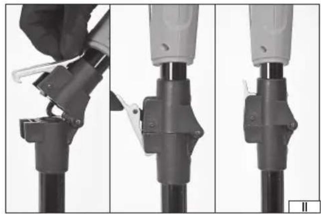
Sander Handle Assembly (II)
The sander feature a foldable handle, which saves space during storage and facilitates transport.
Before starting work, connect both parts of the handle in such a way that they do not come apart spontaneously during work. A snap coupling is used to connect the two parts. Lift the coupling, connect the two parts of the handle so that their surfaces are in full contact with each other. Then hook the coupling on the recess in the hinge and press it down so that both coupling parts can be fully closed.
The handle snap coupling is fitted with a gasket which prevents dust from escaping when it is transported inside the handle. Check the condition of the gasket before each handle coupling.
To disassemble the handle, follow the above procedure in the reverse order.
Sander Handle Extension Arm (III)
The sander comes with an extension arm. The extension arm is mounted at the end of the handle.
Before the assembly, loosen the nut at the end of the handle, but not fully. Move it a few turns counterclockwise.
Insert the extension arm so that it is inside the handle, and then move the extension arm fastener so that it rests on the edge of the handle nut. While pressing the fastener, tighten the nut clockwise to ensure the position of the extension arm will not be changed.
There is a mark on the extension arm which indicates the length to which it can be extended. Do not exceed the allowable extension arm length. If you do, this can cause the extension arm to slip out of the sander handle spontaneously, which can cause damage to the product and also lead to injury.
To disassemble the extension arm, follow the above procedure in the reverse order.
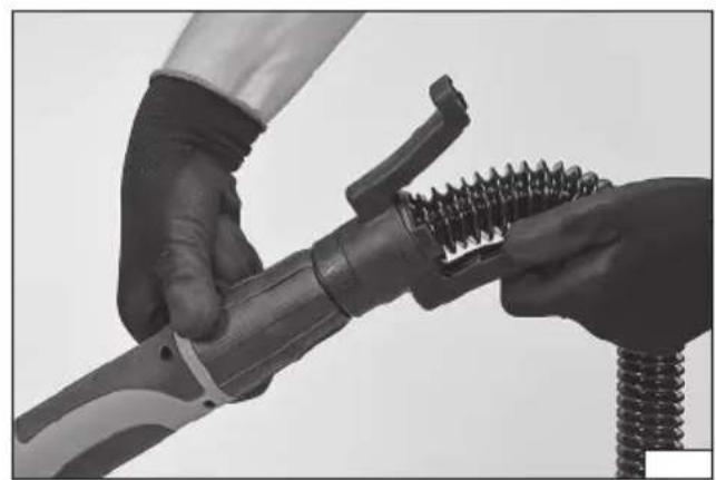
Dust Extraction Hose Assembly (IV)
The sander comes with a flexible hose which allows the sander to be connected to a dust extraction system such as an industrial vacuum cleaner.
Connect the hose to the end of the handle or to the end of the extension arm.
Before the assembly, loosen the nut at the end of the handle or the extension arm, but not fully. Move it a few turns counterclockwise.
Insert the hose end into the nut so that it rests on the hose edge. Pressing the hose end, tighten the clockwise. Check that the hose end does not slip out of the nut.
Connect the free end of the hose to the dust extraction system. This may require additional adapters which are not supplied with the product.
To disassemble the hose, follow the above procedure in the reverse order.
Changing the Sanding Head
The sander has a pre-assembled head with a rotating disc. The head is designed for sanding large areas. The sander also features a triangular work head (the delta) for sanding in corners. The head sanding action is in the form of oscillations.
The head is snapped in place and you do not require any additional tools to replace it.
Pull and hold the head snap coupling (V), then move it in the direction of the open padlock sign (VI). Dismount the work head from the drive housing.
Clean the mounting place of any dust and other contaminants with a soft, dry cloth.
Fit the head in the drive housing so that all the retaining pins go through the holes. Both the distribution of the pins and the shape of the mounting allows for only one correct mounting position. The edges of the head and drive housing must be parallel. Move the snap coupling towards the locked padlock sign and make sure it retracts into the housing recess (VII). Only this position of the coupling prevents the work head from being disconnected during operation.
Ensure the assembly has been correct. If the head cannot be detached from the drive housing, and if the locks of the head and drive housing are parallel, it means they are assembled correctly. Otherwise, the work head must be reassembled according to the procedure.
Sanding Sheet Replacement (VIII)
Note! Make sure the sanding sheet is free from damage before installing it. If you notice any damage in the form of folds, cracks, tears or holes, replace the sheet with a new one which is free of damage.
The sanding sheet must be provided with a surface which allows it to be attached on the disc by means of Velcro pad. The sheets should have holes in the same places as the holes in the tool disc. Only then will it be possible to extract the dust generated during operation effectively.
For the Disc Head, place the sheet on the disc coaxially so that the holes in the sheet match the holes in the tool disc. The edge of the sanding disc must not come into contact with the tool guard or the peripheral brush of the guard.
EN
For the Delta Head, place the sheet on the head so that the edges of the head are parallel to the edge of the sheet, and the holes in the sheet match the holes in the tool head.
PRODUCT OPERATION
Note! All the assembly steps described above must be carried out before you start working.
Starting the Sander
Do not start the sander while leaning the work head against any surface with the sanding sheet being in contact with any object.
This may lead to a loss of control of the tool and cause serious injury.
The sander is fitted with a rotary knob (IX), which allows you to adjust the motor speed, which translates into disk speed or the delta oscillation speed, depending on a head mounted. The knob is marked with appropriate signs to indicate the direction of the knob rotation for speed control.
Check that the product switch is in the "O" off position (X).
Move the speed controller to the maximum speed position.
Start the dust extraction system.
Grip the sander with both hands - one hand on the front handle grip and the other on the rear handle grip.
Use your thumb to move the switch to the "I" on position (XI).
The switch is equipped with a lock that allows it to retain the "I" on position without the need for continuous hold. This makes long-term work easier. Press the rear part of the switch and allow it to retract to unlock the switch. If the switch is not locked, releasing it will automatically move it to the "O" off position, which will stop the tool work. The disc may be still spinning for some time after turning off the sander. Wait until the disc has stopped revolving completely before putting the sander down. It is forbidden to stop the disc by pressing it against the worked surface.
The disc, or the Delta, will start operating at their nominal speeds.
Retain the sander position and observe its run for approx. 1 minute. If you notice any signs of malfunction such as increased vibration or excessive noise, turn the sander off immediately using the ON/OFF switch, unplug the power cord from the wall outlet, and search for the cause of the malfunction. It is forbidden to resume operation without rectifying the fault.
If there are no signs of malfunction, you can adjust the speed and start working.
Working with the Sander
Where required, the material to be worked must be secured in such a way that it cannot move during work; use vices or clamps, etc. The sanding disc rotates at a high speed and, if not properly secured, the material may move uncontrollably during work, which would increase the risk of serious injury.
Wear personal protective equipment, such as sight and hearing protection, a dust mask, safety gloves and appropriate work clothing.
Make sure you carry out all assembly and adjustment steps.
Make sure that the switch is in the OFF position, then plug the power cord into the wall outlet.
Always hold the sander with both hands gripping its front and rear handles. If the extension arm is used, grip the rear handle and the extension arm handle.
Allow the sander to reach full speed and only then start working the material.
When you finish work, use the power switch to turn the sander off, unplug it from the mains by pulling the power cord out of the socket, and start maintenance works.
Sander Operation Guidelines
It is forbidden to hold the sander in any other way but by the handle grips. Do not hold the sander by any parts of the housing other than the handle grips.
Do not press the sander against the surface too hard. Excessive pressure can cause the sander to overheat and damage the worked surface.
Position the sander so that the entire surface of the sanding sheet is used. This will ensure uniform wear of the sheet.
For sanding large surfaces, use the heads equipped with a rotating disk, which will ensure the highest efficiency of work. Use the Delta Head for corners and for sanding in other places which are not accessible due to the shape or size of the Disc Head. It is not recommended to use this head for sanding large surfaces. Such work is not efficient and can lead to faster overheating of the tool.
Move the sander towards and away from you, and gradually to a side. Do not move the sander in circles. Wood should be sanded along the grain. Sanding should be started with thicker grain sheets, and then use increasingly finer grain sheets until the desired effect is achieved. Avoid checking the condition of the wood surface worked with your bare hand. This can cause injury from splinters and burrs generated during work.
The sander features two areas from which dust is transported to the dust extraction system. One area is the holes in the lower side of the work head, and the other one is a gap between the edge of the work head and the guard. The dust extraction force must be selected experimentally during operation. The greatest force will not always be the most effective. The airflow generated during operation may cause the sander to suck too much to the ground surface, which will make it difficult for dust to move towards the
EN
holes in the disc or its edges, and reduce the performance. If the extraction force is too low, the dust generated during operation will stay on the material.
The tool speed and sheet grades must be selected according to the surface worked. Too high grade of the sanding sheet will produce scratches on the surface of the material.
Higher speeds should be used for sanding ceramic materials and non-resinous wood. Resin wood should be sanded at a lower speed. If the speed is too high, the resin in the wood will heat up quickly and the sanding sheet will be stuck in place. For a similar reason, sanding paints and varnishes should also be carried out at a lower speeds.
Take regular breaks during operation to check the condition of the sanding sheet and the fill-up level of the dust extraction system.
If a sanding sheet is found to have been clogged with dust generated during operation, or that the abrasive grain has worn, replace the sheet with a new one.
TOOL MAINTENANCE
NOTE! Before carrying out any adjustment, servicing or maintenance work, unplug the tool from the power outlet.
The Disc Head allows you to remove the disc to clean the space between the disc and the drive guard thoroughly. Hold the disc with your hand, then use the wrench to loosen the disc retaining screw (XII). Clean the space between the disc, the disc itself and the guard of dust and other contaminants with a soft dry cloth, a jet of compressed air at a max. pressure of 0.3 MPa, or a soft brush. Do not use sharp objects for cleaning.
The work foot in the Delta Head cannot be removed.
After you have finished working the material, check the technical condition of the power tool visually and evaluate the body and handle grips, electric cord with plug and bend protection grommet, the operation of the electric switch, the ventilation openings for blockages, brush sparking, the noise level of bearings and gearbox, start-up and smoothness of operation. During the warranty period, the user is not allowed to install any power tools or replace any components or parts, as this will result in the loss of warranty rights. Any irregularities found during the check or the operation signal the need for repair to be done at the servicing centre.
After work has been finished, clean the housing, ventilation slots, switches, additional handle grip and guards using e.g. a jet of air (pressure not more than 0.3 MPa), or a brush or dry cloth without the use of chemicals or cleaning liquids. Clean the tools and handles with a dry, clean cloth.
GERÄTEBESCHREIBUNG
ĎALŠIE BEZPEČNOSTNÉ POKYNY
CARACTÉRISTIQUES DU PRODUIT
WERKING VAN HET PRODUCT
EN IEC 62841-2-3:2021 + A11:2021
EN 62841-2-4:2014
EN ISO 12100:2010
EN IEC 55014-1:2021
EN IEC 55014-2:2021
EN IEC 61000-3-2:2019
EN 61000-3-3:2013 + A1:2019
DECLARATION OF CONFORMITY
1224/YT-82350/EC/2024
We declare and guarantee with full responsibility that the following products:
Dry wall sander; 230-240 V\~; 50 Hz; 710 W; 215 mm; 600-1500/3000-6000 min ^1 ; item no. YT-82350
meet requirements of the following European Standards / Technical Specifications:
EN 62841-1:2015 + A11:2022
EN IEC 62841-2-3:2021 + A11:2021
EN 62841-2-4:2014
EN ISO 12100:2010
EN IEC 55014-1:2021
EN IEC 55014-2:2021
EN IEC 61000-3-2:2019
EN 61000-3-3:2013 + A1:2019
and fulfill requirements of the following European Directives:
2006/42/EC Machinery and safety elements
2014/30/EU Electromagnetic compatibility (EMC) Directive
2011/65/EU Restriction of the Use of Certain Hazardous Substances
Serial number: concern all serials numbers of item(s) mentioned in this declaration
The person authorized to compile the technical file:
Agnieszka Rędziak
(Place and date of issue)
V-CE PREZES ZARZADU
JAN SZMIDT
(Name and signature of authorized person)
©