
D25831K - Hammer DEWALT - Free user manual and instructions
Find the device manual for free D25831K DEWALT in PDF.

| Product type | Professional demolition hammer |
| Brand | DeWalt |
| Model | D25831K |
| Weight | 6.1 kg |
| Power supply | 230 V AC, 50 Hz |
| Power consumption | 1250 W |
| Impact energy (EPTA 05/2009) | 8 J |
| Tool holder | SDS Max |
| Chisel positions | 18 |
| Sound pressure level (LpA) | 95 dB(A) with uncertainty K = 3 dB(A) |
| Sound power level (LwA) | 106 dB(A) with uncertainty K = 3.6 dB(A) |
| Vibrations (chiseling) | 8.3 m/s² (emission value) with uncertainty K = 1.5 m/s² |
| Main functions | Chiseling, scaling, demolition |
| Features | Soft start, electronic speed control, impact control, clutch torque limiter, vibration dampening handle, service indicator lights |
| Side handle | Yes, adjustable front and rear position |
| Maintenance | Clean ventilation slots with compressed air; do not use solvents; have the tool serviced at an authorized center every 150 hours |
| Safety | Double insulation, torque limiter clutch, insulated handle, mandatory hearing and eye protection |
| Warranty | 1 year (full warranty) + 30 days satisfaction + 1 year free maintenance |
Frequently Asked Questions - D25831K DEWALT
User questions about D25831K DEWALT
0 question about this device. Answer the ones you know or ask your own.
Ask a new question about this device
Download the instructions for your Hammer in PDF format for free! Find your manual D25831K - DEWALT and take your electronic device back in hand. On this page are published all the documents necessary for the use of your device. D25831K by DEWALT.
USER MANUAL D25831K DEWALT
English (original instructions)
Espanol (traducido de las instrucciones originales) 38
Francais (traduction de la notice d'instructions originale) 50
Italiano (tradotto delle istruzioni originali) 62
Nederlands (vertaald vanuit de originele instructies) 74
Norsk (oversatt fra de originale instruktionene) 86
Portugues (traduzido das instruções originais) 97
Suomi (kännetty alkuperäisesät käytöchjeesta) 109
Svenska (oversatt frän de ursprungliga instruktionerna) 120
Türkce (original talimatlardan cevrilmistir) 131
EAAyniKa (eTARaPAn aTn o n pwrOurueos oyvie) 142
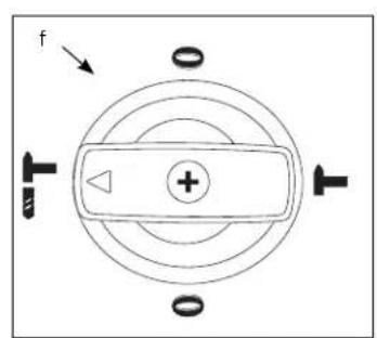
Figure 1A
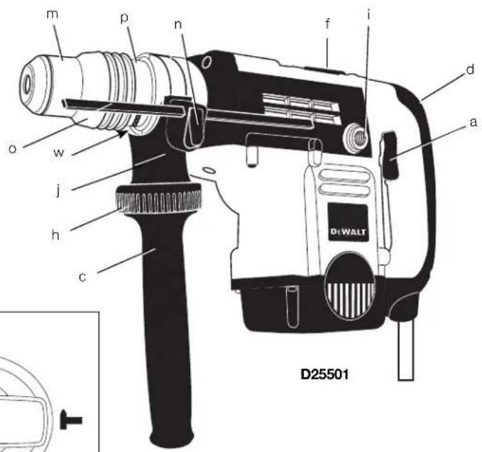
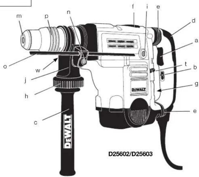
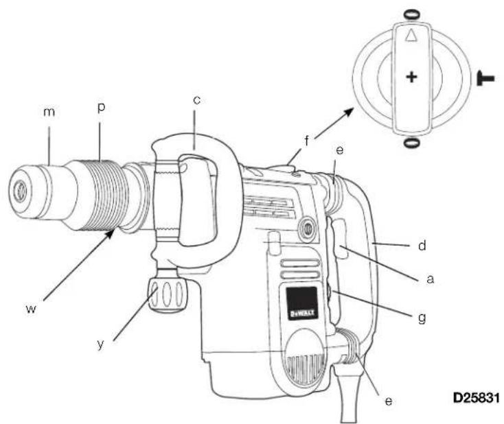
Figure 1B
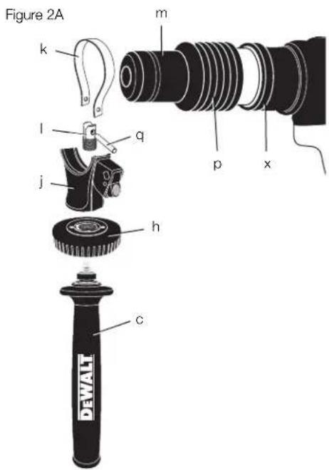
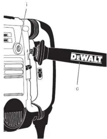
Figure 2B
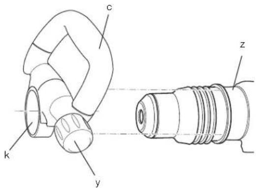
Figure 2C
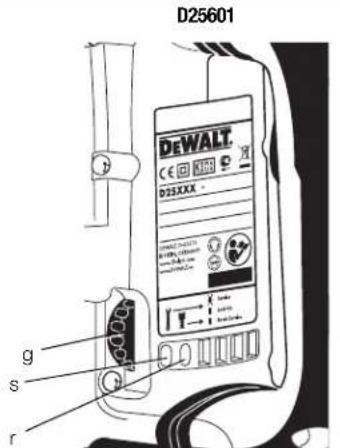
Figure 3

D25603
D25831
SDS MAX® KOMBINATIONS- & MEJSELHAMRE D25501, D25601, D25602, D25603, D25831
Tillykke!
SEL: For at reducere
You have chosen a DEWALT tool. Years of experience, thorough product development and innovation make DEWALT one of the most reliable partners for professional power tool users.
Technical Data
| D25501 | D25601 | D25602 | D25603 | D25831 | ||||||||
| Voltage(V U.K. & Ireland only) | 230230230230230 | 230230230 | V | 230230/115 | 230/115 | 230/115 | 230/115 | 230/115 | 230/115 | 230/115 | ||
| Type | 2 | 2 | 2 | 2 | 2 | 2 | ||||||
| Power input | W | 1100 | 1250 | 1250 | 1250 | 1250 | ||||||
| Impact energy(EPTA 05/2009) | J | 8 | 8 | 8 | 8 | 8 | 8 | |||||
| Total drilling range in concrete: | ||||||||||||
| solid bits | mm | 12-40 | 12-45 | 12-45 | 12-45 | - | ||||||
| core bits | mm | 40-90 | 40-100 | 40-100 | 40-100 | - | ||||||
| Optimum drilling range in concrete: | ||||||||||||
| solid bits | mm | 18-26 | 25-35 | 25-35 | 25-35 | - | ||||||
| Chisel positions | 18 | 18 | 18 | 18 | 18 | |||||||
| Tool holder | SDS Max® | SDS Max® | SDS Max® | SDS Max® | SDS Max® | |||||||
| Weight | kg | 6.15 | 6.8 | 6.9 | 6.95 | 6.1 | ||||||
| L(s), (sound pressure) | dB(A) | 94 | 92 | 93 | 93 | 95 | ||||||
| K(n), (sound pressureuncertainty) | dB(A) | 3 | 3 | 3 | 3 | 3 | ||||||
| L(k), (sound power) | dB(A) | 104 | 103 | 104 | 104 | 106 | ||||||
| K(k), (sound poweruncertainty) | dB(A) | 3 | 3 | 3 | 3 | 3.6 | ||||||
Vibration total values (triax vector sum) determined according to EN 60745:
| Vibration emission value \( a_h \)Drilling into concrete | ||||||
| \( a_{h,HD} = \) | m/s2 | 18.3 | 9.2 | 9.1 | 9.1 | - |
| Uncertainty K = m/s2 | 1.8 | 1.5 | 1.6 | 1.6 | - | |
| Vibration emission value \( a_h \)Chiselling | ||||||
| \( a_{h,Cheq} = \) | m/s2 | 13.2 | 7.2 | 7.4 | 7.4 | 8.3 |
| Uncertainty K = m/s2 | 1.6 | 1.5 | 1.6 | 1.6 | 1.5 | |
The vibration emission level given in this information sheet has been measured in accordance with a standardised test given in EN 60745 and may be used to compare one tool with another. It may be used for a preliminary assessment of exposure.

WARNING: The declared vibration emission level represents the main applications of the tool. However if the tool is used for different applications, with different accessories or poorly maintained, the vibration emission may
ENGLISH
differ. This may significantly increase the exposure level over the total working period.
An estimation of the level of exposure vibration should also take into account the times when the tool is switched off or when it is running but not actually doing the job. This may significantly reduce the exposure level over the total working period.
Identify additional safety measures to protect the operator from the effects of vibration such as: maintain the tool and the accessories, keep the hands warm, organisation of work patterns.
Fuses:
Europe 230 V tools 10 Amperes, mains
U.K. & Ireland 230 V tools 13 Amperes, in plugs
Definitions: Safety Guidelines
The definitions below describe the level of severity for each signal word. Please read the manual and pay attention to these symbols.
DANGER: Indicates an imminently hazardous situation which, if not avoided, will result in death or serious injury.
WARNING: Indicates a potentially hazardous situation which, if not avoided, could result in death or serious injury.
CAUTION: Indicates a potentially hazardous situation which, if not avoided, may result in minor or moderate injury.
NOTICE: Indicates a practice not related to personal injury which, if not avoided, may result in property damage.
damage. Denote risk of electric shock.

EC-DeclarationofConformity
MACHINERY DIRECTIVE

D25501,D25601,D25602,D25603,D25831
DEWALT declares that these products described under "technical data" are in compliance with: 2006/42/EC, EN 60745-1, EN 60745-2-6.
D25831
2000/14/EC Electrical concrete breaker (hand held) m < / = 15kg, Annex VIII: TUV Rheinland Product Safety GmbH (0197), D-51105 Köln, Germany, Notified Body ID No.: 0197
Level of acoustic power according to 2000/14/EC (Article 12, Annex III, No. 10; m < / = 15 kg)
L_WA (measured sound power level) dB 102
Lw (guaranteed sound power level) dB 105
These products also comply with Directive 2004/108/EC. For more information, please contact DEWALT at the following address or refer to the back of the manual.
The undersigned is responsible for compilation of the technical file and makes this declaration on behalf of DEWALT.

Horst Grossmann
Vice President Engineering and Product Development
DEWALT, Richard-Klinger-StraBe 11, D-65510, Idstein, Germany
10.02.2010

WARNING: To reduce the risk of injury, read the instruction manual.
General Power Tool SafetyWarnings
WARNING! Read all safety warnings and instructions. Failure to follow the warnings and instructions may result in electric shock, fire and/or serious injury.
SAVE ALL WARNING AND INSTRUCTIONS FOR FUTURE REFERENCE
The term "power tool" in the warnings refers to your mains-operated (cored) power tool or battery-operated (cordless) power tool.
1) WORK AREA SAFETY
a) Keep work area clean and well lit. Cluttered or dark areas invite accidents.
b) Do not operate power tools in explosive atmospheres, such as in the presence of flammable liquids, gases or dust. Power tools create sparks which may ignite the dust or fumes.
c) Keep children and bystanders away while operating a power tool. Distractions can cause you to lose control.
ENGLISH
2) ELECTRICAL SAFETY
a) Power tool plugs must match the outlet. Never modify the plug in any way. Do not use any adapter plugs with earthed (grounded) power tools. Unmodified plugs and matching outlets will reduce risk of electric shock.
b) Avoid body contact with earthed or grounded surfaces such as pipes, radiators, ranges and refrigerators. There is an increased risk of electric shock if your body is earthed or grounded.
c) Do not expose power tools to rain or wet conditions. Water entering a power tool will increase the risk of electric shock.
d) Do not abuse the cord. Never use the cord for carrying, pulling or unplugging the power tool. Keep cord away from heat, oil, sharp edges or moving parts. Damaged or entangled cords increase the risk of electric shock.
e) When operating a power tool outdoors, use an extension cord suitable for outdoor use. Use of a cord suitable for outdoor use reduces the risk of electric shock.
If operating a power tool in a damp location is unavoidable, use a residual current device (RCD) protected supply. Use of an RCD reduces the risk of electric shock.
3) PERSONAL SAFETY
a) Stay alert, watch what you are doing and use common sense when operating a power tool. Do not use a power tool while you are tired or under the influence of drugs, alcohol or medication. A moment of inattention while operating power tools may result in serious personal injury.
b) Use personal protective equipment. Always wear eye protection. Protective equipment such as dust mask, non-skid safety shoes, hard hat, or hearing protection used for appropriate conditions will reduce personal injuries.
c) Prevent unintentional starting. Ensure the switch is in the off position before connecting to power source and/or battery pack, picking up or carrying the tool. Carrying power tools with your finger on the switch or energising power tools that have the switch on invites accidents.
d) Remove any adjusting key or wrench before turning the power tool on. A wrench or a key left attached to a rotating part of the power tool may result in personal injury.
e) Do not overreach. Keep proper footing and balance at all times. This enables better control of the power tool in unexpected situations.
) Dress properly. Do not wear loose clothing or jewellery. Keep your hair, clothing and gloves away from moving parts. Loose clothes, jewellery or long hair can be caught in moving parts.
g) If devices are provided for the connection of dust extraction and collection facilities, ensure these are connected and properly used. Use of dust collection can reduce dust-related hazards.
4) POWER TOOL USE AND CARE
a) Do not force the power tool. Use the correct power tool for your application. The correct power tool will do the job better and safer at the rate for which it was designed.
b) Do not use the power tool if the switch does not turn it on and off. Any power tool that cannot be controlled with the switch is dangerous and must be repaired.
c) Disconnect the plug from the power source and/or the battery pack from the power tool before making any adjustments, changing accessories, or storing power tools. Such preventive safety measures reduce the risk of starting the power tool accidentally.
d) Store idle power tools out of the reach of children and do not allow persons unfamiliar with the power tool or these instructions to operate the power tool. Power tools are dangerous in the hands of untrained users.
e) Maintain power tools. Check for misalignment or binding of moving parts, breakage of parts and any other condition that may affect the power tool's operation. If damaged, have the power tool repaired before use. Many accidents are caused by poorly maintained power tools.
) Keep cutting tools sharp and clean. Properly maintained cutting tools with sharp cutting edges are less likely to bind and are easier to control.
g) Use the power tool, accessories and tool bits etc., in accordance with these instructions taking into account the working conditions and the work to be performed. Use of the power tool for operations different from those intended could result in a hazardous situation.
ENGLISH
5) SERVICE
a) Have your power tool serviced by a qualified repair person using only identical replacement parts. This will ensure that the safety of the power tool is maintained.
Additional Safety Instructions for Rotary Hammers
- Wear ear protectors. Exposure to noise can cause hearing loss.
- Use auxiliary handle(s), if supplied with the tool. Loss of control can cause personal injury.
- Hold power tool by insulated gripping surfaces, when performing an operation where the cutting accessory may contact hidden wiring or its own cord. Cutting accessory contacting a "live" wire may make exposed metal parts of the power tool "live" and could give the operator an electric shock.
Residual Risks
The following risks are inherent to the use of rotary and chipping hammers:
Injuries caused by touching the rotating parts or hot parts of the tool
In spite of the application of the relevant safety regulations and the implementation of safety devices, certain residual risks cannot be avoided. These are:
Impairment of hearing.
- Risk of squeezing fingers when changing the accessory.
Health hazards caused by breathing dust developed when working in concrete and/or masonry.
Markings on Tool
The following pictograms are shown on the tool:

Read instruction manual before use.

Wear ear protection.

Wear eye protection.

Clutch Setting 40 Nm is designed for most drilling applications

Clutch Setting 80 Nm is designed for higher torque applications

Red service indicator LED. For detailed description see under Service Indicator LED's.

Yellow service indicator LED. For detailed description see under Service Indicator LED's.
DATE CODE POSITION (FIG.1)
The Date Code (w), which also includes the year of manufacture, is printed into the housing.
Example:
2011 XX XX
Year of Manufacture
Package Contents
The package contains:
1 Rotary hammer (D25501, D25601, D25602, D25603) or
1 Chipping hammer (D25831)
1 Side handle
1 Kitbox (K-models only)
1 Instruction manual
1 Exploded drawing
- Check for damage to the tool, parts or accessories which may have occurred during transport.
Take the time to thoroughly read and understand this manual prior to operation.
Description (fig. 1A, 1B, 2A-C)

WARNING: Never modify the power tool or any part of it. Damage or personal injury could result.
a. Trigger switch (D25501, D25601, D25602, D25603)
On/off rocker switch (D25831)
b. Lock-on slider (D25601, D25602, D25603)
c. Side handle
d. Main handle
e. Active vibration control (D25601, D25602, D25603, D25831)
f.Mode selector switch
g. Electronic speed and impact control dial (D25601, D25602, D25603, D25831)
h. Clamp wheel
ENGLISH
i. Rear side handle position
j. Side handle clamp
k. Steel ring
I. Bush
m. Tool holder
n. Depth rod release button
o. Depth rod
p. Locking sleeve
q. Pin
x. Collar
y. Side handle knob
INTENDED USE
D25501, D25601, D25602, D25603
Your rotary hammer has been designed for professional rotary drilling and chipping applications.
D25831
Your chipping hammer has been designed for professional chipping, chiselling and demolition applications.
DO NOT use under wet conditions or in presence of flammable liquids or gases.
These hammers are professional power tools.
DO NOT let children come into contact with the tool. Supervision is required when inexperienced operators use this tool.
Soft Start Feature
D25601, D25602, D25603, D25831
The soft start feature allows the speed to build up speed slowly, thus preventing the drill bit from walking off the intended hole position when starting.
The soft start feature also reduces the immediate torque reaction transmitted to the gearing and the operator if the hammer is started with the drill bit in an existing hole.
Electronic Speed and Impact Control (fi g. 1, 3)
D25601, D25602, D25603, D25831
The electronic speed and impact control (g) offers the following advantages:
- use of smaller accessories without risk of breakage;
- minimised break-out when chiselling or drilling in soft or brittle materials;
- optimal tool control for precise chiselling.
Torque Limiting Clutch
The torque limiting clutch reduces the maximum torque reaction transmitted to the operator in case of jamming of a drill bit. This feature also prevents the gearing and electric motor from stalling. The torque limiting clutch has been factory-set and cannot be adjusted.
Complete Torque Control (fi g. 3)
D25602, D25603
NOTICE: Always turn the tool off before changing torque control settings or damage to tool may result.
The Complete Torque Control (CTC) feature of this tool is designed to provide additional control with a two-stage clutch mechanism. Refer to Setting the Torque Control Switch for more information.
Adaptive Drill Contol (ADC)
D25603 (FIG. 3)
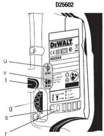
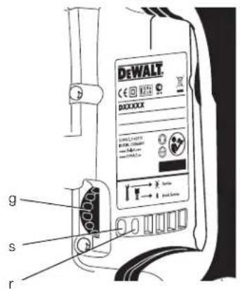
The D25603 is equipped with an adaptive drill control. This feature senses the motion of tool and reduces the motor torque to a manageable level if necessary. The red indicator LED (r) will illuminate to indicate status.
NOTE: If tool power is insufficient for normal drilling and the red LED indicator does not flash, take the tool to an authorized DEWALT repair center.
Service Indicator LEDs (fi g. 3)
D25601, D25602, D25603, D25831
The yellow brushwear indicator LED (s) lights up when the carbon brushes are nearly worn out to indicate that the tool needs servicing within the next 8 hours of use.
D25601, D25602, D25603
The red service indicator LED (r) lights up if the lock-on button (b) is used in any mode except the chipping mode. In all models with the adaptive drill control (ADC), the red indicator LED (r) lights up if the ADC is engaged. The red indicator starts to flash if there is a fault with the tool or the brushes have completely worn out (refer to Brushes under
Maintenance).
D25831
The red service indicator LED (r) lights up if there is a fault with the tool or the brushes have completely worn out (refer to Brushes under Maintenance).
Fully Vibration-dampened Main Handle (fi g. 1)
D25601, D25602, D25603, D25831
The dampers in the side handle (c) absorb the vibrations transmitted to the user. This improves user comfort during the operation.
Electrical Safety
The electric motor has been designed for one voltage only. Always check that the power supply corresponds to the voltage on the rating plate.

Your DEWALT tool is double insulated in accordance with EN 60745; therefore no earth wire is required.

NG: 115 V units have to be operated via a fail-safe isolating transformer with an earth screen between the primary and secondary winding.
If the supply cord is damaged, it must be replaced by a specially prepared cord available through the DEWALT service organisation.
Mains Plug Replacement (U.K. & Ireland Only)
If a new mains plug needs to be fitted:
- Safely dispose of the old plug.
- Connect the brown lead to the live terminal in the plug.
- Connect the blue lead to the neutral terminal.

VG: No connection is to be made to the earth terminal.
Follow the fitting instructions supplied with good quality plugs. Recommended fuse: 13 A.
Using an Extension Cable
If an extension cable is required, use an approved 3-core extension cable suitable for the power input of this tool (see technical data). The minimum conductor size is 1.5mm^2 ; the maximum length is 30m .
When using a cable reel, always unwind the cable completely.
ASSEMBLY AND ADJUSTMENTS
WARNING: To reduce the risk of injury, tum unit off and
injury, turn unit off and disconnect machine from power source before installing and removing accessories,
before adjusting or changing setup or when making repairs. Be sure the trigger switch is in the OFF position. An accidental start-up can cause injury.
WARNING: Tool bits may be hot and gloves should be worn when changing or removing them to avoid personal injury.
Assembling and Fitting the Side Handle (fi g. 2A, 2B)
The side handle (c) can be mounted in front or in rear position on either side of the machine to suit both RH- and LH-users.

IG: Always operate the tool with the side handle properly assembled.
D25501, D25601, D25602, D25603
MOUNTING IN FRONT POSITION (FIG. 2A)
- Snap the steel ring (k) over the collar (x) behind the tool holder (m). Squeeze both ends together, mount the bush (l) and insert the pin (q).
- Place the side handle clamp (j) and screw on the clamp wheel (h). Do not tighten.

WARNING: Once assembled, the side handle clamp should never be removed.
- Screw the side handle (c) into the bush (l) and then into clamp wheel. Tighten securely.
- Rotate the side handle mounting assembly to the desired position. For drilling horizontally with a heavy drill bit, we recommend to place the side handle at an angle of approx. 20^ for optimum control.
- Lock the side handle mounting assembly in place by tightening the clamp wheel (h).
MOUNTING IN REAR POSITION (FIG. 2B)
The rear position is particularly useful when drilling down into a floor.
- Unscrew the side handle (c) and remove it from the front position. Leave the side handle mounting assembly in front position.
- Screw the side handle directly into one of the rear side handle positions (i) on either side of the tool.
D25831 (FIG. 2C)
- Unscrew the side handle knob (y).
- Slide the side handle assembly onto the machine locating the steel ring (k) in the
ENGLISH
mounting area (z). The correct position of the side handle is between head and middle of the tube.
- Adjust the side handle (c) to the desired angle.
- Slide and rotate the side handle to the desired position.
- Lock the side handle in place by tightening the knob (y).
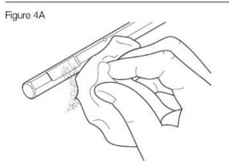
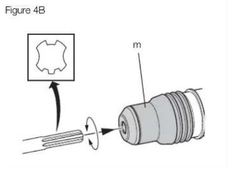
Inserting and Removing SDS Max® Accessories (fig. 1, 4A, 4B)
This machine uses SDS Max® bits and chisels (refer to the inset in figure 4B for a cross-section of an SDS Max® bit shank).
- Clean the bit shank.
- Pull back the locking sleeve (p) and insert the bit shank.
- Turn the bit slightly until the sleeve snaps into position.
- Pull on the bit to check if it is properly locked. The hammering function requires the bit to be able to move axially several centimetres when locked in the tool holder.
- To remove a bit pull back the tool holder locking sleeve/collar (p) and pull the bit out of the tool holder.
Selecting the Operating Mode (fi g. 1)
T
Hammerdrilling: D25501, D25601, D25602, D25603 for concrete, brick, stone and masonry drilling operations.
T
Hammering only: D25501, D25601, D25602, D25603, D25831
for chiselling and demolition applications. In this mode the tool can also be used as a lever to free a jammed drill bit.
- To select the operating mode, rotate the mode selector switch (f) until it points to the symbol of the required mode.
It may be necessary to twist the tool holder (m) slightly to allow the mode selector switch (f) to pass the position. - Check that the mode selector switch (f) is locked in place.
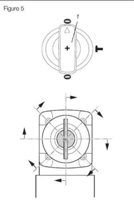
Indexing the Chisel Position (fi g. 5)
D25501, D25601, D25602, D25603, D25831
The chisel can be indexed and locked into 18 different positions.
- Rotate the mode selector switch (f) until it points towards the 0 position.
- Rotate the chisel in the desired position.
- Set the mode selector switch (f) to the "hammering only" position.
- Twist the chisel until it locks in position.
Setting the Electronic Speed and Impact Control Dial (fig. 1, 3)
D25601, D25602, D25603, D25831
Turn the dial (g) to the desired level. Turn the dial upwards for higher speed and downwards for lower speed. The required setting is a matter of experience. E.g.:
- when chiselling or drilling in soft, brittle materials or when minimum break-out is required, set the dial to a low setting;
when breaking or drilling in harder materials, set the dial to a high setting.
Setting the Torque Control Switch (fi g. 3)
D25602, D25603
NOTICE: Always turn the tool off before changing torque control settings or damage to the tool may result.
Move the torque control lever (t) to setting 40 Nm or 80 Nm as needed for application.
Clutch Setting 40 Nm (u) is designed for most drilling applications and is designed to easily clutch out when the drill bit encounters re-bar or other foreign substances.
Clutch Setting 80 Nm (v) is designed for higher torque applications such as corebits and deep hole drilling and is designed to clutch out at a higher torque threshold.
NOTE: Allow the motor housing to rotate a little while changing torque.
Each time the tool is plugged in, it will automatically default to clutch setting 1 into clutch setting 40Nm (u), the most sensitive setting.
Depth Rod (fi g. 1)
D25501, D25601, D25602, D25603
TO ADJUST THE DEPTH ROD
- Push in and hold the depth rod release button (n) on the side handle.
- Move the depth rod (o) so the distance between the end of the rod and the end of the bit equals the desired drilling depth.
- Release the button to lock rod into position. When drilling with the depth rod, stop when end of rod reaches surface of material.
OPERATION
Instructions for Use
WARNING: Always observe the safety instructions and applicable regulations.
WARNING: To reduce the risk
of serious personal injury, turn tool off and disconnect tool from power source before making any adjustments or removing/installing attachments or accessories.

WARNING: Tool bits may be hot and gloves should be worn when changing or removing them to avoid personal injury.

Be aware of the location of pipework and wiring.
- Apply only a gentle pressure to the tool (approx. 20kg ). Excessive force does not speed up drilling but decreases tool performance and may shorten tool life.
Always hold the tool firmly with both hands and ensure a secure stance. Always operate the tool with the side handle properly assembled.
NOTE: Operating temperature is (-7 to +40°C (19° to 104°F). Using the tool outside of this temperature range will decrease the life of the tool.
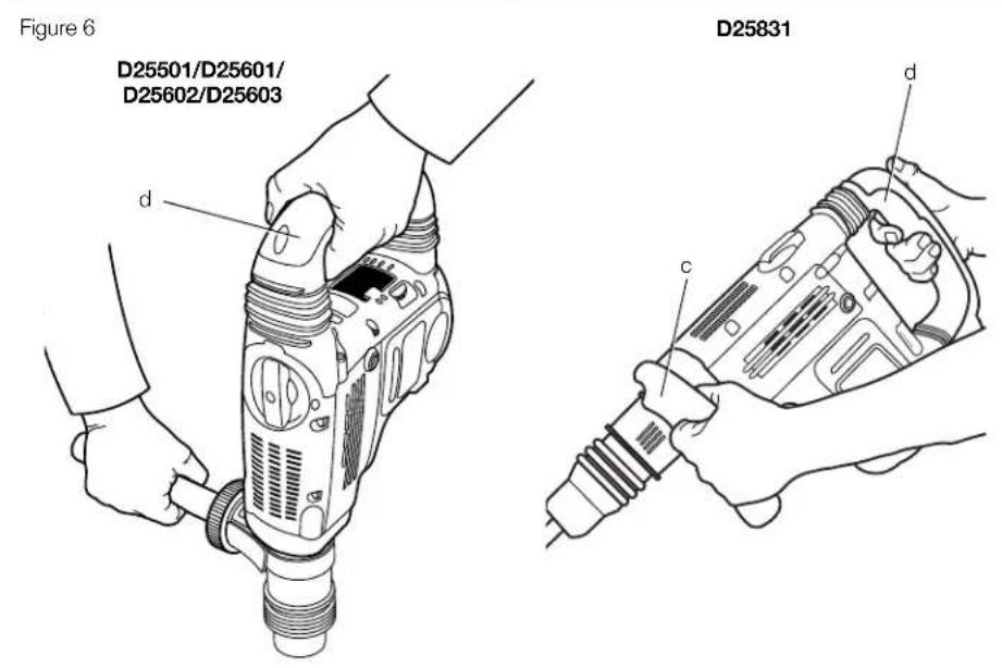
Proper Hand Position (fi g. 6)
WARNING: To reduce the risk of serious personal injury, ALWAYS use proper hand position as shown.
WARNING: To reduce the risk of serious personal injury, ALWAYS hold securely in anticipation of a sudden reaction.
Proper hand position requires one hand on the side handle (c), with the other hand on the main handle (d).
Switching On and Off (fi g. 1)
D25501, D25601, D25602, D25603
To turn the tool on, depress the trigger switch (a).
To stop the tool, release the trigger switch.
D25601, D25602, D25603
The lock-on slider (b) allows the trigger switch (a) to be locked on in chiselling mode only. If the lock-on button is activated in drilling mode, as a feature the tool will switch off automatically.
To turn the tool on, press the trigger switch (a).
To stop the tool, release the switch.
For continuous operation, press and hold down the switch (a), slide the lock-on button (b) upwards and release the switch.
To stop the tool in continuous operation, press the switch briefly and release it. Always switch off the tool when work is finished and before unplugging.
D25831
To turn the tool on, press the on/off rocker switch (a) at the lower part of the trigger.
To stop the tool, press the on/off rocker switch at the upper part of the trigger.
Hammerdrilling
To turn the tool on, press the on/off switch (a).
To stop the tool, release the switch.
Drilling with a Solid Bit (fi g. 1)
D25501, D25601, D25602, D25603
- Insert the appropriate drill bit.
- Set the mode selector switch (f) to the hammerdrilling position.
- D25601, D25602, D25603 only: Set the electronic speed and impact control dial (g).
- Fit and adjust the side handle (c).
- Mark the spot where the hole is to be drilled.
- Place the drill bit on the spot and switch on the tool.
- Always switch off the tool when work is finished and before unplugging.
Drilling with a Core Bit (fi g. 1)
- Insert the appropriate core bit.
- Assemble the centerdrill into the core bit.
ENGLISH
- Set the mode selector switch (f) to the hammerdrilling position.
- D25601, D25602, D25603 only: Turn the electronic speed and impact control dial (g) to a medium or high speed setting.
- Fit and adjust the side handle (c).
- Place the centerdrill on the spot and switch on the tool. Drill until the core penetrates into the concrete approx. 1 cm.
- Stop the tool and remove the centerdrill. Place the core bit back into the hole and continue drilling.
- When drilling through a structure thicker than the depth of the core bit, break away the round cylinder of concrete or core inside the bit at regular intervals.
To avoid unwanted breaking away of concrete around the hole, first drill a hole the diameter of the centerdrill completely through the structure. Then drill the cored hole halfway from each side - Always turn the tool off when work is finished and before unplugging.
Chipping and Chiselling (fi g. 1)
D25501, D25601, D25602, D25603, D25831
- Insert the appropriate chisel and rotate it by hand to lock it into one of 18 positions.
- Set the mode selector switch (f) to the hammering only position.
- D25601, D25602, D25603, D25831 only: Set the electronic speed and impact control dial (g).
- Fit and adjust the side handle (c).
- Turn the tool on and start working.
- Always turn the tool off when work is finished and before unplugging.
MAINTENANCE
Your DEWALT power tool has been designed to operate over a long period of time with a minimum of maintenance. Continuous satisfactory operation depends upon proper tool care and regular cleaning.
WARNING: To reduce the risk of injury, turn unit off and disconnect machine from power source before installing and removing accessories, before adjusting or changing setups or when making repairs. Be sure the trigger switch is in the OFF position. An accidental start-up can cause injury.
This machine is not user-serviceable. Take the tool to an authorised DEWALT repair agent after
approximately 150 hours of use. If problems occur before this time contact an authorised DEWALT repair agent.
Brushes (fi g. 3)
The carbon brushes are not user-serviceable. Take the tool to an authorized DEWALT repair agent.
The yellow brushwear indicator LED (r) lights up when the carbon brushes are nearly worn out. After a further 8 hours of use or after the brushes have completely worn out the motor will automatically be shut off.
Tool maintenance needs to be carried out as soon as the service indicator (s) lights up.

Lubrication
Your power tool requires no additional lubrication.

Cleaning
WARNING: Blow dirt and dust out of the main housing with dry air as often as dirt is seen collecting in and around the air vents. Wear approved eye protection and approved dust mask when performing this procedure.
WARNING: Never use solvents or other harsh chemicals for cleaning the non-metallic parts of the tool. These chemicals may weaken the materials used in these parts. Use a cloth dampened only with water and mild soap. Never let any liquid get inside the tool; never immerse any part of the tool into a liquid.
Optional Accessories
WARNING: Since accessories, other than those offered by DEWALT, have not been tested with this product, use of such accessories with this tool could be hazardous. To reduce the risk of injury, only DEWALT, recommended accessories should be used with this product.
Various types of SDS Max® drill bits and chisels are available as an option.
Consult your dealer for further information on the appropriate accessories.
Protecting the Environment
Separate collection. This product must not be disposed of with normal household waste.
Should you find one day that your DEWALT product needs replacement, or if it is of no further use to you, do not dispose of it with household waste. Make this product available for separate collection.

Separate collection of used products and packaging allows materials to be recycled and used again. Re-use of recycled materials helps prevent environmental pollution and reduces the demand for raw materials.
Local regulations may provide for separate collection of electrical products from the household, at municipal waste sites or by the retailer when you purchase a new product.
DEWALT provides a facility for the collection and recycling of DEWALT products once they have reached the end of their working life. To take advantage of this service please return your product to any authorised repair agent who will collect them on our behalf.
You can check the location of your nearest authorised repair agent by contacting your local DEWALT office at the address indicated in this manual. Alternatively, a list of authorised DEWALT repair agents and full details of our after-sales service and contacts are available on the Internet at: www.2helpU.com.
GUARANTEE
DEWALT is confident of the quality of its products and offers an outstanding guarantee for professional users of the product. This guarantee statement is in addition to and in no way prejudices your contractual rights as a professional user or your statutory rights as a private non-professional user. The guarantee is valid within the territories of the Member States of the European Union and the European Free Trade Area.
30 DAY NO RISK SATISFACTION GUARANTEE
If you are not completely satisfied with the performance of your DEWALT tool, simply return it within 30 days, complete with all original components, as purchased, to the point of purchase, for a full refund or exchange. The product must have been subject to fair wear and tear and proof of purchase must be produced.
- ONE YEAR FREE SERVICE CONTRACT
If you need maintenance or service for your DEWALT tool, in the 12 months following purchase, you are entitled to one service free of charge. It will be undertaken free of charge at an authorised DEWALT repair agent. Proof of purchase must be produced. Includes labour. Excludes accessories and spare parts unless failed under warranty.
- ONE YEAR FULL WARRANTY
If your DEWALT product becomes defective due to faulty materials or workmanship within 12 months from the date of purchase, DEWALT guarantees to replace all defective parts free of charge or - at our discretion - replace the unit free of charge provided that:
The product has not been misused;
The product has been subject to fair wear and tear.
- Repairs have not been attempted by unauthorised persons;
Proof of purchase is produced.
The product is returned complete with all original components
If you wish to make a claim, contact your seller or check the location of your nearest authorised DEWALT repair agent in the DEWALT catalogue or contact your DEWALT office at the address indicated in this manual. A list of authorised DEWALT repair agents and full details of our after-sales service is available on the Internet at: www.2helpU.com
ESPANOL
MARTILLOS SDS MAX® COMBINACION Y MARTILLOS DE SOLDADOR D25501, D25601, D25602, D25603, D25831
Enhorabuena!
ADVERTENCIA: Jamas use disolventes u或者其他 produits químicos fuertes para limiar las piezas no metálicas de la heramienta. Dichos produits químicosSEOSEOSEOSEOSEOSEOSEOSEOSEOSEOSEOSEOSEOSEOSEOSEOSEOSEOSEOSEOSEOSEOSEOSEOSEOSEOSEOSEOSEOSEOSEOSEOSEOSEOSEOSEOSEOSEOSEOSEOSEOSEOSEOSEOSEOSEOSEOSEOSEOSEOSEOSEOSEOSEOSEOSEOSEOSEOSEOSEOSEOSEOSEOSEOSEOSEOSEOSEOSEOSEOSEOSEOSEOSEOSEOSEOSEOSEOSEOSEOSEOSEOSEOSEOSEOSEOSEOSEOSEOSEOSEOSEOSEOSEOSEOSEOSEOSEOSEOSEO SEOEO SEOEO SEOEO SEOEO SEOEO SEOEO SEOEO SEOEO SEOEO SEOEO SEOEO SEOEO SEOEO SEOEO SEOEO SEOEO SEOEO SEOEO SEOEO SEOEO SEOEO SEOEO SEOEO SEOEO SEOEO SEOEO SEOEO SEOEO SEOEO SEOEO SEOEO SEOEO SEOEO SEOEO SEOEO SEOEO SEOEO SEOEO SEOEO SEOEO SEOEO SEOEO SEOEO SEOEO SEOEO SEOEO SEOEO SEOEO SEOEO SEOEO SEOEQ

BEWAAR ALLE WAARSCHUWINGEN EN INSTRUCTIES ALS TOEKOMSTIG REFERENTIEMATERIALAAL
POSITIE DATUMCODE (AFB. [FIG.] 1)
Service-indicatie-LED's (afb. 3)
D25601, D25602, D25603, D25831
Borster under Vedlikehold.
D25831
Den rode LED servicelampen (r) tennes dersom det er en feil ved verktoyet aller borstene er fullstendig utslitte (se Borster under Vedlikehold).
Horst Grossmann
Vice President Engineering and Product Development
DEWALT, Richard-Klinger-Strasse 11, D-65510, Idstein, Germany
10.02.2010

PAIVAMARAKOODIN SIJAINTI (KUVA [FIG.1]
DATUMKODPLACERING (FIG.1)
AuxviEcLED evdEiEgσepic (EK.3)
D25601, D25602, D25603, D25831
H KITPIV N AUYVALED EVDIEIGNS PHTOPW (s) avaei otav n yktpes avpaka exouv oxedov aepie, ia va onlaowei on to evayaleo xpeiaetai oepic meo aotic etrovee 8 wpcxipn.
D25601, D25602, D25603
H Kokivn Auxvia LED evdeis n oepic (avabei av to Koumtia aopafaiionc ole aeitoupyia (b) xpnootoinei oe otioaidnote aaan aeitoupyia ekoc tsn atoletinc. Se ola ta movtea me TPooapooTiko eayxo tputtaviou (ADC), n Kokivn evdeikn Auxvia LED (r) avabei av exei eutakei o ADC.H Kokivn evdeikn Auxvia apixei va avoobnvei av utapxeiTPOBAnmu e To epyaieio n av oiNktpecexouv phapei TEAEIWc (avatpeEte OTo Tmua Nktpec ts Evotntac Euvtnpon).
D25831
H KOKIVn Luxvia LED eoi ng oepic (r) avaei av utapxei npalmae to epyaleio n av oi knptec exouv phapei teaiwos (avatpeTe OTO tnaa (\Psi \kappa \kappa \kappa \kappa \kappa \kappa \kappa \kappa \kappa \kappa \kappa \kappa \kappa \kappa \kappa \kappa \kappa \kappa \kappa \kappa \kappa \kappa \kappa \kappa \kappa \kappa \kappa \kappa \kappa \kappa \kappa \kappa \kappa \kappa
Kupia aTROBcON KpaDaaMuV (EK.1)
D25601, D25602, D25603, D25831
Oi aotoaeeotnpesntn Taeupikn AaBn (c)
atoppoouv Toukpaadouc Tou metabiodovta
oto xphtn. Etoi Baeliwetai n aveon Tou xphtn
kata t naitoupyia.
Hλεκτρικήσαφάλεια
O nkekptikoc kivtnpac exi oxediataei yia
aetoupyia mvo oe ia taon. Eexyete ravtoTe
eav n Tpoopooia avtatokpiveta tny taon Tou
aaypapetai otnv eTIVpaqn me Ta doeuva.

To epyaaleio TNS DEWALT diaheTei dttAn own ouqwva u To potutTO EN 60745. KaTouveTieia, dev aataeTai kalwoio veiowns
Eav to kaawio tropobodiaac uttoei
Baa, npetie va atikataatae iatio Eioka
diapopwveo kawio tou diatietai meow ts
utnpesiae egunnpentnns nds DEWALT.
Xpno npoektaonc
Av aataeirai kalwio etektao, xpoiotoinote
eykepiévo kalwio etektao 3 aywyov
katalnaio yia tvv ixu autou tou epyaieou
( texvika o6oeva.To eaxio to meyeboc tou ayowyouivai 1.5 mm2, evw to myioto mkoic ivai 30m.
Otvx npoioutoieTe Kaawioe poAo, va Sctuivety TAVTOTE TO Kaawio Evteawc.
SYNAPMOAOHSH KAI PYOMIIEI

IPOEIOIHsH:ia va eioe Tov Kivduvo Tpaumaoou, anevpyoiojote novada kai aoosuvdeote toxavna ato tvn npuatoC priv nV ekataoan kai npaipoe aneouap, piv tn puboian nTnv alayn diapoqwns napaeptpw nOtav exkaleite emokvecs. Bebaowtei oti oiaokntcakavda n evai otn thane atevpyoioianc. Tuxov aBentn ekkivan mtopevi va npokaleei tpaumaiio.

NPOEIANOIHs: Ta KOTNIKA TOU epyaleiou mtopei va eivai eepka kai yi auto npetie va qopate yavnia otav ta aaaaTe n ta apaipeire, wote va atropuyete oomegaatikn bia.
Suvapuoloynon kai ttooettnon tns nAeupikncs (EIK.2A,2B)
H TIAEUPIKIaBc) mTOpei va totoTeNtEi OE tPOOTIVnOE TiOW ΕeON OE oTIOAIDNTOTE TIAEUPaTO uXavmAtoc WATE VA TAPIACEI TOO O EDEIXOPECS 000 KAI OE apiotePOxIEPc XpntEs.

IPOEIONOIHsH: Nava Xpnoiortoe to epyaleio TnV tAevipnAafn oWota ouvapuoloyneV.
D25501, D25601, D25602, D25603
TOIOOETHsH ΣE MINToSTINH OEsH (EIK. 2A)
- Nepaote To xaUboivo DakTuio (k) Tavw ato To KoApo (x) Tiow ato TIV UTOOxN aEeouap (m). ZumTIOeTo Ta duo akpa, TOTOBETnTe TOV DakTuio MetabaoNc (I) KAI EIAyEToTov TEipo (q).
- ToTTOBETHOte TO aOPIYKTnpa (j) TNS TIAEUPIKNc AaBns Ka BIOwote TAVW TOV TPOXo OUOPIeNs (h).Mn oipieTe.

IPOEIODOIHsH:Orav ouvapmooyoynei, o apykrnpac TaeupkiC aBrc δev npertie va apapeoietote.
-
Biodote TnV TAAupikh AaBc (C) OTo BaKTUALoTaaonC (I) KAI KATOTIV OTov TPOXO SuqpiNs. ZpEe KaHa.
-
Nepiatpeyote OTN VETIthuuntn theon To OuykpOtnma TOTOBtPnC nTIS TAEupikns AaBns. Ia opizovia diatponn me Bapu KOTNIKO diatponns, ouviotoume va TOTOBteITE TIV TAEupiknAaBn e yuvia tep. 20^ vla va ETTUXETE BATEIOEYEYO.
5.Aoqaiote otn theou to ouykpotnau TOnotheTnns Tneuupikns Aabns Ouaipyyovtacovtpoxo uoepi(c)h).
TONOOTHEHSEI OEH (EIK.2B)
H maw 0eon evai idaetepa xnoun otav n diatpnoyivetaKw npoc eva dnteto.
- EbiowTe TnV TIAEUPIKn AaBn (c) KAI aepieTe Tnv atro n mTPOoTIVn Thea ApnoTE TO OuyKpOtnua ToTIOBETnns TNS TIAEUPIKn AaBn OTNV mTPOoTIVn Thea
- Biodote Tny TAEUPKn AaBn ATuE uEeiaC e Mi aTTO TIO W EOEIS TAEUPKns AaBn (i) Oe Mi aTTO TIO DUO TAEUPcTou Epyaeiou.
D25831 (EIK. 2C)
- EβiδωeTO kouμTI TlAeupikns λαβns (y).
- NepaTe TouykpOtnma TAnepiKns AaHs
Tavw OTo mXavnma ToTOBETWvTaC TO
XaUbDIO BAKTUIO (k) OTN TEPIOXn
TTOBtEnoNc (z). H OwOn Theon TnS TAnepiKn
AaHs Eiva avaeca OTo N KepaAn Kai Toeov
Tou Owlnva.
3.PuOJIATE NTV TIAeupikn AaBn (c) OTNv EITIOUHTYwVia. - Περαστε KAI Περιορεμετην Πλευρική λαβή Στην επθυμιπή θεση.
5.Aoapaiote otn theon tnc nTv Tneupikn laa n ouapivyovtac to koupti (y).
Eioaywn kai aphaipoeon p tuTou SDS Max (EK.1,4A,4B)
To npxavnma auto xnpaioTIOei KOTTIKA KAI OJIAEs TUTOU SDS Max (avatpeE TE OTO EVeTeO OTNv EIKOVA 4B OXETIKA ME TBIATou Tou KOPou Evoc KOTTIKOU SDS Max).
- Na exete utoyn oac tn theon wv ownywoewov kai kalwioewv.
Epaipocete mvo elaqpa tian oTo epyaieo (nep.20 kg).H utepboaiki duvaui nve mtaxovri diatpon aalaeiweinntaoon tou epyaioe kai tpoei va eiwoe to XpOvo cwnc Tou.
Flavata kparate to epyaleio otahepa ka tao xepia kai eaoqali cate euataon taon tou ouawatoc sae. Flavata xpanoitoeite to epyaleio me tvn Taeupikn Abn owata ouvapuoynmev n.
EHMEIOsH: H eepoKpaia aeitoupyiac evai (-7 ews +40C (19'ewc 104F).H xpnoTou epyaieou ktoac autnc Tnpiioxns eepoKpaiaWv eioe to xpovzwns tou.
Tia va otapatnoet To epyaaleio, aipote to 0iakottn.
Tia ouvexn aeitoupyla, TIOE KA KpatnoTE
TATnuevo To biakottn (a), OUPETe KOUPTI
aOAPALIONC OE AEIToupyla (b) KA ATTEAEUtheta TO
biakottn.
Tia va otapatnoeteto epyaleio otaiv elae ouvexn aeoupyia, TIOe Ouvtoa to diakottn kai euehepeoate To. Nava attevepyotoiieTo epyaleio oTav TEAEiOe i np yaoia kai TIPV TO aTOOUVEOeTe ATO THI PICA.
EAAHNIKA
D25831


- SDS MAX® KOMBINATIONS- & MEJSELHAMRE D25501, D25601, D25602, D25603, D25831
- Tillykke!
- ENGLISH
- Fuses:
- Definitions: Safety Guidelines
- EC-DeclarationofConformity
- D25831
- General Power Tool SafetyWarnings
- SAVE ALL WARNING AND INSTRUCTIONS FOR FUTURE REFERENCE
- 1) WORK AREA SAFETY
- 2) ELECTRICAL SAFETY
- 3) PERSONAL SAFETY
- 4) POWER TOOL USE AND CARE
- 5) SERVICE
- Additional Safety Instructions for Rotary Hammers
- Residual Risks
- Markings on Tool
- DATE CODE POSITION (FIG.1)
- Package Contents
- Description (fig. 1A, 1B, 2A-C)
- INTENDED USE
- D25501, D25601, D25602, D25603
- Soft Start Feature
- D25601, D25602, D25603, D25831
- Electronic Speed and Impact Control (fi g. 1, 3)
- Torque Limiting Clutch
- Complete Torque Control (fi g. 3)
- D25602, D25603
- Adaptive Drill Contol (ADC)
- D25603 (FIG. 3)
- Service Indicator LEDs (fi g. 3)
- D25601, D25602, D25603
- Maintenance).
- Fully Vibration-dampened Main Handle (fi g. 1)
- Electrical Safety
- Mains Plug Replacement (U.K. & Ireland Only)
- Using an Extension Cable
- ASSEMBLY AND ADJUSTMENTS
- Assembling and Fitting the Side Handle (fi g. 2A, 2B)
- MOUNTING IN FRONT POSITION (FIG. 2A)
- MOUNTING IN REAR POSITION (FIG. 2B)
- D25831 (FIG. 2C)
- Inserting and Removing SDS Max® Accessories (fig. 1, 4A, 4B)
- Selecting the Operating Mode (fi g. 1)
- Indexing the Chisel Position (fi g. 5)
- Setting the Electronic Speed and Impact Control Dial (fig. 1, 3)
- Setting the Torque Control Switch (fi g. 3)
- Depth Rod (fi g. 1)
- OPERATION
- Instructions for Use
- Proper Hand Position (fi g. 6)
- Switching On and Off (fi g. 1)
- Hammerdrilling
- Drilling with a Solid Bit (fi g. 1)
- Drilling with a Core Bit (fi g. 1)
- Chipping and Chiselling (fi g. 1)
- D25501, D25601, D25602, D25603, D25831
- MAINTENANCE
- Brushes (fi g. 3)
- Lubrication
- Cleaning
- Optional Accessories
- Protecting the Environment
- GUARANTEE
- DAY NO RISK SATISFACTION GUARANTEE
- - ONE YEAR FREE SERVICE CONTRACT
- - ONE YEAR FULL WARRANTY
- ESPANOL
- MARTILLOS SDS MAX® COMBINACION Y MARTILLOS DE SOLDADOR D25501, D25601, D25602, D25603, D25831
- Enhorabuena!
- BEWAAR ALLE WAARSCHUWINGEN EN INSTRUCTIES ALS TOEKOMSTIG REFERENTIEMATERIALAAL
- POSITIE DATUMCODE (AFB. [FIG.] 1)
- Service-indicatie-LED's (afb. 3)
- PAIVAMARAKOODIN SIJAINTI (KUVA [FIG.1]
- DATUMKODPLACERING (FIG.1)
- AuxviEcLED evdEiEgσepic (EK.3)
- Kupia aTROBcON KpaDaaMuV (EK.1)
- Hλεκτρικήσαφάλεια
- Xpno npoektaonc
- SYNAPMOAOHSH KAI PYOMIIEI
- Suvapuoloynon kai ttooettnon tns nAeupikncs (EIK.2A,2B)
- TOIOOETHsH ΣE MINToSTINH OEsH (EIK. 2A)
- TONOOTHEHSEI OEH (EIK.2B)
- D25831 (EIK. 2C)
- Eioaywn kai aphaipoeon p tuTou SDS Max (EK.1,4A,4B)
- EAAHNIKA
Brand : DEWALT
Model : D25831K
Category : Hammer