
AS1200 - Home cinema amp YAMAHA - Free user manual and instructions
Find the device manual for free AS1200 YAMAHA in PDF.
| Product type | Integrated stereo amplifier |
| Brand | YAMAHA |
| Model | AS1200 |
| Category | Home cinema amplifier |
| Output power (8 ohms) | 90 W + 90 W (20 Hz - 20 kHz, 0.07% THD) |
| Output power (4 ohms) | 150 W + 150 W (other models) |
| Dynamic power (8 ohms) | 105 W + 105 W |
| Supported speaker impedance | 8 ohms (minimum 4-6 ohms depending on configuration) |
| Audio inputs | PHONO (MM/MC), CD, TUNER, LINE 1, LINE 2, MAIN IN |
| Audio outputs | Speakers A/B, PRE OUT, LINE 2 OUT, Headphones (PHONES) |
| Power circuit | Floating Balanced |
| Tone circuit | Parallel volume system with BASS/TREBLE controls |
| Phono preamp | Discrete circuits for MM and MC |
| Power supply | Toroidal transformer with 4 separate circuits |
| Power consumption | 350 W (other models), 250 W (Asia) |
| Standby power consumption | 0.2 W (standby), 0.1 W (off) |
| Special features | Auto standby (8 h), Trigger, infrared remote, level indicator (Peak/VU/Dimmer), bi-wiring connection |
| Supplied accessories | Remote control, AAA batteries (x2), power cord, owner's manual, safety brochure |
| Maintenance and cleaning | Use a soft, dry cloth. Do not use benzene or thinner |
| Safety | Read the safety brochure before use. Do not open the unit. Disconnect during thunderstorms |
| Spare parts and repairability | Contact a dealer or authorized Yamaha after-sales service for any repairs |
Frequently Asked Questions - AS1200 YAMAHA
User questions about AS1200 YAMAHA
0 question about this device. Answer the ones you know or ask your own.
Ask a new question about this device
Download the instructions for your Home cinema amp in PDF format for free! Find your manual AS1200 - YAMAHA and take your electronic device back in hand. On this page are published all the documents necessary for the use of your device. AS1200 by YAMAHA.
USER MANUAL AS1200 YAMAHA
Integrated Amplifier
Thank you and congratulations on your purchase of this Yamaha product.
- You can enjoy the high-quality stereo sound of this integrated amplifier at home.
- To use the product properly and safely, we suggest that you read this manual and the “Safety Brochure” thoroughly. Keep the manual in a safe, accessible place for future reference.
Features
◆Floating balanced circuit for power amplifier
◆Tone control circuit with a parallel volume system
◆Large power supply with four separate circuits
◆Left-right symmetrical design
◆Fully discrete phono amp
Things to know before using this product
About this manual
- This manual describes the unit's features and connection procedures.
- The illustrations as shown in this manual are for instructional purposes only.
- Specifications and appearance are subject to change without notice.
- “WARNING” describes precautions to be followed to avoid the possibility of serious injury or even death.
- “CAUTION” describes precautions to be followed to avoid injury.
- “NOTICE” describes precautions to be followed to avoid malfunction or damage to the product.
• “” describes supplemental information about the product.
Supplied accessories
Please make sure that the following accessories are included in the package.
- Remote control
• Batteries (AAA, R03, UM-4) (×2) - Power cable*
- Owner's Manual (this book)
- Safety Brochure
* Multiple power cables might be included in the package depending on the area of distribution. Please use the one that is appropriate for your AC outlet.
Table of Contents
Features.... 3
Things to know before using this product. . 4
About this manual....4
Supplied accessories....4
Part Names and Functions .... 5
Front panel....6
Rear panel 10
Remote control.... 12
Installing batteries in the remote control .. 14
Operating the remote control....14
Connections....15
Connection diagram.... 16
Connecting speakers 18
Using speaker cables 18
Using banana plug cables....19
Using Y-shaped lug cables ..... 19
Bi-wired connection....19
Trigger connection....20
Remote connection.....20
Operating the unit from another room....20
Remote connection between Yamaha components....21
Connecting the power cable .....21
Appendix....23
Specifications....24
Block diagram....26
Acoustic characteristics....27
Tone control characteristics .....27
Total harmonic distortion .....27
Total harmonic distortion (PHONO) .....28
Troubleshooting .....29
Maintenance....30
Part Names and Functions
This section lists the names and describes the function of various parts on the front and rear panels, and the remote control.
Part Names and Functions
Front panel
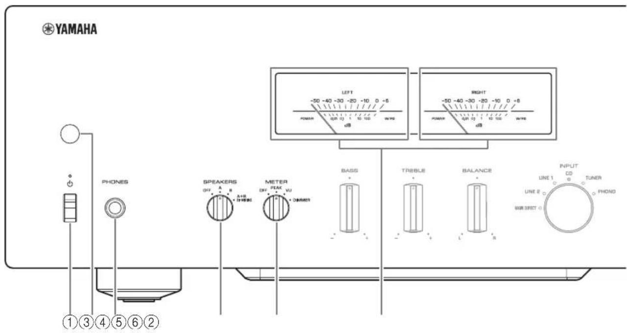
① ⏻ (Power) switch/indicator
| (Power) switch | Power status Indicator | |
| Up position | On Lit brightly | |
| Standby Lit dimly | ||
| Down position Off | Off | |
While the ⏻ (Power) switch is in the up position, press the ⏻ AMP key on the remote control repeatedly to switch the power to the unit between on and standby mode. In addition, under either of the following conditions, the unit will enter standby mode.
- If the Auto Power Standby function is enabled. ( page 10)
- If you turn off the power to a device that has been set to trigger connection to this unit. (→ page 20)
NOTICE
If you plan not to use the unit for an extended period of time, be sure to unplug the power plug from the AC outlet. Even when the power is turned off, a minimal amount of electric current is still flowing to the unit.
Note
- After you turn on the unit, it will take a few seconds before the unit can reproduce sound.
- Do not turn on the power to this unit again within 10 seconds after the power has been turned off. Doing so may generate noise.
- While the unit is in standby mode, to turn on power to the unit first set the ⏻ (Power) switch to the down position to turn the power off, then set the switch to the up position.
- While the unit is in standby mode, if you unplug the power cable from the AC outlet and then plug it in again, the power to the unit will be turned on.
② Remote control sensor
Receives signals from the remote control. (→ page 14)
③PHONES jack
Connect your headphones here.
Note
- Connecting the headphones here will result in the following:
- No sound will be heard from the connected speakers.
- Audio signals will not be output at the PRE OUT jacks.
- You will be unable to select MAIN DIRECT as the input source.
- If MAIN DIRECT is selected as the input source, audio signals will not be output at the PHONES jack.
④SPEAKERS selector
Switches sets of speakers connected to the SPEAKERS L/R CH A and B terminals on the rear panel as follows:
OFF: No audio signals will be output from the speakers.
A: Audio signals will be output from the set of speakers connected to the A terminals.
B: Audio signals will be output from the set of speakers connected to the B terminals.
A+B BI-WIRING: Audio signals will be output from the sets of speakers connected to the A and B terminals. Select this position when you plan to make a bi-wired connection. (→ page 19)
NOTICE
[Model for Asia]
If you connect two sets of speakers (A+B), use the speakers with an impedance of 12Ω or higher.
[Other models]
If you connect two sets of speakers (A+B), use the speakers with an impedance of 8Ω or higher.
⑤METER selector
Switches the meter function as follows:
OFF: Turns off meter operation and display illumination.
PEAK: Switches the meter display type to a peak level meter. The peak level meter shows the highest instantaneous level of an audio output signal.
VU: Switches the meter display type to a VU (Volume Unit) level meter. The VU level meter shows an effective audio output value that represents the way sound is perceived by human ears.
DIMMER: When selected, the DIMMER automatically changes the brightness of the meter display in steps. When you see the brightness level you desire, switch to another setting parameter to lock in the new brightness setting.
⑥Meter (LEFT/RIGHT)
Indicates the audio output level of the left (LEFT) and right (RIGHT) channels.
Part Names and Functions
Front panel
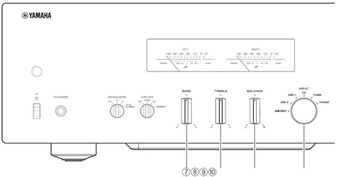
⑦BASS control
Adjusts the volume level of the bass range.
Adjustable range: -10 dB - 0 - +10 dB
⑧TREBLE control
Adjusts the volume level of the treble range.
Adjustable range: -10 dB - 0 - +10 dB
⑨BALANCE control
Adjusts the audio output balance between the left and right speakers to compensate for sound imbalances caused by speaker locations or listening room conditions.
Note
- If both BASS and TREBLE controls are set to 0 (zero), the audio signal will bypass the tone control circuit.
- The BASS, TREBLE, and BALANCE control settings will not affect the input signals at the MAIN IN jacks nor the output signals at the LINE 2 OUT jacks.
⑩ INPUT selector/indicator
Selects the input source. The indicator for the selected input source lights up. Audio signals of the selected input source will be output at the LINE 2 OUT jacks.
MAIN DIRECT: Selects the component connected to the MAIN IN jacks as the input source.
LINE 1/LINE 2: Selects the component connected to the LINE 1 or LINE 2 jacks as the input source.
CD: Selects the CD player connected to the CD input jacks as the input source.
TUNER: Selects the tuner connected to the TUNER input jacks as the input source.
PHONO: Selects the turntable connected to the PHONO input jacks as the input source.
Note
- If MAIN DIRECT is selected as the input source, audio signals will not be output at the PRE OUT, LINE 2 OUT or PHONES jacks.
- If LINE 2 is selected, audio signals will not be output at the LINE 2 OUT jacks.
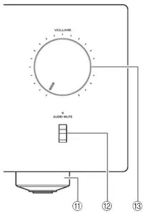
⑪Feet
If the unit is unstable, adjust the height of the feet as needed by rotating them.
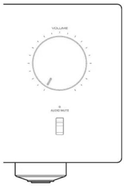
⑫AUDIO MUTE switch/indicator
Press this switch to reduce the current volume level by approximately 20 dB. The indicator will light up. Press again to restore the audio output to the previous volume level. The indicator will turn off.
⑬VOLUME knob
Adjusts the volume level. This setting will not affect the output level at the LINE 2 OUT jacks.
NOTICE
If you select MAIN DIRECT as the input source for this unit, the volume level will be fixed. In this case, to adjust the volume level, use the volume control on the external amplifier connected to the MAIN IN jacks.
Part Names and Functions
Rear panel
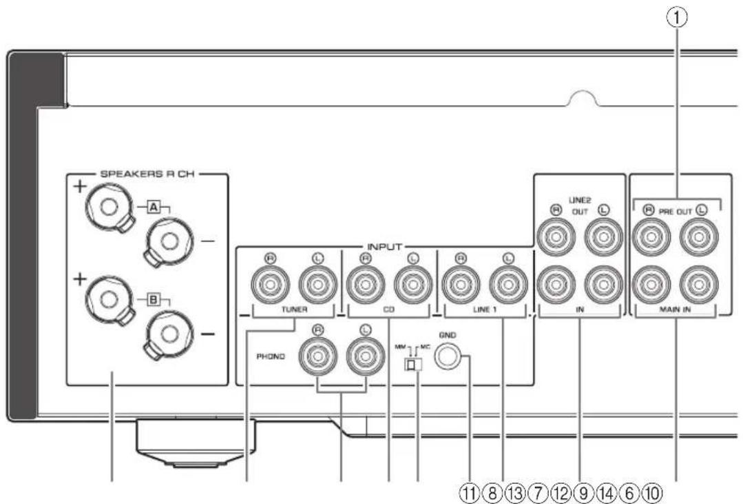
①PRE OUT jacks
Note
- Audio signals output at the PRE OUT jacks are the same channel signals that are output at the SPEAKERS L/R CH terminals.
-
The following parameter settings are effective for audio signals output at the PRE OUT jacks.
-
BASS
- TREBLE
- BALANCE
- VOLUME
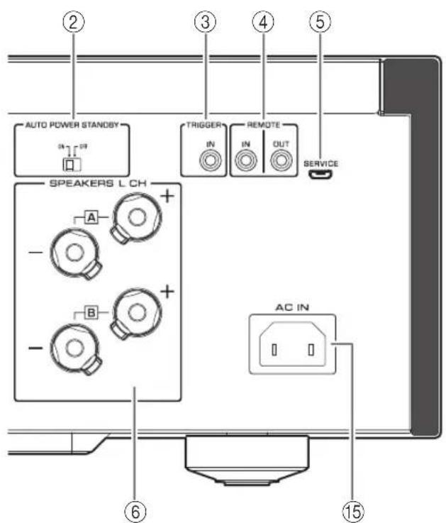
② AUTO POWER STANDBY switch
ON: The unit enters standby mode automatically if it is left turned on and not operated for eight hours (Auto Power Standby function).
OFF: The unit does not enter standby mode automatically.
③TRIGGER IN jack
Connect external components that support the trigger function. (→page 20)
④REMOTE IN/OUT jacks
Connect external components that support the remote function. (→pages 20 and 21)
⑤SERVICE jack
This jack is used to test the product.
⑥SPEAKERS L/R CH terminals
⑦TUNER input jacks
⑧PHONO input jacks
⑨CD input jacks
⑩MM/MC switch
Set this switch to the MM or MC position according to the type of magnetic cartridge installed in the turntable that is connected to the PHONO input jacks.
Note
Before you replace the cartridge for the turntable, be sure to turn off the power to this unit.
⑪GND (Ground) terminal
If you connect your turntable to this unit, ground it to the GND terminal. Doing so may reduce noise.

CAUTION
Do not loosen the GND terminal knob excessively. Otherwise, the knob may come off and a child may swallow it accidentally.
Note
This is not a safety ground.
⑫LINE 1 input jacks
⑬LINE 2 jacks
Connect external components that feature analog audio in/out jacks.
⑭MAIN IN jacks
Connect external components that feature a volume control function so that you can use this unit as a power amplifier.
NOTICE
If you select MAIN DIRECT as the input source for this unit, the volume level will be fixed. In this case, to adjust the volume level, use the volume control on the external amplifier connected to the MAIN IN jacks.
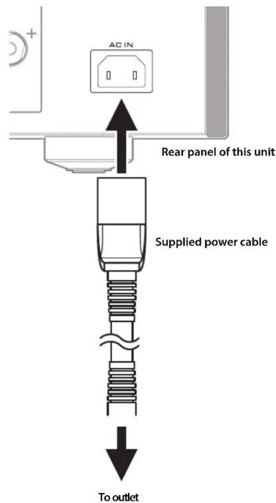
⑮AC IN jack
Connect the supplied power cable here. ( page 21)
Part Names and Functions
Remote control
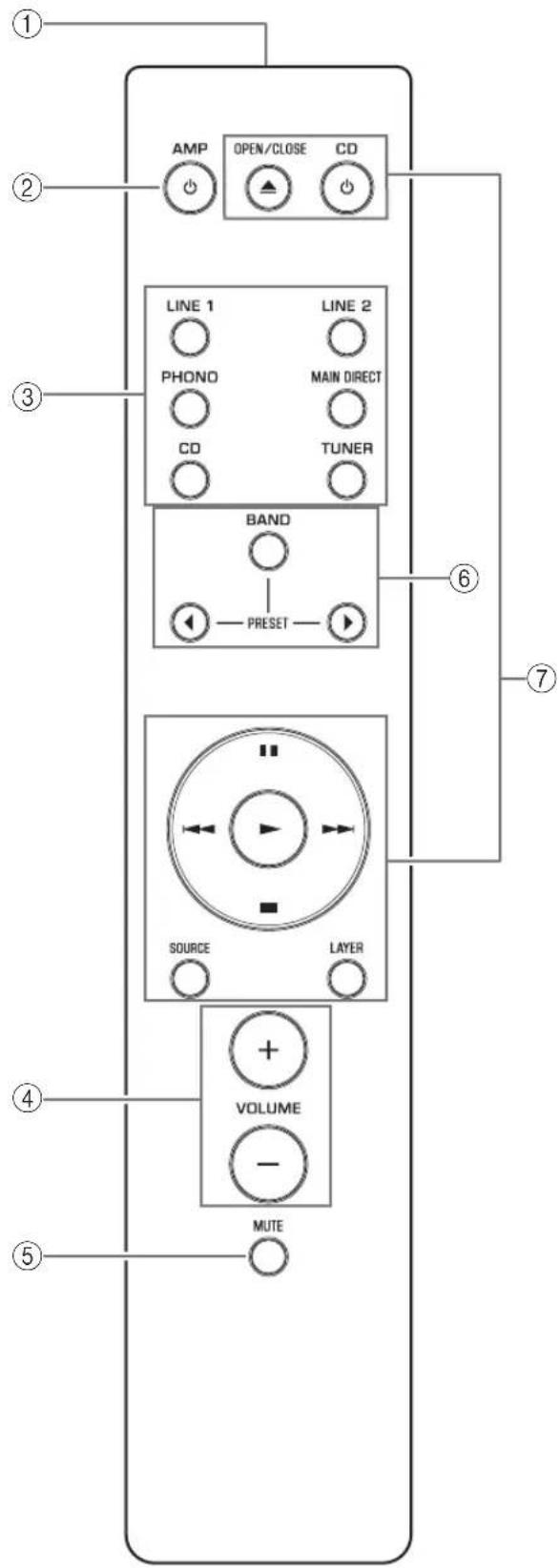
①Infrared signal transmitter
Outputs infrared control signals toward the unit. (→page 14)
② AMP key
Turns on the power to the unit or switches it to standby mode. (→page 6)
③Input select keys
Select the input source.
Audio signals of the selected input source will be output at the LINE 2 OUT jacks.
LINE 1/LINE 2: Selects the component connected to the LINE 1 or LINE 2 jacks as the input source.
PHONO: Selects the turntable connected to the PHONO input jacks as the input source.
MAIN DIRECT: Selects the component connected to the MAIN IN jacks as the input source.
CD: Selects the CD player connected to the CD input jacks as the input source.
TUNER: Selects the tuner connected to the TUNER input jacks as the input source.
Note
- If MAIN DIRECT is selected as the input source, audio signals will not be output at the PRE OUT, LINE 2 OUT or PHONES jacks.
- If LINE 2 is selected, audio signals will not be output at the LINE 2 OUT jacks.
④VOLUME +/- keys
Adjust the volume level. This setting will not affect the output level at the LINE 2 OUT jacks.
NOTICE
If you select MAIN DIRECT as the input source for this unit, the volume level will be fixed. In this case, to adjust the volume level, use the volume control on the external amplifier connected to the MAIN IN jacks.
⑤MUTE key
Press this key to reduce the current volume level by approximately 20 dB. Press the key again to restore the previous volume level.
⑥Tuner control keys
Control the functions of a connected Yamaha tuner. For more information, refer to the owner's manual for your tuner.
⑦CD player control keys
Control the functions of a connected Yamaha CD player. For more information, refer to the owner's manual for your CD player.
OPEN/CLOSE key: Opens or closes the disc tray of a connected CD player.
CD key: Turns on the power to a connected CD player, or switches it to standby mode.
▶ (Play): Starts playback of the CD player.
■ (Pause): Pauses playback of the CD player.
Press ▶ or to resume playback.
■ (Stop): Stops playback of the CD player.
/ (Skip): Skips to the next track, or returns to the beginning of the current track.
SOURCE key: Selects the source to be played on the CD player. The playback source changes each time this key is pressed.
LAYER key: Toggles the playback layer of a hybrid super audio CD between “Super audio CD” and “CD.”
Note
Some Yamaha tuners or CD players might not support the tuner or CD player control keys.
Part Names and Functions
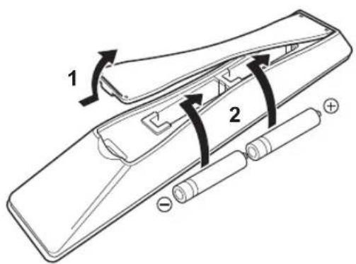
■Installing batteries in the remote control
1 Remove the battery compartment cover.
2 Insert two batteries (AAA, R03, UM-4) according to the polarity markings (+ and −) on the inside of the battery compartment.
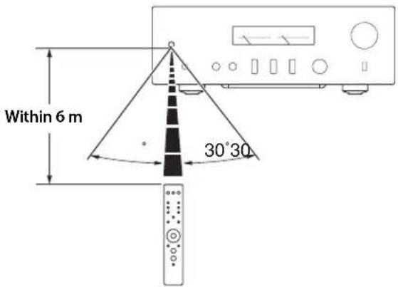
■Operating the remote control
Operate the remote control in the range shown below by pointing it toward the remote control sensor on the front panel of the unit.
3Reinstall the battery compartment cover.

natural_image
Line drawing of a mechanical component with a numbered arrow indicating rotation (no text or symbols present)Connections
This section explains how to connect the unit to speakers and audio source components.
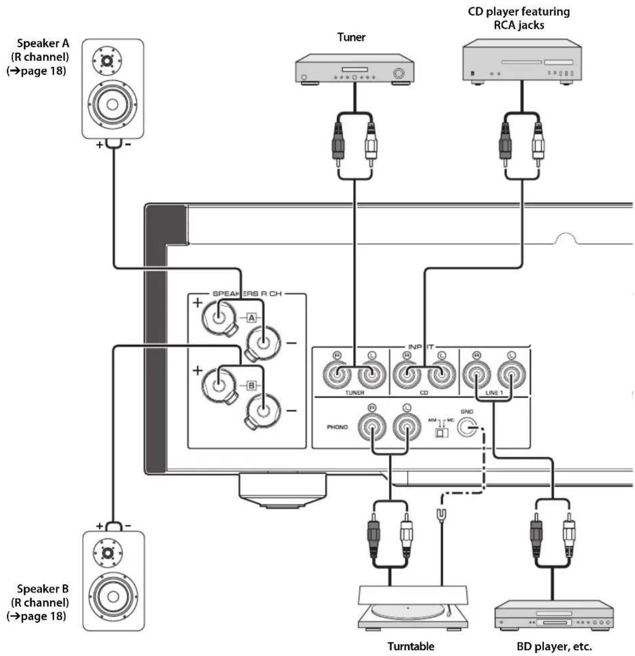
Connections
Connection diagram

CAUTION
Be sure to complete all connections before plugging in the power cable to an AC outlet. (→ page 21)
flowchart
graph TD
    A["Speaker A (R channel) (→page 18)"] -->|+ -| B["Tuner"]
    C["Speaker B (R channel) (→page 18)"] -->|+ -| D["CD player featuring RCA jacks"]
    B --> E["TURNTABLE"]
    D --> F["BD player, etc."]
    E --> G["PhONO"]
    F --> H["INPUT"]
    G --> I["TRANSPORTER"]
    H --> J["CD"]
    I --> K["LINE 1"]
NOTICE
If a component is connected to the MAIN IN jacks, the unit's volume level will be fixed. Therefore, do not connect a CD player or other components that do not feature volume adjustment to the MAIN IN jacks. Otherwise, a loud sound may be emitted, resulting in malfunction of the unit or damage to the speakers.
flowchart
graph TD
    A["External amplifier or active subwoofer"] --> B["Speaker A (L channel)"]
    A --> C["Speaker B (L channel)"]
    B --> D["Speaker A"]
    B --> E["Speaker B"]
    C --> F["Speaker A"]
    C --> G["Speaker B"]
    D --> H["Line2 OUT L"]
    D --> I["PRI OUT L"]
    D --> J["MAIN IN"]
    E --> K["SPEAKE 3 L CH"]
    E --> L["TRIGGER IN"]
    E --> M["REMOTE OUT SERVICE"]
    F --> N["AC IN"]
    G --> O["CD recorder, tape deck, etc."]
    G --> P["Preamplifier, AV amplifier, etc."]
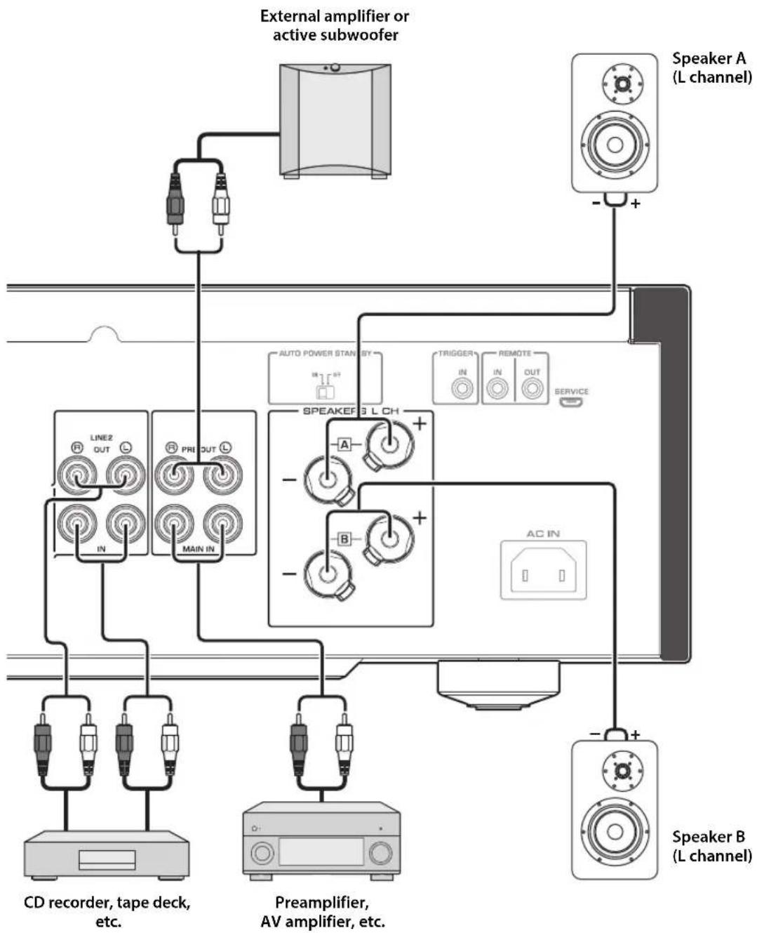
Connections
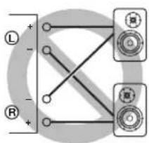
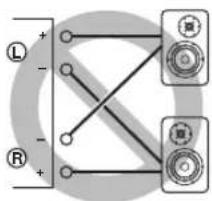
Note
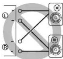
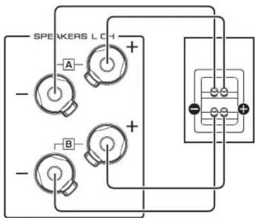
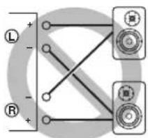
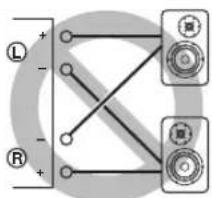
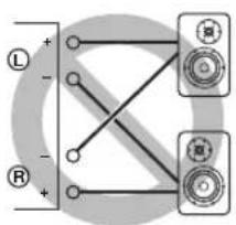
- Because this power amplifier is of the floating balanced type, the following connections are not possible.
- Connecting between two "+" (or two "-" terminals of the left and right channels (Fig. 1).
- Connecting each “—” terminal of the unit's left and right channels to the opposite channel speakers (cross connection, Fig. 2).
- Connecting the left/right channel “—” terminals (or accidentally allowing them to come in contact) with the metal part of the rear panel of this unit.
Figure 1
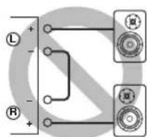
Figure 2
- Do not connect an active subwoofer to the SPEAKERS L/R CH terminals. Connect the subwoofer to the unit's PRE OUT jacks.
Connecting speakers
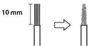
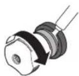
■Using speaker cables
1 Remove approximately 10 mm of insulation from the end of each speaker cable, and twist the exposed wires together tightly to prevent short circuits.
2Unscrew the knob on each speaker terminal, and then insert the bare wire into the side hole on the terminal.
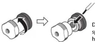
Diameter of the speaker cable wire hole: 6.0 mm
3Tighten the knob.

CAUTION
- Do not loosen the knob excessively. Otherwise, the knob may come off and a child may swallow it accidentally.
• To reduce the risk of electric shock, do not touch the speaker terminals while the power to the unit on.
NOTICE
- If the SPEAKERS terminals come into contact with a metallic rack, a short circuit may occur, resulting in damage to this unit. When installing the unit in a rack, maintain a sufficient clearance to prevent the SPEAKERS terminals from coming into contact with the rack.
- Do not let the bare speaker wires touch each other, nor let them touch any metal part of this unit. Otherwise, the unit and/or the speakers may be damaged.
Note
All connections must be correct: L (left) to L, R (right) to R, "+" to "+" and "-" to "-" . For information regarding the connection procedure, refer to the owner's manual for your speakers.
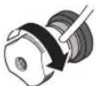
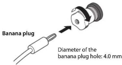
■Using banana plug cables
(Models for U.S.A., Canada, Australia, China, and Taiwan)
First tighten the knob on the SPEAKERS terminal, and then insert the banana plug into the head of the knob.
■Using Y-shaped lug cables
1Unscrew the knob, and then sandwich the Y-shaped lug between the ring part and base of the terminal.
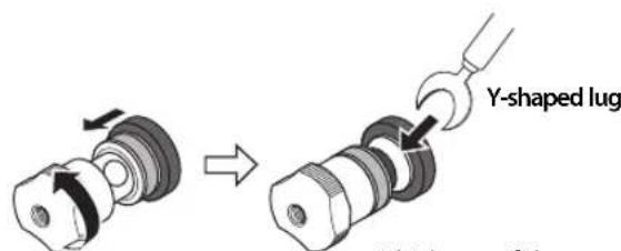
Thickness of the terminal core: 5.8 mm
2Tighten the knob.
Bi-wired connection
A bi-wired connection separates the woofer from the mid and high ranges. Speakers that support bi-wired connection feature two pairs of terminals (total four terminals). These two pairs of terminals can divide the speakers into two independent parts. To make this kind of connection, you need to connect mid and high range drivers to one pair of terminals, and low range drivers to the other pair of terminals.
1 Remove the shorting bars or bridges on the speakers.
2Connect this unit to the speakers as shown in the figure below.
An example of left channel connection
Rear panel of this unit Speaker
3Set the SPEAKERS selector on the front panel to A+B BI-WIRING.
Connections
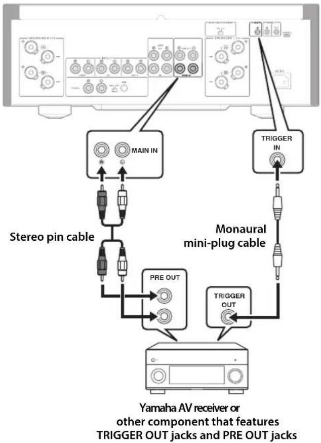
Trigger connection
You can connect a Yamaha AV receiver or other component that supports the Trigger function. You can control this unit in sync with a connected component.
Rear panel of this unit
flowchart
graph TD
    A["Main IN"] --> B["Stereo pin cable"]
    A --> C["MONAURAL MINI-PLUG CABLE"]
    A --> D["Yamaha AV receiver or other component that features TRIGGER OUT jacks and PRE OUT jacks"]
    C --> E["PRE OUT"]
    C --> F["TRIGGER OUT"]
    G["TRIGGER IN"] --> A
When the power to the connected component is turned on, the power to this unit is also turned on. Simultaneously, the input source to the unit is set to MAIN DIRECT. If MAIN DIRECT has been selected as the input source for this unit, when the power to the connected component is turned off, this unit will enter standby mode.
Note
When the power switch on this unit is turned Off, the power to the unit will not be triggered.
Remote connection
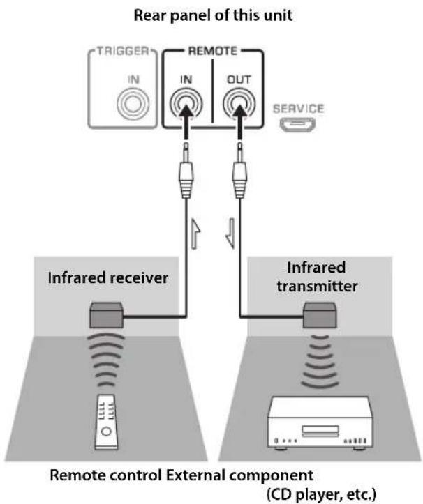
■Operating the unit from another room
If you connect a commercially-available infrared receiver and transmitter to the unit's REMOTE IN/OUT jacks, you will be able to operate the unit and/or external component from another room, using the supplied remote control.
flowchart
graph TD
    A["TRIGGER"] --> B["IN"]
    B --> C["REMOTE"]
    C --> D["OUT"]
    D --> E["SERVICE"]
    F["Infrared receiver"] --> G["Remote control External component (CD player, etc.)"]
    H["Infrared transmitter"] --> I["Remote control External component (CD player, etc.)"]
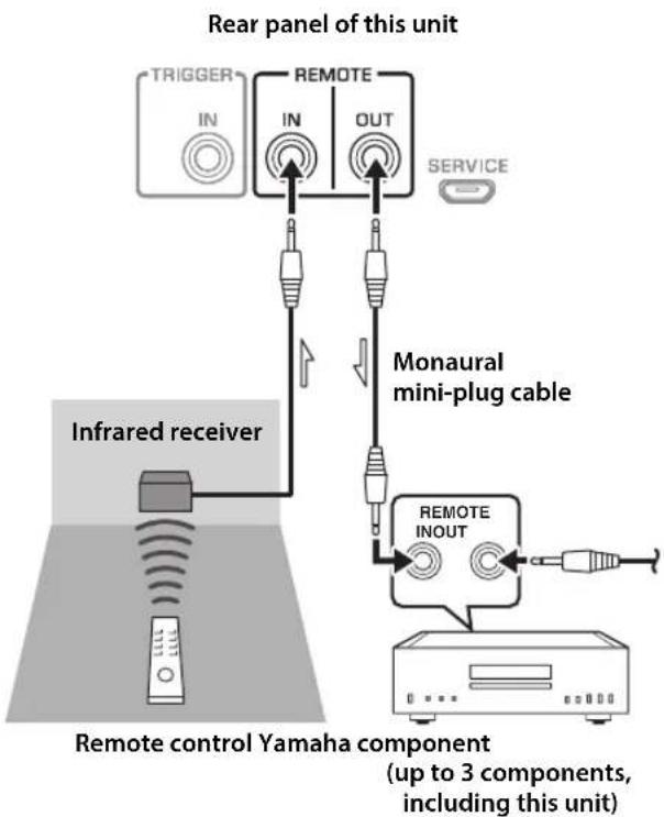
■Remote connection between Yamaha components
If you have another Yamaha component that supports remote connections, an infrared transmitter is not necessary. Connect an infrared receiver to the unit's REMOTE IN/OUT jacks, as shown below.
Up to 3 Yamaha components (including this unit) can be set up for remote connection.
flowchart
graph TD
    A["TRIGGER"] --> B["IN"]
    B --> C["IN"]
    C --> D["OUT"]
    D --> E["Service"]
    F["Infrared receiver"] --> G["Inverter"]
    H["Remote control Yamaha component (up to 3 components, including this unit)"] --> I["REMOTE INOUT"]
    I --> J["Monaural mini-plug cable"]
Connecting the power cable
After all connections are complete, plug the power cable into the AC IN connector of the unit, and then plug the power plug into the AC outlet.
Appendix
This section lists technical specifications for this unit.
Appendix
Specifications
Rated output power (20 Hz to 20 kHz, 0.07% THD)
2-channel driven
[Model for Asia]
8Ω....90 W + 90 W
6Ω....110 W + 110 W
[Other models]
8Ω....90 W + 90 W
4 150W+150W
Dynamic power
8Ω.... 105 W + 105 W
6Ω....135 W + 135 W
4Ω.... 190 W + 190 W
2Ω 220 W + 220 W
IEC output power (1 kHz, 0.07% THD)
[Models for U.K. and Europe]
8Ω....95 W + 95 W
Maximum effective output power
(JEITA, 1 kHz, 10% THD)
8Ω.... 120 W + 120 W
4Ω 190 W + 190 W
Power bandwidth (0.1% THD, 45 W)
2-channel driven
8Ω....10 Hz to 50 kHz
Damping factor (1 kHz)
8Ω....250 or higher
Input sensitivity / input impedance (1 kHz, 100 W/8Ω)
PHONO (MC) 150 μVrms / 50Ω
PHONO (MM) 3.5 mVrms / 47 kΩ
CD (or similar) 200 mVrms / 47 kΩ
MAIN IN ....1 Vrms / 47 kΩ
Maximum input / signal voltage (1 kHz, 0.5% THD)
PHONO (MC).... 2.0 mVrms
PHONO (MM).... 50 mVrms
CD (or similar).... 2.80 Vrms
Rated output voltage / output impedance
LINE 2 OUT.... 200 mVrms / 1.5 kΩ
PRE OUT.... 1 Vrms / 1.5 kΩ
Headphone jack rated output power
(1 kHz, 32Ω, 0.2% THD)
25 mW + 25 mW
Frequency response
5 Hz to 100 kHz....+0 / -3 dB
20 Hz to 20 kHz....+0 / -0.3 dB
Deviations from RIAA equalizer
PHONO (MM/MC) ....±0.5 dB
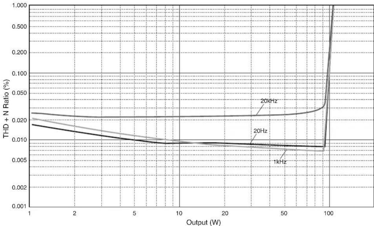
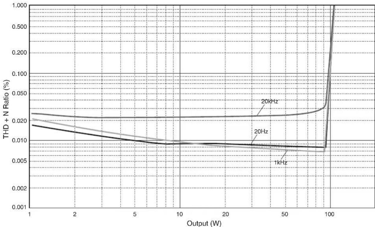
Total harmonic distortion plus noise
(JEITA, input 0.5 V, 20 Hz to 20 kHz)
2-channel driven
PHONO (MC) → LINE 2 OUT, 1.2 Vrms.....0.02%
PHONO (MM) → LINE 2 OUT, 1.2 Vrms .....0.005%
CD (or similar) → SPEAKERS OUT, 50 W/8Ω
0.035%
Signal-to-noise ratio (JEITA, IHF-A network)
PHONO (MC)....90 dB
PHONO (MM).... 96 dB
CD (or similar).... 110 dB
Residual noise (IHF-A network)
50 μVrms
Channel separation (JEITA, 1 kHz/10 kHz)
PHONO (MC)....66/77 dB or higher PHONO (MM)....90/77 dB or higher CD (or similar)....74/54 dB or higher
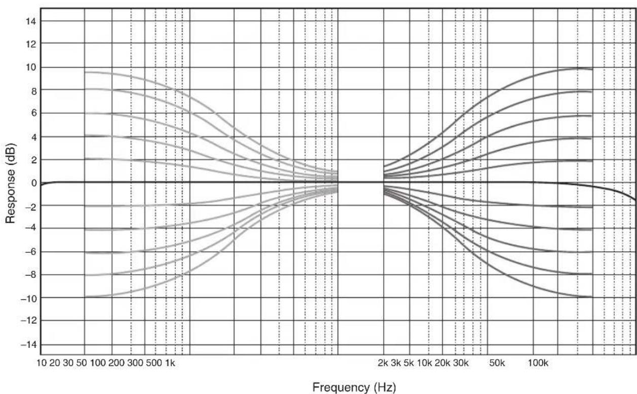
Tone control characteristics
BASS
Boost/cut 50 Hz / ±9 dB
Turnover frequency.... 350 Hz
TREBLE
Boost/cut 20 kHz / ±9 dB
Turnover frequency.... 3.5 kHz
Power supply
[Models for U.S.A. and Canada] ..... AC 120 V, 60 Hz
[Model for China]...... AC 220 V, 50 Hz
[Model for Korea]...... AC 220 V, 60 Hz
[Model for Australia]...... AC 240 V, 50 Hz
[Models for U.K. and Europe]...... AC 230 V, 50 Hz
[Model for Asia] ......AC 220–240 V, 50 Hz/60 Hz
[Model for Taiwan]......AC 110 V, 60 Hz
Power consumption
[Model for Asia] 250 W
[Other models].... 350 W
Standby power consumption
OFF mode 0.1 W
Standby mode 0.2 W
Maximum power consumption (1 kHz, 4Ω 10% THD)
[Model for Taiwan].... 700 W
Dimensions (W × H × D)
435× 157× 463mm
Weight
22.0 kg
* The contents of this manual apply to the latest specifications as of the publishing date. To obtain the latest manual, access the Yamaha website and download the manual file.
Block diagram
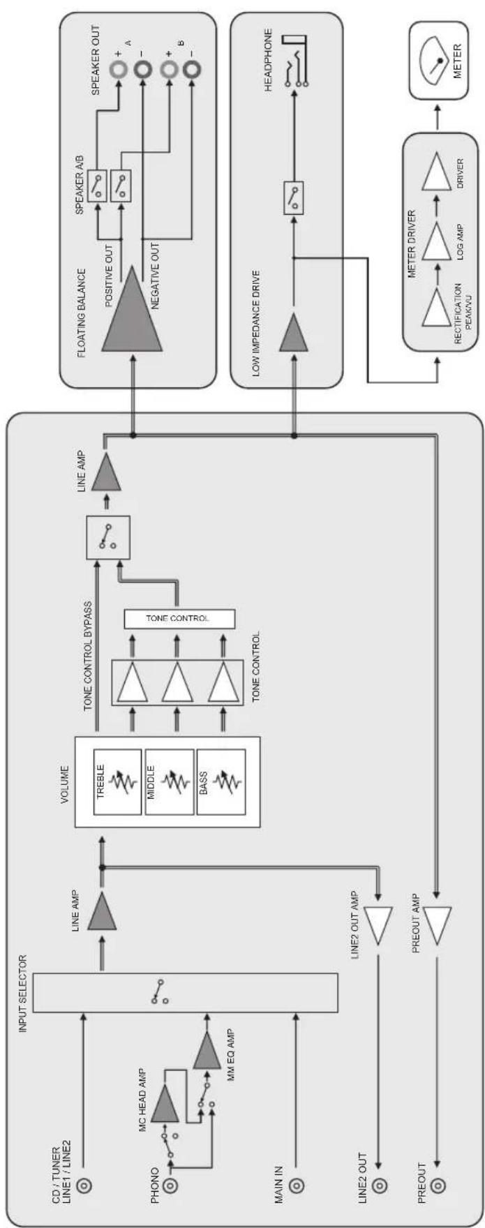
flowchart
graph TD
    A["CD / TUNER\nLINE1 / LINE2"] --> B["INPUT SELECTOR"]
    C["PHONO"] --> D["MC HEAD AMP"]
    D --> E["MM EQ AMP"]
    F["MAIN IN"] --> G["LINE2 OUT"]
    H["PREOUT"] --> I["PREOUT AMP"]
    J["LINE2 OUT"] --> K["TONE OUT AMP"]
    L["VOLUME"] --> M["TONE CONTROL BYPASS"]
    M --> N["TONE CONTROL"]
    N --> O["LINE AMP"]
    P["FLOATING BALANCE"] --> Q["POSITIVE OUT"]
    Q --> R["SPEAKER A/B"]
    R --> S["SPEAKER OUT"]
    T["LOW IMPEDANCE DRIVE"] --> U["RECTION PERIOD"]
    U --> V["LOG AMP"]
    V --> W["DRIVER"]
    X["METER DRIVER"] --> Y["METER"]
    Y --> Z["Ground"]
    style A fill:#f9f,stroke:#333
    style C fill:#f9f,stroke:#333
    style F fill:#f9f,stroke:#333
    style H fill:#f9f,stroke:#333
    style J fill:#f9f,stroke:#333
    style L fill:#f9f,stroke:#333
    style P fill:#f9f,stroke:#333
    style Q fill:#ccc,stroke:#333
    style R fill:#ccc,stroke:#333
    style S fill:#ccc,stroke:#333
    style T fill:#ccc,stroke:#333
    style U fill:#ccc,stroke:#333
    style V fill:#ccc,stroke:#333
    style W fill:#ccc,stroke:#333
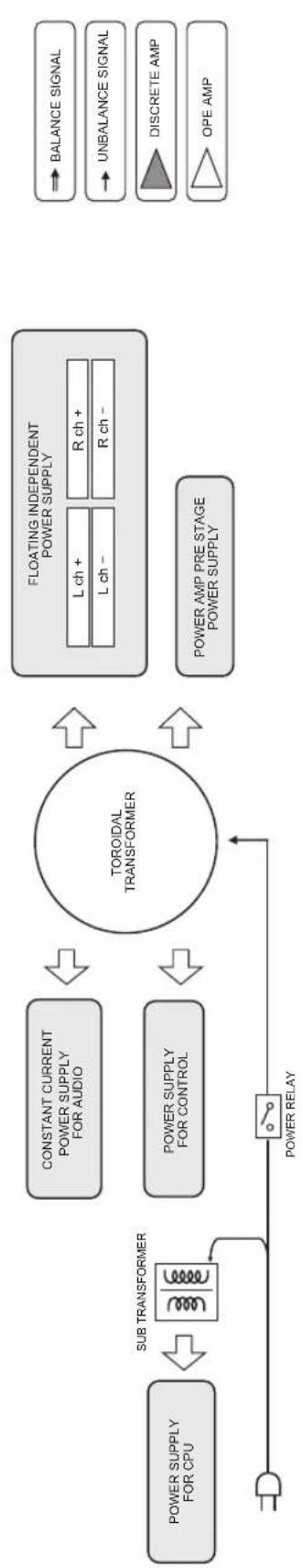
flowchart
graph TD
    A["POWER SUPPLY FOR CPU"] --> B["SUB TRANSFORMER"]
    B --> C["TOROIDAL TRANSFORMER"]
    C --> D["FLOATING INDEPENDENT POWER SUPPLY"]
    D --> E["BALANCE SIGNAL"]
    D --> F["UNBALANCE SIGNAL"]
    D --> G["DISCRETE AMP"]
    D --> H["OPE AMP"]
    C --> I["POWER SUPPLY FOR CONTROL"]
    I --> J["POWER RELAY"]
    J --> C
    C --> K["L ch + R ch + L ch - R ch -"]
Acoustic characteristics
■Tone control characteristics
line
| Frequency (Hz) | Response (dB) | | -------------- | ------------- | | 10 | 0 | | 20 | 0 | | 30 | 0 | | 50 | 0 | | 100 | 0 | | 200 | 0 | | 300 | 0 | | 500 | 0 | | 1k | 0 | | 2k | 0 | | 3k | 0 | | 5k | 0 | | 10k | 0 | | 20k | 0 | | 30k | 0 | | 50k | 0 | | 100k | 0 |■Total harmonic distortion
line
| Output (W) | 1kHz | 20Hz | 20kHz | | ---------- | ------- | ------- | ------- | | 1 | 0.018 | 0.021 | 0.022 | | 5 | 0.010 | 0.012 | 0.013 | | 10 | 0.009 | 0.010 | 0.011 | | 20 | 0.008 | 0.009 | 0.010 | | 50 | 0.007 | 0.008 | 0.009 | | 100 | 0.007 | 0.007 | 0.008 |Appendix
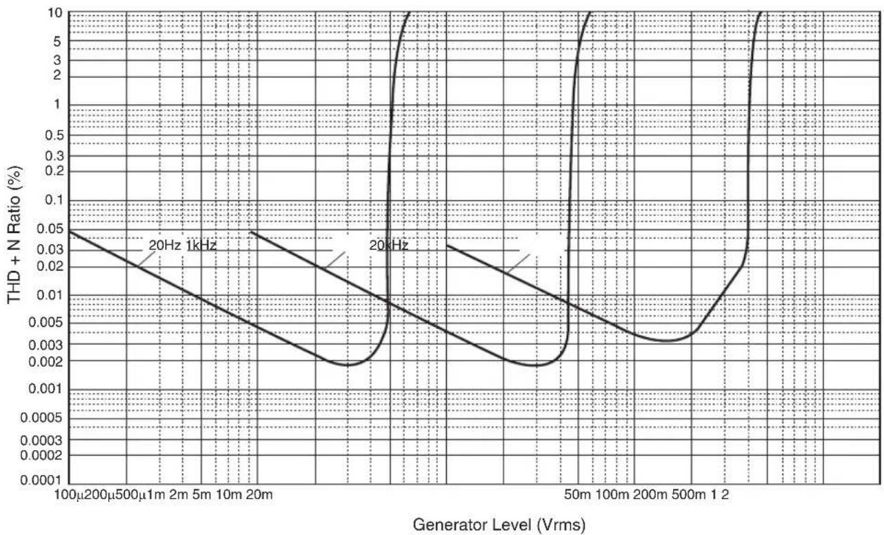
■Total harmonic distortion (PHONO)

line
| Generator Level (Vrms) | 20Hz THD + N Ratio (%) | 1kHz THD + N Ratio (%) | | ---------------------- | ---------------------- | ---------------------- | | 100μ | 0.05 | 0.05 | | 200μ | 0.03 | 0.03 | | 500μ | 0.02 | 0.02 | | 1m | 0.01 | 0.01 | | 2m | 0.005 | 0.005 | | 5m | 0.003 | 0.003 | | 10m | 0.002 | 0.002 | | 20m | 0.001 | 0.001 | | 50m | 10.0 | 10.0 | | 100m | 1.0 | 1.0 | | 200m | 0.1 | 0.1 | | 500m | 0.01 | 0.01 | | 12 | 1.0 | 1.0 |Troubleshooting
Refer to the table below if this unit does not function properly. If the instructions below do not help, or if the problem you are experiencing is not listed below, turn off the unit, disconnect the power plug, and contact the nearest authorized Yamaha dealer or service center.
| Problem Cause Remedy | See page | ||
| Power does not turn on. | The power cable is not connected to the AC IN connector on the rear panel or is not plugged into an AC outlet. | Connect the power cable firmly. 21 | |
| The unit has been exposed to a strong external electric shock (such as lightning or strong static electricity). | Turn off the unit, disconnect the power plug from the AC outlet, wait for about 30 seconds, and then plug the unit in again. | — | |
| The ⏻ (Power) indicator on the front panel flashes. | The protection circuitry has been activated because of a short circuit, etc. | Make sure that the speaker wires are not touching each other or shorting out against the rear panel of the unit, and then turn on the power to the unit. | 18 |
| There is a problem with the internal circuitries of this unit. | Disconnect the power plug from the AC outlet and contact the nearest authorized Yamaha dealer or service. | — | |
| When the unit is powered on, the INPUT indicator flashes and the volume level decreases. | The protection circuitry has been activated because of a short circuit, etc. | Make sure that the speaker wires are not touching each other or shorting out against the rear panel of the unit, and then turn on the power to the unit. | 18 |
| No sound is heard. | Incorrect input or output cable connections. | Connect the cables properly. If the problem persists, the cables might be defective. | 16 |
| No appropriate input source has been selected. | Select an appropriate input source using the INPUT selector on the front panel (or one of the input selector keys on the remote control). | 8, 12 | |
| The SPEAKERS selector is set to OFF. | Set the SPEAKERS selector to the appropriate position. | 7 | |
| The speaker cables are not connected properly. | Make sure that the speaker cables are connected properly. | 18 | |
| The sound is suddenly muted. | The protection circuitry has been activated because of a short circuit, etc. | Make sure that the speaker wires are not touching each other or shorting out against the rear panel of the unit, and then turn on the power to the unit. | 18 |
| The volume level cannot be adjusted. | MAIN DIRECT is selected as the input source. | Adjust the volume level on the connected component.Alternatively, connect the external component to a pair of the input jacks other than the MAIN IN jacks, and then select the corresponding input source. | 8 |
| Only one channel speaker can be heard. | The playback component or speakers are not connected properly. | Make sure that they are connected properly. If the problem persists, the cables might be defective. | 16 |
| The volume level balance between the left and right speakers is not adjusted properly. | Adjust the volume level balance between the left and right speakers properly using the BALANCE control. | 8 | |
Appendix
| Problem Cause Remedy | See page | ||
| There is a lack of bass and no ambience. | The + and - wires are connected in reverse at the amplifier or the speakers. | Connect the speaker wires to the correct + and - phase. | 18 |
| A “humming” noise is heard. | Incorrect input or output cable connections. | Connect the cables properly. If the problem persists, the cables might be defective. | 16 |
| The turntable is not grounded to the GND terminal. | Connect the turntable to the GND terminal of this unit. | 16 | |
| Playback audio is distorted while you listen to a connected CD player or tape deck through headphones (that are connected to a CD player or tape deck). | The power to the unit is turned off. Turn on the power to the unit. 6 | ||
| The volume level of the vinyl record is too low. | The MM/MC switch on the rear panel is set incorrectly. | Set the MM/MC switch to the MM or MC position according to the type of magnetic cartridge of the turntable. | 10 |
| The remote control does not work or function properly. | The remote control has been used out of the operating range. | The remote control must be used within a maximum distance of 6 m and no more than 30 degrees off-axis from the remote control sensor on the front panel. | 14 |
| Direct sunlight or lighting (from an inverter type of fluorescent lamp, strobe light, etc.) is hitting the remote control sensor on the front panel. | Change the orientation of the lighting or reposition the unit. | — | |
| The batteries are weak. Replace all batteries. 14 | |||
Maintenance
Mirror-finish side panels
We recommend that you use a cleaning cloth such as those made for pianos.
Other surfaces
Do not use chemical agents, such as benzene or thinner for cleaning. Otherwise, the surfaces might be damaged. Wipe the surfaces using a soft dry cloth.
Note
④Prises REMOTE IN/OUT
natural_image
Line drawing of a mechanical component with a numbered arrow indicating direction (no text or symbols present)Figure 2

MAIN IN ....1 Vrms / 47 kΩ
PHONO (MC).... 2,0 mVrms
PHONO (MM).... 50 mVrms
Accentuation/atténuation 50 Hz / ± 9 dB
Accentuation/atténuation 20 kHz / ±9 dB
Dimensions (L × H × P)
435 × 157 × 463 mm
Poids
22,0 kg
Hinweis
④Buchsen REMOTE IN/OUT
natural_image
Line drawing of a mechanical component with a numbered arrow indicating direction (no text or symbols present)Abb. 2
(JEITA, 1 kHz, 10% THD)
8Ω.... 120 W + 120 W
4Ω.... 190 W + 190 W
MAIN IN ....1 Vrms / 47 kΩ
PHONO (MC).... 2,0 mVrms
PHONO (MM).... 50 mVrms
CD (o.Ä.) 2,80 Vrms
Total harmonisk distorsion .....111
Total harmonisk distorsion (PHONO).....112
Felsökning....113
Underhåll....114
②Fjärrkontrollsensor
⑪Fötter
④REMOTE IN/OUT-uttag
natural_image
Line drawing of a mechanical component with a numbered arrow indicating direction (no text or symbols present)Anslutningar
Figur 2
MAIN IN ....1 Vrms / 47 kΩ
PHONO (MC).... 2,0 mVrms
PHONO (MM).... 50 mVrms
CD (eller liknande) 2,80 Vrms
line
| Frequency (Hz) | Response (dB) | | -------------- | ------------- | | 10 | 0 | | 20 | 0 | | 30 | 0 | | 50 | 0 | | 100 | 0 | | 200 | 0 | | 300 | 0 | | 500 | 0 | | 1k | 0 | | 2k | 0 | | 3k | 0 | | 5k | 0 | | 10k | 0 | | 20k | 0 | | 30k | 0 | | 50k | 0 | | 100k | 0 |■Total harmonisk distorsion
line
| Output (W) | 1kHz | 20Hz | 20kHz | | ---------- | ------- | ------- | ------- | | 1 | 0.018 | 0.021 | 0.022 | | 5 | 0.010 | 0.012 | 0.013 | | 10 | 0.009 | 0.010 | 0.011 | | 20 | 0.008 | 0.009 | 0.010 | | 50 | 0.007 | 0.008 | 0.009 | | 100 | 0.007 | 0.007 | 0.008 |■Total harmonisk distorsion (PHONO)
line
| Generator Level (Vrms) | 20Hz THD + N Ratio (%) | 1kHz THD + N Ratio (%) | | ---------------------- | ---------------------- | ---------------------- | | 100μ | 0.05 | 0.05 | | 200μ | 0.03 | 0.03 | | 500μ | 0.02 | 0.02 | | 1m | 0.01 | 0.01 | | 2m | 0.005 | 0.005 | | 5m | 0.003 | 0.003 | | 10m | 0.002 | 0.002 | | 20m | 0.001 | 0.001 | | 50m | 10.0 | 10.0 | | 100m | 1.0 | 1.0 | | 200m | 0.1 | 0.1 | | 500m | 0.01 | 0.01 | | 12 | 1.0 | 1.0 |Felsökning
Nota
④Prese REMOTE IN/OUT
natural_image
Line drawing of a mechanical component with a numbered arrow indicating direction (no text or symbols present)Figura 2
Collegamento bi-wire
MAIN IN ....1 Vrms / 47 kΩ
PHONO (MC).... 2,0 mVrms
PHONO (MM).... 50 mVrms
CD (o simile) 2,80 Vrms
Rumore residuo (rete IHF-A)
50 μVrms
Consumo energetico in standby
Dimensioni (L × A × P)
435× 157× 463mm
Peso
22,0 kg
Nota
natural_image
Line drawing of a mechanical component with a numbered arrow indicating rotation (no text or symbols present)Figura 2
(JEITA, 1 kHz, 10% THD)
8Ω.... 120 W + 120 W
4Ω.... 190 W + 190 W
MAIN IN ....1 Vrms / 47 kΩ
PHONO (MC).... 2,0 mVrms
PHONO (MM).... 50 mVrms
CD (o similar).... 2,80 Vrms
Opmerking
natural_image
Line drawing of a mechanical component with a numbered arrow indicating rotation (no text or symbols present)Aansluitingen
Afb. 2
MAIN IN ....1 Vrms / 47 kΩ
Maximum ingangs/signaalvoltage (1 kHz, 0,5% THD)
PHONO (MC).... 2,0 mVrms
PHONO (MM).... 50 mVrms
PHONO (MC).... 90 dB
PHONO (MM).... 96 dB
Примечание
natural_image
Line drawing of a mechanical component with a numbered arrow indicating rotation (no text or symbols present)Рис. 2

line
| Frequency (Hz) | Response (dB) | | -------------- | ------------- | | 10 | 0 | | 20 | -10 | | 30 | -8 | | 50 | -6 | | 100 | -4 | | 200 | -2 | | 300 | 0 | | 500 | 2 | | 1k | 4 | | 2k | 6 | | 3k | 8 | | 5k | 10 | | 10k | 12 | | 20k | 14 | | 30k | 12 | | 50k | 10 | | 100k | 8 | | 2k | 6 | | 3k | 4 | | 5k | 2 | | 10k | 0 | | 2k | -2 | | 3k | -4 | | 5k | -6 | | 10k | -8 | | 2k | -10 | | 3k | -8 | | 5k | -6 | | 10k | -4 | | 2k | -2 | | 3k | 0 | | 5k | 2 | | 10k | 4 | | 2k | 6 | | 3k | 8 | | 5k | 10 | | 10k | 12 | | 2k | 14 | | 3k | 12 | | 5k | 10 | | 10k | 8 | | 2k | 6 | | 3k | 4 | | 5k | 2 | | 10k | 0 | | 2k | -2 | | 3k | -4 | | 5k | -6 | | 10k | -8 | | 2k | -10 | | | |https://download.yamaha.com/


