XF200mmF2 R LM OIS WR - Camera FUJIFILM - Free user manual and instructions
Find the device manual for free XF200mmF2 R LM OIS WR FUJIFILM in PDF.
| Product Type | Prime Telephoto Lens |
| Brand | FUJIFILM |
| Model | XF200mmF2 R LM OIS WR |
| Mount | FUJIFILM X Mount |
| Focal Length | 200 mm (35 mm equivalent: 305 mm) |
| Maximum Aperture | f/2 |
| Minimum Aperture | f/22 |
| Optical Construction | 19 elements in 14 groups (including 2 ED and 1 Super ED) |
| Angle of View | 8.1° |
| Image Stabilization | Yes (O.I.S.) |
| Minimum Focus Distance | 1.8 m |
| Maximum Magnification | 0.12× |
| Filter Diameter | 105 mm |
| Dimensions (Diameter × Length) | 122 × 205.5 mm |
| Weight | 2265 g (without caps and hood) |
| Power | Powered by camera |
| Lens Hood | Included (with lock) |
| Compatible Teleconverter | XF1.4X TC F2 WR (sold separately) |
| Weather Sealing | Yes (dust and splash resistant seals) |
| Maintenance and Cleaning | Use a blower for dust, optical cleaner on a soft cloth. Avoid solvents. |
| Safety | Do not look at the sun through the lens. Do not use in humid environments without appropriate protection. |
| Spare Parts and Repairability | Sealing ring replaceable at FUJIFILM repair center (paid service). Other parts: contact customer support. |
Frequently Asked Questions - XF200mmF2 R LM OIS WR FUJIFILM
User questions about XF200mmF2 R LM OIS WR FUJIFILM
0 question about this device. Answer the ones you know or ask your own.
Ask a new question about this device
Download the instructions for your Camera in PDF format for free! Find your manual XF200mmF2 R LM OIS WR - FUJIFILM and take your electronic device back in hand. On this page are published all the documents necessary for the use of your device. XF200mmF2 R LM OIS WR by FUJIFILM.
USER MANUAL XF200mmF2 R LM OIS WR FUJIFILM
XF200mmF2 R LM OIS WR
TELECONVERTER
XF1.4X TC F2 WR
OWNER'S MANUAL
日本語
ENGLISH
FRANÇAIS
DEUTSCH
ESPAÑOL
NEDERLANDS
SVENSKA
NORSK
SUOMI
РУССКИЙ
ITALIANO
DANSK
POLSKI
中文简
中文繁體
한글

お取り扱いにご注意ください
ご使用前に必ずお読みください
安全上のご注意
XF200mmF2 R LM OIS WR
XF200mmF2 R LM OIS WR
レンズフードの取り付け方
natural_image
Simple line drawing of a cylindrical mechanical component with a curved arrow indicating rotation (no text or symbols)natural_image
Technical line drawing of a cylindrical mechanical component with a black arrow indicating direction (no text or symbols)natural_image
Technical line drawing of a cylindrical mechanical component with a circular arrow indicating rotation (no text or symbols)natural_image
Diagram of a cylindrical mechanical component with a side view showing a circular feature and an arrow indicating direction (no text or symbols)PL フィルターの使い方
natural_image
Technical illustration of a cylindrical mechanical component with an arrow indicating a fastening step, shown from close-up (no text or symbols)natural_image
Technical illustration of a cylindrical mechanical component with internal channels and a handle (no text or symbols)日本語
レンズケースの使い方
natural_image
Mechanical component diagram showing a knob and handle assembly (no text or symbols)natural_image
Mechanical component diagram showing a rotating shaft with a curved arrow indicating rotation direction (no text or symbols)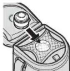
natural_image
Mechanical component diagram showing a knob and gear mechanism (no text or symbols)三脚座について
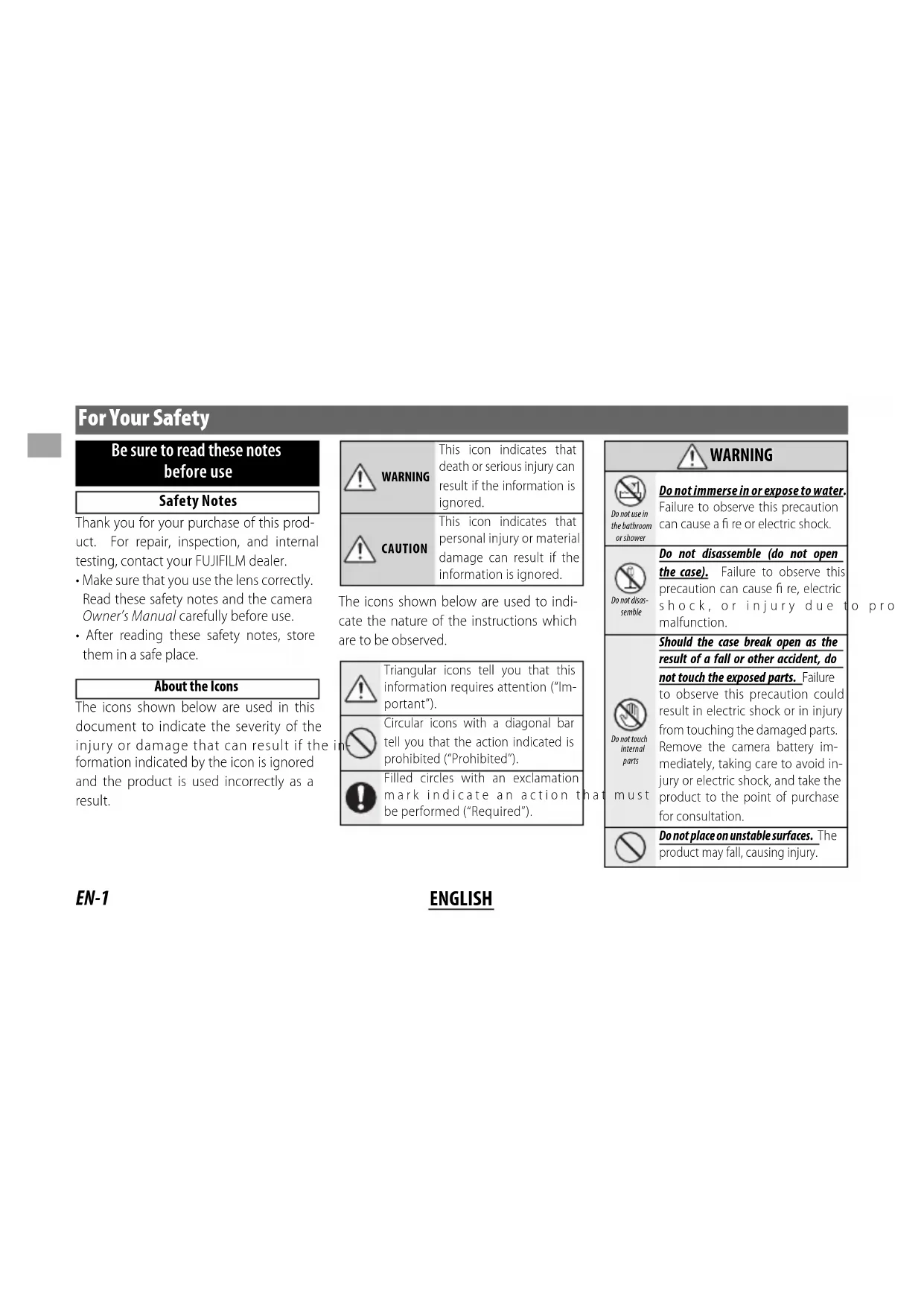
Be sure to read these notes before use
Safety Notes
Thank you for your purchase of this product. For repair, inspection, and internal testing, contact your FUJIFILM dealer.
• Make sure that you use the lens correctly. Read these safety notes and the camera Owner's Manual carefully before use.
• After reading these safety notes, store them in a safe place.
About the Icons
The icons shown below are used in this document to indicate the severity of the injury or damage that can result if the formation indicated by the icon is ignored and the product is used incorrectly as a result.
| This icon indicates that death or serious injury can result if the information is ignored. | |
| This icon indicates that personal injury or material damage can result if the information is ignored. |
The icons shown below are used to indicate the nature of the instructions which are to be observed.
| Triangular icons tell you that this information requires attention ("Important"). | |
| Circular icons with a diagonal bar tell you that the action indicated is prohibited ("Prohibited"). | |
| Filled circles with an exclamation mark indicate an action t be performed ("Required"). |
| WARNING | |
| Do not use in the bathroom or shower | Do not immerse in or expose to water.Failure to observe this precaution can cause a fi re or electric shock. |
| Do not disassemble | Do not disassemble (do not open the case).Failure to observe this precaution can cause fi re, electric shock, or injury due t malfunction. |
 must must | Should the case break open as the result of a fall or other accident, do not touch the exposed parts.Failure to observe this precaution could result in electric shock or in injury from touching the damaged parts.Remove the camera battery immediately, taking care to avoid in-jury or electric shock, and take the product to the point of purchase for consultation. |
 | Do not place on unstable surfaces. The product may fall, causing injury. |
 | WARNING | |
| Do not view the sun through the lens or camera viewfi nders. Failure to observe this precaution can cause permanent visual impairment. | ||
 | CAUTION | |
| Do not use or store in locations that are exposed to steam, or smoke or are very humid or extremely dusty. Fail-ure to observe this precaution can cause fi re or electric shock. | ||
Do  have in direct sunlight or in loca have in direct sunlight or in loca  subject to very high tem-perc subject to very high tem-perc  such as in a closed vehicle on c such as in a closed vehicle on c  day. Failure to observe this day. Failure to observe this  ution can cause fi re. ution can cause fi re. | ||
Keej [ZW72] of the reach of small chil-drel  his product could cause inju his product could cause inju  the hands of a child. the hands of a child. | ||
Do [B485] ndle with wet hands. Fail-ure  observe this precaution can cause electric shock. observe this precaution can cause electric shock. | ||
 | CAUTION | |
| ! | Keep the sun out of the frame when shooting backlit subjects. Sunlight focused into the camera when the sun is in or close to the frame can cause fi re or burns. | |
| ! | When the product is not in use, replace the lens caps and store out of direct sunlight. Sunlight focused by the lens can cause fi re or burns. | |
| ∅ | Do not carry the camera or lens while they are attached to a tripod. The product can fall or strike other objects, causing injury. | |
| ∅ | Do not rapidly rotate the camera while holding the grip. Your hand could strike the tripod or tripod collar foot, causing injury. | |
| ! | Before handling the camera, fully tighten or loosen the tripod collar lock screw according to whether the camera will be used in a fi xed orientation or rotated. If the screw is only partially tightened, the camera may move unexpectedly, causing injury. |
For Customers in the U.S.A.
Tested To Comply With FCC Standards
FOR HOME OR OFFICE USE
FCC Statement: This device complies with Part 15 of the FCC Rules. Operation is subject to the following two conditions: (1) This device may not cause harmful interference, and (2) this device must accept any interference received, including interference that may cause undesired operation.
CAUTION: This equipment has been tested and found to comply with the limits for a Class B digital device, pursuant to Part 15 of the FCC Rules. These limits are designed to provide reasonable protection against harmful interference in a residential installation. This equipment generates, uses, and can radiate radio frequency energy and, if not installed and used in accordance with the instructions, may cause harmful interference to radio communications. However, there is no guarantee that interference will not occur in a particular installation. If this equipment does cause harmful interference to radio or television reception, which can be determined by turning the equipment off and on, the user is encouraged to try to correct the interference by one or more of the following measures:
- Reorient or relocate the receiving antenna.
- Increase the separation between
the equipment and receiver.

EN-2
ENGLISH
- Connect the equipment into an outlet on a circuit different from that to which the receiver is connected.
- Consult the dealer or an experienced radio/TV technician for help.
- You are cautioned that any changes or modifications not expressly approved in this manual could void the user's authority to operate the equipment.
Notes on the Grant: To comply with Part 15 of the FCC Rules, this product must be used with a Fujifi Im-specific ed ferrite-core A/V cable, USB cable, and DC supply cord.
For Customers in Canada
CAN ICES-3 (B)/NMB-3(B)
CAUTION: This Class B digital apparatus complies with Canadian ICES-003.
IMPORTANT SAFETY INSTRUCTIONS
- Read these instructions.
- Keep these instructions.
- Heed all warnings.
- Follow all instructions.
- Do not use this apparatus near water (excluding waterproof products).
- Clean only with a dry cloth.
-
Do not block any ventilation openings. Install in accordance with the manufacturer's instructions.
-
Do not install near any heat sources such as radiators, heat registers, stoves, or other apparatus (including amplifiers) that produce heat.
- Protect the power cord from being walked on or pinched particularly at plugs, convenience receptacles, and the point where they exit from the apparatus.
- Only use attachments/accessories specified by the manufacturer.
- Unplug this apparatus during lightning storms or when unused for long periods of time.
- Refer all servicing to qualified service personal. Servicing is required when the apparatus has been damaged in any way, such as power supply cord or plug is damaged, liquid has been spilled or objects have fallen into the apparatus, the apparatus has been exposed to rain or moisture, does not operate normally, or has been dropped.
Disposal of Electrical and Electronic Equipment in Private Households
In the European Union, Norway, Iceland and Liechtenstein: This symbol on the product, or in the manual and in the warranty, and/or on its packaging indicates that this product shall not be treated as household waste. Instead it should be taken to an applicable collection point for the recycling of electrical and electronic equipment.
By ensuring this product is disposed of correctly, you will help prevent potential negative consequences to the environment and human health, which could otherwise be caused by inappropriate waste handling of this product.
The recycling of materials will help to conserve natural resources. For more detailed information about recycling this product, please contact your local city office, your household waste disposal service or the shop where you purchased the product.
In Countries Outside the European Union, Norway, Iceland and Liechtenstein: If you wish to discard this product, including the batteries or accumulators, please contact your local authorities and ask for the correct way of disposal.
Australian RCM

Before Using This Product
The lens may not perform as expected and some features may not be available with older versions of the camera fi rmware. Be sure to update the camera fi rmware to the latest version. Instructions on viewing the camera fi rmware version and updating camera fi rmware are available from the following website:
http://www.fujifilm.com/support/digital_cameras/software/#firmware
If you do not have access to a computer, support is available from the local distributor listed in the "FUJIFILM Worldwide Network" material provided with your camera.
Product Care
- When using a lens hood, do not pick up or hold the camera using only the hood.
- Keep the lens signal contacts clean.
- Use a blower to remove dust and lint from the
glass surfaces of the lens or fi lter. To remove smudges and fi ingerprints, apply a small amount of lens cleaner to a soft, clean cotton cloth or lens-cleaning tissue and clean from the center outwards using a circular motion, taking care not to leave smears or touch the glass with your fi ngers.
- Never use organic solvents such as paint thinner or benzene to clean the lens.
- Attach the front and rear caps when the lens is not in use.
- Store the lens and fi Iter in cool, dry locations to prevent mold and rust. Do not store in direct sunlight or with naphtha or camphor moth balls.
- Keep the lens dry. Rusting can cause irreparable damage. Wipe off rain and water droplets.
• Leaving the lens in extremely hot locations could cause damage or warping. - Note that depending on the positions of the camera and tripod, the hand holding the camera grip may contact the tripod or tripod collar foot when the camera is rotated.
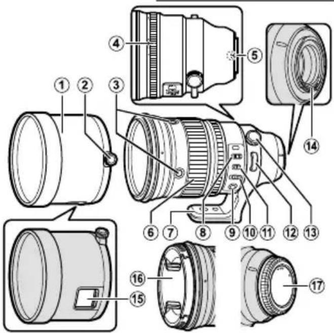
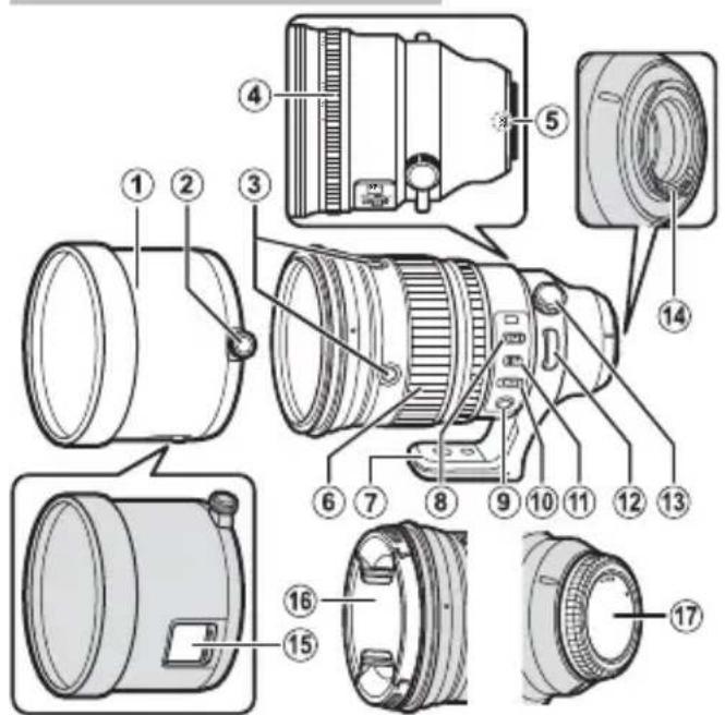
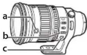
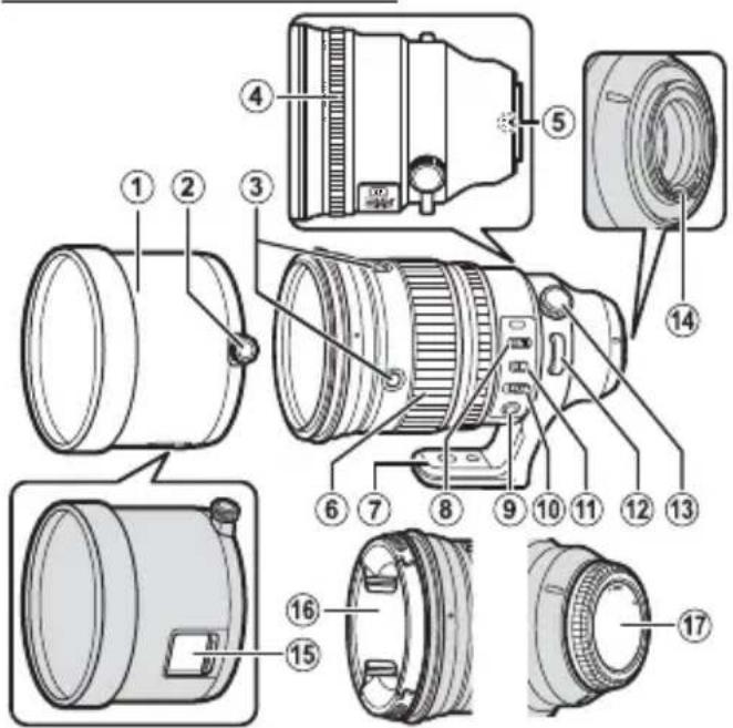
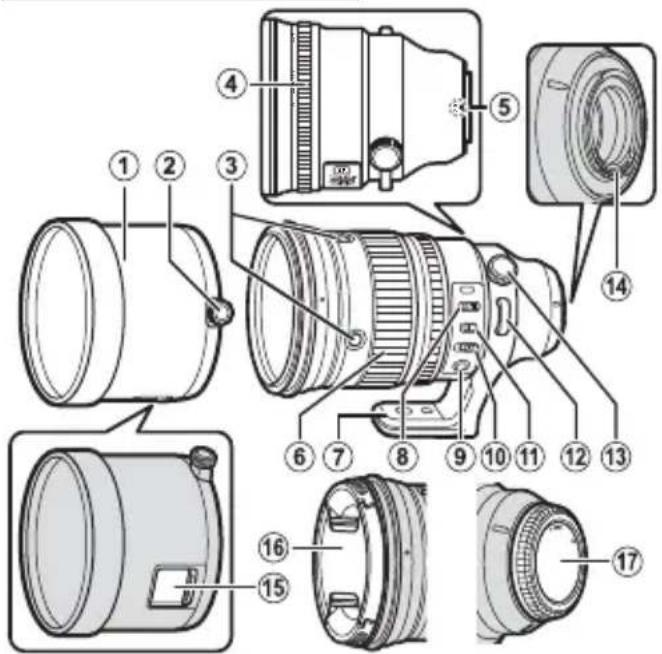
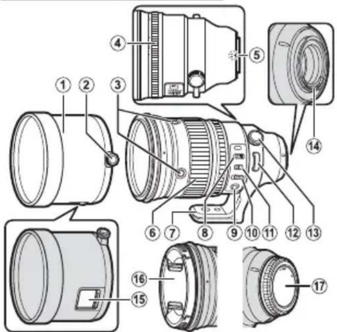
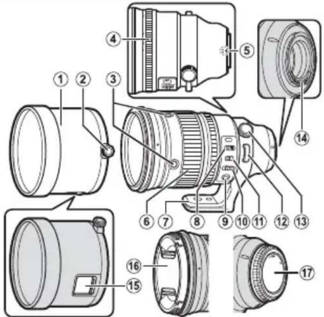
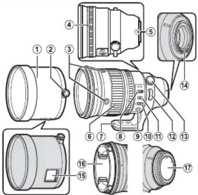
Parts of the Lens
XF200mmF2 R LM OIS WR
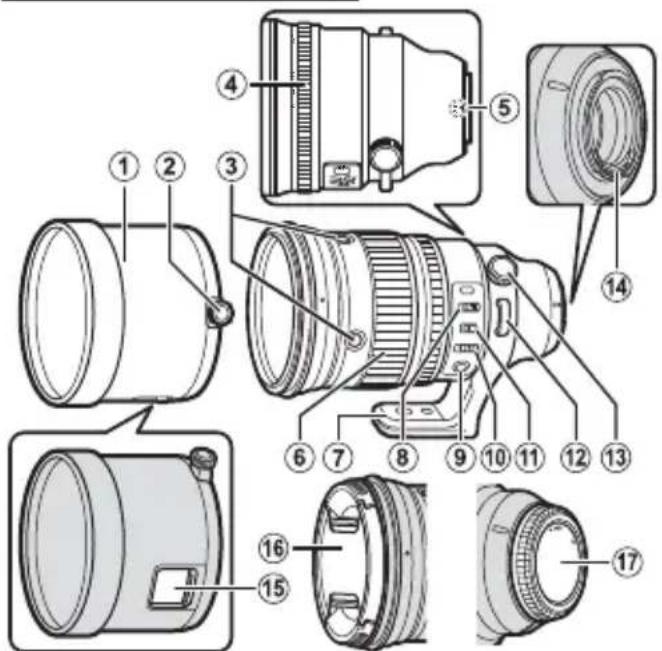
① The lens mount includes a rubber ring to ensure that the lens remains dust- and splash-proof. The ring can be replaced for a fee at any FUJIFILM service center.
① Lens hood
② Hood lock knob
③ Focus control button (×4)
④ Aperture ring
⑤ Mounting marks (focal length)
⑥ Focus ring
⑦ Tripod collar foot
⑧ Focus range selector
⑨ Focus preset button
⑩ Focus selector
⑪ O.I.S. switch
⑫ Strap eyelet
⑬ Lock knob
⑭ Lens signal contacts
⑮ Filter access port
⑯ Front lens cap
⑰ Rear lens cap
XF1.4X TC F2 WR
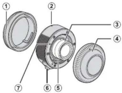
① Rear lens cap
② Camera mounting index
③ Protruding portion
④ Front lens cap
⑤ Lens signal contacts
⑥ Lens removal lever
⑦ Lens mounting index
① Never touch the protruding portion, because the shape is very precise.
① The lens mount includes a rubber ring to ensure that the lens remains dust- and splash-proof. The ring can be replaced for a fee at any FUJIFILM service center.
① Using the teleconverter with a macro extension tube may cause a malfunction.
Supplied Accessories
XF200mmF2 R LM OIS WR
- Front lens cap
- Rear lens cap
-
Lens hood
-
Shoulder strap
- Lens case
XF1.4X TC F2 WR
- Front lens cap
- Rear lens cap
- Lens pouch
ENGLISH
EN-6
Attaching the Lens
See the camera manual for information on attaching and removing lenses.
① This lens is for use exclusively with FUJIFILM X mounts and cannot be used with G mounts.
Attaching the Shoulder Strap
Attach the strap to the two strap eyelets as shown.
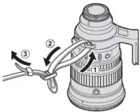
① To avoid dropping the lens, be sure the strap is correctly secured.
EN-7
ENGLISH
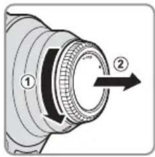
Removing the Caps
Remove the caps as shown.
Attaching the Hood
When attached, lens hoods reduce glare and protect the front lens element.
- Loosen the hood lock knob by ro counterclockwise.

- Slide the hood onto the lens until it contacts the raised ridge.
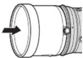
natural_image
Technical line drawing of a cylindrical mechanical component with a directional arrow indicating flow or direction (no text or symbols)- Tighten the lock knob.
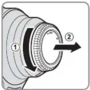
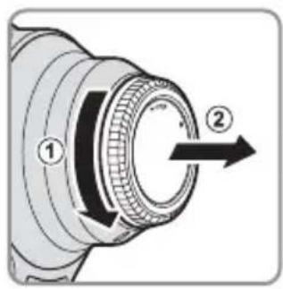
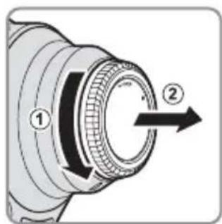
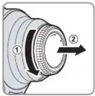
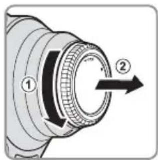
Removing the Hood
- Loosen the hood knob by counterclockwise.

- Slide the hood straight forward off the lens.
natural_image
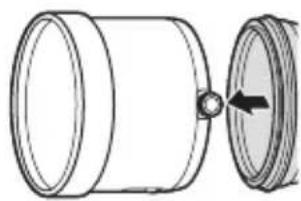
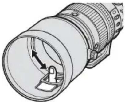
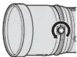
Diagram of a cylindrical mechanical component with a circular end and an arrow indicating rotation (no text or symbols)The Polarizing Filter
To access the polarizing filter, open the filter access port cover.
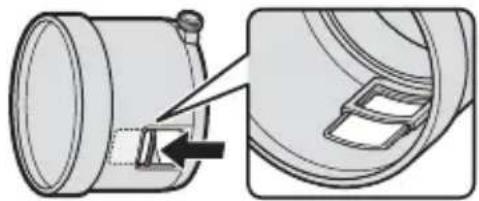
natural_image
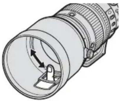
Technical illustration of a mechanical component with an arrow indicating a step, shown from two views (no text or symbols present)The filter can be rotated by inserting a finger through the access port.

natural_image
Technical line drawing of a cylindrical mechanical component with internal components and directional arrows (no text or symbols)EN-9
ENGLISH
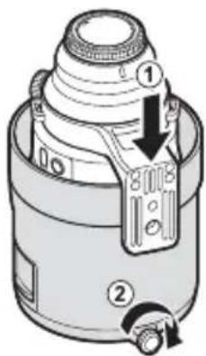
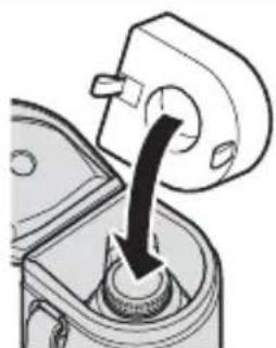
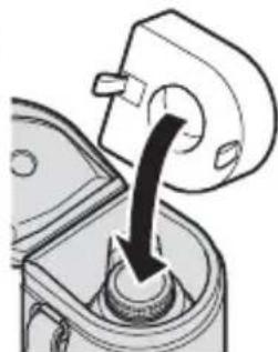
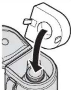
Using the Lens Case
1 Reverse and attach the hood, keeping tripod collar foot aligned with the hood lock knob.
3 Fit the deepest hollow in the cushion over the lens cap.
natural_image
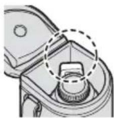
Mechanical component diagram showing a lever mechanism with a black arrow indicating direction (no text or symbols)2 Insert the assembly with the bottom of the tripod collar foot in a corner of the case.
natural_image
Technical diagram of a mechanical component with a dashed circular annotation highlighting a feature (no text or symbols present)① Ensure that the cushion fi ts snugly with no gaps. ① Be sure to use the cushion even if the teleconverter is not inserted.
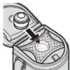
4 Insert the teleconverter with its rear cap in the hollow in the cushion and cover it with the net.
natural_image
Mechanical component diagram showing a knob and gear mechanism (no text or symbols)① Be sure to attach the lens caps before putting the lens
in the case.
The lens can be inserted with the teleconverter attached.
① Fit the assembly into the hollows inside the case.
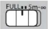
The Focus Range Selector
Choose the focus range for autofocus.

• FULL: Focus on subjects at any distance.
- 5m–∞: Focus on subjects at distances of 5 m or more. Focus is faster than when FULL is selected.
Optical Image Stabilization (OIS)
To use optical image stabilization, slide the O.I.S. switch to ON.
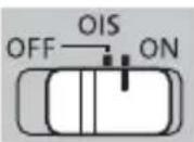
Because image stabilization is also effective in reducing blur caused by the motion of the mechanical shutter, we recommend that you slide the O.I.S. switch to ON even when using a tripod.
The Focus Control Buttons, Focus Selector, and Focus Preset Button
AF-LOCK (Focus Lock)
1 Slide the focus selector (b) to AF-L.
2 Press any of the focus control buttons (a) to lock focus at the current position.
◆ Focus can also be locked using camera controls.
Autofocus (AF-ON)
1 Slide the focus selector (b) to AF.
2 The focus control buttons (a) will now perform the same function as the camera AF-ON button.
EN-11
ENGLISH
PRESET (Focus Preset)
① Creating a Focus Preset
To save the current focus position in the lens as a focus preset, press the focus preset button (c).
The focus distance can be saved with the focus selector (b) in any position.
② Recalling the Focus Preset
1 Slide the focus selector (b) to PRESET.
2 Press any focus control button (a) to restore the preset focus position.
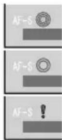
Status is shown in the camera LCD monitor.
- Preset saved (green)
- Preset recalled (green)
- Preset save/load error (blinks red)
The lens will store the preset focus distance even when the camera is off or the lens is removed from the camera.
If ON is selected for AF+MF, pressing a focus control button will return the lens to the preset focus position even while the shutter button is pressed halfway.
Using the Teleconverter
Exposure
- Attaching the teleconverter slows the lens by the equivalent of 1 f-stop.
- The actual aperture differs from that shown by the lens aperture ring. The camera shows the correct value.
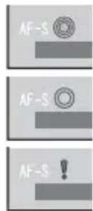
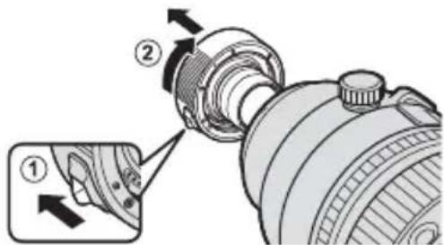
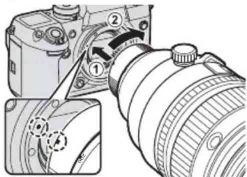
Attachment
1 Turn the camera off.
2 Align the lens mounting index on the teleconverter with the mounting mark on the lens (①) and rotate the teleconverter in the direction shown (②) until it clicks into place.
EN-13
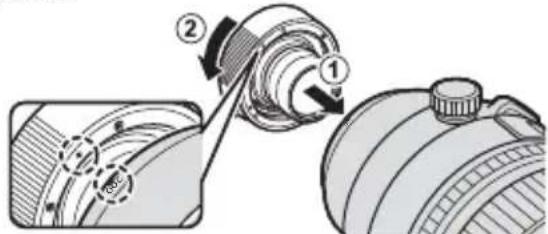
3 Align the camera mounting index on the teleconverter with the index on the camera (①) and rotate the lens and teleconverter assembly in the direction shown (②) until it clicks into place.

natural_image
Technical illustration of a DSLR camera with adjustment parts (no text or symbols)① Be careful not to press the lens removal lever on the teleconverter.
ENGLISH
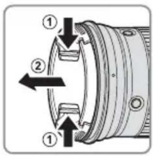
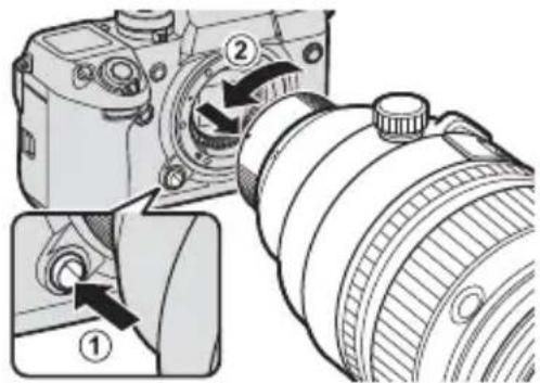
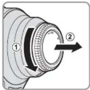
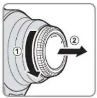
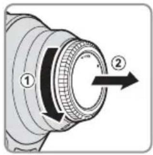
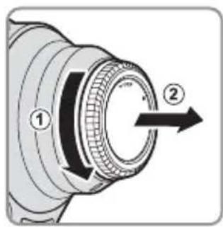
Removal
1 Turn the camera off.
2 Keeping the camera lens release button pressed (①), rotate the teleconverter and lens assembly in the direction shown and remove it from the camera (②).
3 Keeping the lens removal lever pressed (①), rotate the teleconverter in the direction shown and remove it from the lens (②).
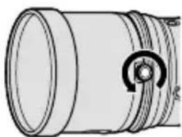
The Tripod Collar
To go from landscape to portrait orientation or back again without removing the tripod, loosen the lock knob and rotate the camera and lens assembly 90° until it clicks into place.
① Tighten the knob securely to prevent the camera rotating unexpectedly.
ENGLISH
EN-14
Specifications
| Type XF200mmF2 R LM OIS WR XF1.4X TC F2 WR | ||
| Lens construction | 19 elements in 14 groups (includes 2 extra-low-dispersion elements and 1 super extra-low-dispersion element) | 7 elements in 4 groups (includes 1 aspherical element) |
| Focal length (35 mm format equivalent) | f=200 mm (305mm) | — |
| Angle of view 8.1° — | ||
| Max. aperture f/2 — | ||
| Min. aperture f/22 — | ||
| Aperture control | ||
| Number of blades | 9 (rounded diaphragm opening) | — |
| Stop size | 13 EV (22 stops) | |
| Focus range (measured from focal plane) | 1.8 m-infinity | — |
| Max. magnification | 0.12 × | — |
| External dimensions: Diameter × Length (approx.) | ∅122 × 205.5 mm(distance from camera lens mount fl ange) | ∅58 × 15 mm(distance from camera lens mount fl ange) |
| Weight (approx.) | 2265 g (excluding lens caps and hoods) | 130 g (excluding lens caps) |
| Filter size | ∅105 mm | — |
① Improvements may result in unannounced changes to specifications and appearance.
① Owing to how this lens is constructed, the "Distance indicator" displayed by the camera may in some cases differ from the actual focus distance. Use the "Distance indicator" as a guide only.
① The teleconverter is exclusively for use with cameras that support a maximum aperture of f/2.
Turn the camera off before removing the lens. Turning the camera off locks the internal parts of the lens.
EN-15
ENGLISH
Pour votre sécurité
http://www.fujifilm.com/support/digital_cameras/software/#firmware
XF200mmF2 R LM OIS WR

XF200mmF2 R LM OIS WR
natural_image
Simple line drawing of a cylindrical mechanical component with a curved arrow indicating rotation (no text or symbols)natural_image
Pure mechanical component diagram without any text, numbers, or symbolsnatural_image
Technical line drawing of a cylindrical mechanical component with a circular feature on the side (no text or symbols)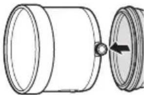
natural_image
Technical line drawing of a cylindrical mechanical component with a side view showing a hole and an arrow indicating direction (no text or symbols)natural_image
Technical illustration of a cylindrical mechanical component with a close-up view showing internal components (no text or symbols)natural_image
Technical line drawing of a cylindrical mechanical component with internal components and directional arrows (no text or symbols)FRANÇAIS
FR-9
natural_image
Mechanical component diagram showing a rotating shaft and housing (no text or symbols)natural_image
Diagram of a DSLR camera with adjustment parts, showing lens and frame (no text or symbols)http://www.fujifilm.com/support/digital_cameras/software/#firmware
XF200mmF2 R LM OIS WR

XF200mmF2 R LM OIS WR

natural_image
Simple line drawing of a cylindrical mechanical component with a curved arrow indicating rotation (no text or symbols)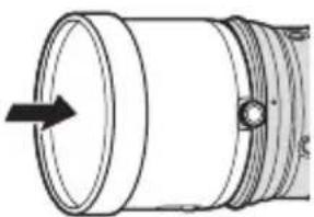
natural_image
Technical line drawing of a cylindrical mechanical component with a directional arrow indicating flow or movement (no text or symbols)Abnehmen der Haube
natural_image
Technical line drawing of a cylindrical mechanical component with a circular feature on the side (no text or symbols)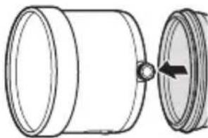
natural_image
Technical line drawing of a cylindrical mechanical component with an arrow indicating a joint or insertion (no text or symbols present)Der Polfi Iter
natural_image
Technical illustration of a mechanical component with an arrow indicating a step, shown from two views (no text or symbols present)natural_image
Technical line drawing of a mechanical component with internal channels and a handle (no text or symbols)DE-9
DEUTSCH
natural_image
Mechanical component diagram showing a bolt inserted into a housing (no text or symbols visible)natural_image
Mechanical component diagram showing a rotating shaft and housing (no text or symbols)natural_image
Mechanical component diagram showing a knob and gear mechanism (no text or symbols)DE-13
natural_image
Diagram of a DSLR camera with adjustment parts, showing lens and frame (no text or symbols)http://www.fujifilm.com/support/digital_cameras/software/#firmware
XF200mmF2 R LM OIS WR
XF200mmF2 R LM OIS WR
natural_image
Simple line drawing of a cylindrical mechanical component with a circular knob (no text or symbols)natural_image
Pure mechanical component diagram without any text, numbers, or symbolsnatural_image
Technical line drawing of a cylindrical mechanical component with a circular feature on the side (no text or symbols)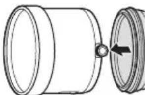
natural_image
Technical line drawing of a cylindrical mechanical component with an arrow indicating a joint or transition (no text or symbols present)natural_image
Technical illustration of a mechanical component with an arrow indicating a step, shown from two views (no text or symbols present)natural_image
Technical line drawing of a cylindrical mechanical component with internal channels and a handle (no text or symbols)ESPAÑOL
natural_image
Close-up of a mechanical component with a dashed circular annotation highlighting a specific part (no text or symbols present)natural_image
Mechanical component diagram showing a rotating shaft and housing (no text or symbols)natural_image
Mechanical component diagram showing a knob and gear mechanism (no text or symbols)http://www.fujifilm.com/support/digital_cameras/software/#firmware
XF200mmF2 R LM OIS WR

XF200mmF2 R LM OIS WR
• Voorste lensdop
- Achterste lensdop
• Zonnekap
• Schouderriem
- Objectieftas
XF1.4X TC F2 WR
• Voorste lensdop
- Achterste lensdop
- Lenszak
NEDERLANDS
NL-6
Een lens bevestigen

De zonnekap bevestigen
natural_image
Simple line drawing of a cylindrical mechanical component with a circular arrow symbol on one end (no text or labels)natural_image
Technical line drawing of a cylindrical mechanical component with a circular arrow indicating rotation (no text or symbols)
natural_image
Technical line drawing of a cylindrical mechanical component with a side view showing a circular opening and an arrow indicating direction (no text or symbols)natural_image
Technical illustration of a mechanical component with a close-up view showing a pin inserted into a housing (no text or symbols present)natural_image
Technical line drawing of a cylindrical device with internal components and directional arrows indicating flow or movement (no text or symbols)NL-9
NEDERLANDS
natural_image
Technical diagram of a mechanical component with a dashed circular annotation highlighting a feature (no text or symbols present)natural_image
Mechanical component diagram showing a rotating shaft and housing (no text or symbols)natural_image
Mechanical component diagram showing a knob and gear mechanism (no text or symbols)Optical Image Stabilization (OIS)
NL-13
NEDERLANDS
natural_image
Diagram of a DSLR camera with adjustment parts, showing lens and frame (no text or symbols)De statiefgondel
http://www.fujifilm.com/support/digital_cameras/software/#firmware
XF200mmF2 R LM OIS WR

① Bakre objektivlock
② Kamerafästets index
③ Utskjutande del
④ Främre objektivlock
⑤ Objektivsignalkontakter
⑥ Objektivborttagningsspak
⑦ Objektivfästets index
XF200mmF2 R LM OIS WR
- Främre objektivlock • Bärrem
- Bakre objektivlock
- Objektivfodral
- Motljusskydd
XF1.4X TC F2 WR
natural_image
Simple line drawing of a cylindrical mechanical component with a curved knob (no text or symbols)natural_image
Technical line drawing of a cylindrical mechanical component with a black arrow indicating direction (no text or symbols)- Dra åt låsvredet.
natural_image
Technical line drawing of a cylindrical mechanical component with a curved internal feature (no text or symbols)natural_image
Diagram of a cylindrical mechanical component with a side view showing a circular opening and a central hole (no text or symbols)Polariseringsfi Itret
natural_image
Technical illustration of a cylindrical mechanical component with a close-up view showing internal components (no text or symbols)natural_image
Technical line drawing of a cylindrical device with internal components and directional arrows indicating flow or movement (no text or symbols)SVENSKA
natural_image
Technical diagram of a mechanical component with a dashed circular annotation highlighting a feature (no text or symbols present)natural_image
Mechanical component diagram showing a rotating shaft and housing (no text or symbols)natural_image
Technical diagram of a mechanical component with a knob and central hub (no text or symbols)natural_image
Technical illustration of a DSLR camera with adjustment knobs and lens components (no text or symbols)Stativkragen
http://www.fujifilm.com/support/digital_cameras/software/#firmware
XF200mmF2 R LM OIS WR

① Bakre objektivdeksel
② Kameraets monteringsmerke
③ Fremspringende del
④ Fremre objektivdeksel
⑤ Objektivets signalkontakter
⑥ Linsens utløserhendel
⑦ Linsens monteringsmerke
XF200mmF2 R LM OIS WR
• Fremre linsedeksel • Skulderstropp
• Bakre linsedeksel • Linsebeholder
- Solblender
XF1.4X TC F2 WR
• Fremre linsedeksel • Linselomme
• Bakre linsedeksel
NORSK
NO-6
Feste linsen
natural_image
Simple line drawing of a cylindrical mechanical component with a curved arrow indicating rotation (no text or symbols)natural_image
Technical line drawing of a cylindrical mechanical component with a black arrow indicating direction (no text or symbols)natural_image
Technical line drawing of a cylindrical mechanical component with a circular feature on the side (no text or symbols)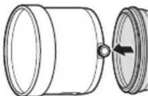
natural_image
Diagram of a cylindrical mechanical component with a side view showing a pin and arrow (no text or symbols)natural_image
Technical illustration of a mechanical component with a close-up view showing a pin inserted into a housing (no text or symbols present)natural_image
Technical line drawing of a cylindrical optical lens with internal components and directional arrows indicating flow or movement (no text or symbols)NO-9
NORSK
natural_image
Technical diagram of a mechanical component with a dashed circular annotation highlighting a specific section (no text or symbols present)natural_image
Mechanical component diagram showing a rotating shaft and housing (no text or symbols)natural_image
Mechanical component diagram showing a knob and gear mechanism (no text or symbols)Linsen kan settes inn med montert telekonverter.
Fokusområdevelgeren
Velg fokusområde for autofokus.
• FULL: Fokuser på motiver uansett avstand.
- 5m–∞: Fokuser på motiver som er 5 m unna eller mer. Fokus er raskere enn när FULL er valgt.
Optisk bildestabilisering (OIS)
NO-13
3 Juster kameraets monteringsmerke på telekonverteren etter merket på kameraet (①) og roter linsen med montert telekonverter i den viste retningen (②) til den klikker på plass.
natural_image
Technical illustration of a DSLR camera with adjustment knobs and lens components (no text or symbols)Stativkrage
http://www.fujifilm.com/support/digital_cameras/software/#firmware
XF200mmF2 R LM OIS WR

XF200mmF2 R LM OIS WR

natural_image
Simple line drawing of a cylindrical mechanical component with a curved arrow indicating rotation (no text or symbols)natural_image
Pure mechanical component diagram without any text, numbers, or symbolsnatural_image
Technical line drawing of a cylindrical mechanical component with a circular feature on the side (no text or symbols)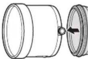
natural_image
Technical line drawing of a cylindrical mechanical component with an arrow indicating a joint or insertion (no text or symbols present)Polarisaatiosuodin
natural_image
Technical illustration of a cylindrical mechanical component with a close-up view showing internal components (no text or symbols)natural_image
Technical line drawing of a cylindrical mechanical component with internal channels and a handle (no text or symbols)SUOMI
FI-9
natural_image
Mechanical component diagram showing a rotating shaft and housing (no text or symbols)natural_image
Mechanical component diagram showing a knob and gear mechanism (no text or symbols)natural_image
Diagram of a DSLR camera with adjustment knobs and lens components (no text or symbols)Jalustarengas
XF200mmF2 R LM OIS WR

XF200mmF2 R LM OIS WR
Установка бленды
natural_image
Simple line drawing of a cylindrical mechanical component with a circular knob (no text or symbols)natural_image
Technical line drawing of a cylindrical mechanical component with a black arrow indicating direction (no text or symbols)natural_image
Technical line drawing of a cylindrical mechanical component with a curved arrow indicating rotation (no text or symbols)natural_image
Diagram of a cylindrical mechanical component with a side view showing an arrow indicating rotation (no text or symbols present)natural_image
Technical illustration of a mechanical component with a close-up view showing a pin inserted into a housing (no text or symbols present)natural_image
Technical line drawing of a cylindrical device with internal components and directional arrows indicating flow or movement (no text or symbols)RU-9
РУССКИЙ
natural_image
Close-up of a mechanical component with a dashed circular annotation highlighting a specific part (no text or symbols present)natural_image
Mechanical component diagram showing a rotating shaft and housing (no text or symbols)natural_image
Mechanical component diagram showing a knob and gear mechanism (no text or symbols)RU-13
natural_image
Diagram of a DSLR camera with adjustment parts, showing lens and frame assembly (no text or symbols)Кольцо штатива
http://www.fujifilm.com/support/digital_cameras/software/#firmware
XF200mmF2 R LM OIS WR

XF200mmF2 R LM OIS WR

Montaggio paraluce
natural_image
Simple line drawing of a cylindrical mechanical component with a circular knob (no text or symbols)natural_image
Technical line drawing of a cylindrical mechanical component with a black arrow indicating direction (no text or symbols)natural_image
Technical line drawing of a cylindrical mechanical component with a circular feature on its side (no text or symbols)
natural_image
Technical line drawing of a cylindrical mechanical component with an arrow indicating a joint or insertion (no text or symbols present)natural_image
Technical illustration of a cylindrical mechanical component with an arrow indicating a fastening or adjustment, shown from two views (no text or symbols present)natural_image
Technical line drawing of a cylindrical mechanical component with internal channels and mounting brackets (no text or symbols)ITALIANO
natural_image
Technical diagram of a mechanical component with a dashed circular annotation highlighting a specific section (no text or symbols present)natural_image
Mechanical component diagram showing a rotating shaft and housing (no text or symbols)natural_image
Mechanical component diagram showing a knob and gear mechanism (no text or symbols)La fl angia treppiedi
http://www.fujifilm.com/support/digital_cameras/software/#firmware
XF200mmF2 R LM OIS WR
① Bagerste objektivdæksel
② Kameraets monteringsindeks
③ Del, der stikker frem
④ Forreste objektivdæksel
⑤ Objektivets signalkontakter
⑥ Håndtag til objektivfj ernelse
⑦ Objektivets monteringsindeks
XF200mmF2 R LM OIS WR

natural_image
Simple line drawing of a cylindrical mechanical component with a circular knob (no text or symbols)natural_image
Technical line drawing of a cylindrical mechanical component with a black arrow indicating direction (no text or symbols)- Spænd läsegrebet.
natural_image
Technical line drawing of a cylindrical mechanical component with a circular feature on the side (no text or symbols)natural_image
Technical line drawing of a cylindrical mechanical component with an arrow indicating a joint or insertion (no text or symbols present)Polarisationsfi Iteret
natural_image
Technical illustration of a mechanical component with an arrow indicating a step, shown from two views (no text or symbols present)natural_image
Technical line drawing of a cylindrical mechanical component with internal components and directional arrows (no text or symbols)DA-9
DANSK
natural_image
Mechanical component diagram showing a dial indicator and housing (no text or symbols)natural_image
Mechanical component diagram showing a rotating shaft and housing (no text or symbols)natural_image
Technical diagram of a mechanical component with a knob and central hub (no text or symbols)DA-13
natural_image
Technical illustration of a DSLR camera with adjustment parts (no text or symbols)Stativkraven
http://www.fujifilm.com/support/digital_cameras/software/#firmware
XF200mmF2 R LM OIS WR

XF200mmF2 R LM OIS WR

natural_image
Simple line drawing of a cylindrical mechanical component with a circular knob (no text or symbols)natural_image
Technical line drawing of a cylindrical mechanical component with a black arrow indicating direction (no text or symbols)natural_image
Technical line drawing of a cylindrical mechanical component with a circular feature on the side (no text or symbols)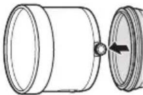
natural_image
Technical line drawing of a cylindrical mechanical component with an arrow indicating a joint or insertion (no text or symbols present)Filtr polaryzacyjny
natural_image
Technical illustration of a mechanical component with an arrow indicating a step, shown from close-up (no text or symbols)natural_image
Technical line drawing of a mechanical component with internal flow arrows (no text or symbols)POLSKI
PL-9
natural_image
Technical diagram of a mechanical component with a dashed circular annotation highlighting a feature (no text or symbols present)natural_image
Mechanical component diagram showing a rotating shaft and housing with a black arrow indicating rotation direction (no text or symbols)natural_image
Mechanical component diagram showing a knob and gear mechanism (no text or symbols)natural_image
Diagram of a DSLR camera with adjustment parts, showing lens and frame (no text or symbols)Kołnierz statywu

缓冲材: PE-LD 04
包装袋:PE-HD 02
PE-LD 04
ZHS-3
中文简
使用本产品前
http://www.fujifilm.com/support/digital_cameras/software/#firmware
XF200mmF2 R LM OIS WR
XF200mmF2 R LM OIS WR
- 镜头前盖
- 肩带
- 镜头后盖
- 镜头包
- 镜头遮光罩
XF1.4X TC F2 WR
- 镜头前盖
- 镜头袋
- 镜头后盖
中文简
ZHS-6
安装镜头
安装遮光罩
natural_image
Simple line drawing of a cylindrical mechanical component with a circular knob (no text or symbols)natural_image
Technical line drawing of a cylindrical mechanical component with a directional arrow indicating flow or movement (no text or symbols)- 旋紧锁定旋钮。
取下遮光罩
natural_image
Technical line drawing of a cylindrical mechanical component with a curved arrow indicating rotation (no text or symbols)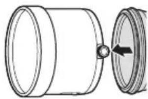
natural_image
Diagram of a cylindrical mechanical component with a circular end and an arrow indicating rotation (no text or symbols)偏光滤镜
natural_image
Technical illustration of a mechanical component with an arrow indicating a step, shown from two views (no text or symbols present)随后,将手指插入操作端口即可旋转滤镜。
natural_image
Technical line drawing of a cylindrical device with internal components and directional arrows indicating flow or movement (no text or symbols)ZHS-9
中文简
使用镜头包
使镜头盖贴住内衬上最深的凹陷处。
natural_image
Mechanical component diagram showing a rotating shaft and housing (no text or symbols)natural_image
Technical diagram of a mechanical component with a dashed circular annotation highlighting a feature (no text or symbols present)natural_image
Close-up of a mechanical component with a knob and textured surface (no visible text or symbols)natural_image
Diagram of a DSLR camera with adjustment parts, showing lens and frame (no text or symbols)三脚架固定环
http://www.fujifilm.com/support/digital_cameras/software/#firmware
XF200mmF2 R LM OIS WR
XF200mmF2 R LM OIS WR
安裝遮光罩
natural_image
Simple line drawing of a cylindrical mechanical component with a curved arrow indicating rotation (no text or symbols)natural_image
Pure mechanical diagram of a cylindrical component with a directional arrow, no text or symbols present- 旋緊鎖定旋鈕。
取下遮光罩
- 逆時針旋轉遮光罩鎖定旋鈕將其擰鬆。
- 將遮光罩從鏡頭直接向前滑出。
natural_image
Technical line drawing of a cylindrical mechanical component with a curved arrow indicating rotation (no text or symbols)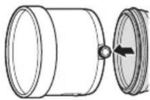
natural_image
Diagram of a cylindrical mechanical component with a side view showing a circular feature and an arrow indicating rotation (no text or symbols)偏光濾鏡
若要操作偏光濾鏡,請打開濾鏡操作埠蓋。

natural_image
Technical illustration of a mechanical component with a close-up view showing internal structure (no text or symbols)隨後,將手指插入操作埠中即可旋轉濾鏡。
natural_image
Technical line drawing of a cylindrical optical lens with internal components and directional arrows (no text or symbols)ZHT-8
中文繁體
使用鏡頭包
3 使鏡頭蓋貼住內襯上最深的凹陷處。
natural_image
Mechanical component diagram showing a rotating shaft and housing (no text or symbols)natural_image
Mechanical component diagram showing a dial and handle assembly (no text or symbols)natural_image
Close-up of a mechanical component with a knob and textured surface (no visible text or symbols)ZHT-12
中文繁體
拆卸
1 關閉相機。
三腳架固定環
http://www.fujifilm.com/support/digital_cameras/.software/#firmware
XF200mmF2 R LM OIS WR
XF200mmF2 R LM OIS WR
- 앞렌즈캡
-어깨 스트랩
·렌즈뒷 커버
·렌즈케이스
-렌즈 후드
KO-6
XF1.4X TC F2 WR
- 앞렌즈캡
-렌즈 파우치
·렌즈뒷 커버
한글
렌즈 부착
후드 부착
natural_image
Simple line drawing of a cylindrical mechanical component with a curved knob (no text or symbols)natural_image
Pure mechanical component diagram without any text, numbers, or symbols· 잠금 손잡이를 조여줍니다.
후드제거
natural_image
Technical line drawing of a cylindrical mechanical component with a curved internal feature (no text or symbols)
natural_image
Diagram of a cylindrical mechanical component with a side view showing a circular feature and an arrow indicating direction (no text or symbols)편광 필터
natural_image
Technical illustration of a mechanical component with a close-up view showing internal structure (no text or symbols)natural_image
Technical line drawing of a cylindrical optical lens with internal components and directional arrows (no text or symbols)한글
렌즈케이스사용
natural_image
Technical line drawing of a mechanical component with a dashed circular annotation highlighting a section (no text or symbols present)natural_image
Mechanical component diagram showing a rotating shaft and housing (no text or symbols)natural_image
Mechanical component diagram showing a knob and gear mechanism (no text or symbols)natural_image
Technical illustration of a DSLR camera with adjustment knobs and lens components (no text or symbols)삼각대 칼라
3
AR-13
عربي
natural_image
Mechanical component diagram showing a rotating shaft and housing with a black arrow indicating rotation direction (no text or symbols)natural_image
Close-up of a mechanical component with a knob and textured surface, no visible text or symbolsnatural_image
Mechanical component diagram showing a dial indicator and handle (no text or symbols)natural_image
Technical illustration of a mechanical component with a close-up view showing a pin inserted into a housing (no text or symbols present)natural_image
Technical line drawing of a cylindrical mechanical component with internal channels and a valve mechanism (no text or symbols)زالالة الواقية
natural_image
Technical line drawing of a cylindrical mechanical component with a circular inset showing a curved feature (no text or symbols)natural_image
Diagram of a cylindrical mechanical component with a central hole and an arrow indicating direction (no text or symbols)• لى الأمام
حتى تخرج من العدسة.
تركيب Timestampية
natural_image
Simple line drawing of a cylindrical mechanical component with a curved arrow indicating rotation (no text or symbols)natural_image
Pure mechanical diagram of a cylindrical component with a directional arrow, no text or symbols presentتركيب الاددسة
XF200mmF2 R LM OIS WR
XF200mmF2 R LM OIS WR