
MTRT8 - Router BLACK & DECKER - Free user manual and instructions
Find the device manual for free MTRT8 BLACK & DECKER in PDF.
| Brand | Black & Decker |
| Model | MTRT8 |
| Product type | Router (wood router) |
| Power | 14.4 V battery (cordless) |
| No-load speed | 0 - 9000 min⁻¹ |
| Weight | 1.3 kg (14.4V version) / 1.5 kg (Max version) |
| Collet size | 1/4 inch (6.35 mm) |
| Max bit diameter | 22 mm |
| Max depth of cut | 25.4 mm |
| Sound pressure level | 78.3 dB(A) (uncertainty 3 dB) |
| Sound power level | 89 dB(A) (uncertainty 3 dB) |
| Vibration (total value) | < 2.5 m/s² (uncertainty 1.5 m/s²) |
| Warranty | 24 months (applicable conditions) |
| Main functions | Routing, grooving, rabbeting, chamfering, engraving, edge shaping |
| Maintenance and cleaning | Clean after use, remove battery before maintenance, use a dust mask |
| Safety | Wear goggles and mask, do not touch hot blade, use insulated gripping surfaces |
| Spare parts and repairability | Replacement bits, dust extraction adapter, collet, tightening wrench |
| General information | Household use only, do not use for metal, do not use in fixed mode |
Frequently Asked Questions - MTRT8 BLACK & DECKER
User questions about MTRT8 BLACK & DECKER
0 question about this device. Answer the ones you know or ask your own.
Ask a new question about this device
Download the instructions for your Router in PDF format for free! Find your manual MTRT8 - BLACK & DECKER and take your electronic device back in hand. On this page are published all the documents necessary for the use of your device. MTRT8 by BLACK & DECKER.
USER MANUAL MTRT8 BLACK & DECKER
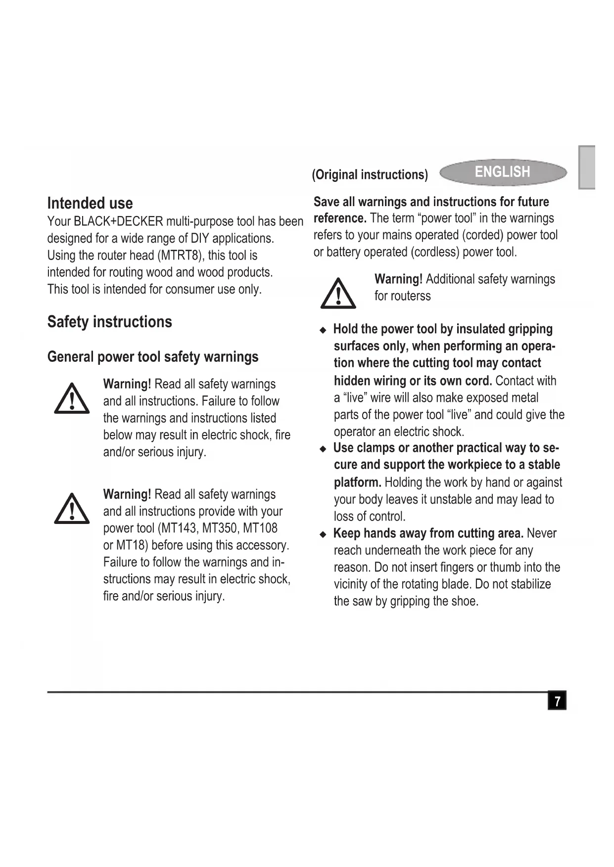
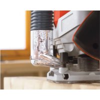
Your BLACK+DECKER multi-purpose tool has been designed for a wide range of DIY applications. Using the router head (MTRT8), this tool is intended for routing wood and wood products. This tool is intended for consumer use only.
Safety instructions
General power tool safety warnings

Warning! Read all safety warnings and all instructions. Failure to follow the warnings and instructions listed below may result in electric shock, fire and/or serious injury.

Warning! Read all safety warnings and all instructions provide with your power tool (MT143, MT350, MT108 or MT18) before using this accessory. Failure to follow the warnings and instructions may result in electric shock, fire and/or serious injury.
(Original instructions)
ENGLISH
Save all warnings and instructions for future reference. The term "power tool" in the warnings refers to your mains operated (corded) power tool or battery operated (cordless) power tool.

Warning! Additional safety warnings for routerss
Hold the power tool by insulated gripping surfaces only, when performing an operation where the cutting tool may contact hidden wiring or its own cord. Contact with a "live" wire will also make exposed metal parts of the power tool "live" and could give the operator an electric shock.
Use clamps or another practical way to secure and support the workpiece to a stable platform. Holding the work by hand or against your body leaves it unstable and may lead to loss of control.
Keep hands away from cutting area. Never reach underneath the work piece for any reason. Do not insert fingers or thumb into the vicinity of the rotating blade. Do not stabilize the saw by gripping the shoe.
ENGLISH
(Original instructions)
Keep blades sharp. Dull or damaged blades may cause the router to swerve or stall under pressure. Always use the appropriate type of router bit for the workpiece material and type of cut.
Do not touch the workpiece or the blade immediately after operating the tool. They can become very hot.
Be aware of hidden hazards, before cutting into walls, floors or ceilings, check for the location of wiring and pipes.
The blade will continue to move after releasing the switch. Always switch the tool off and wait for the router blade to come to a complete standstill before putting the tool down.

Warning! Contact with, or inhalation of dusts arising from cutting applications may endanger the health of the operator and possible bystanders. Wear a dust mask specifically designed for protection against dust and fumes and ensure that persons within or entering the work area are also protected.
Thoroughly remove all dust after routing.
Only use router bits with a shank diameter equal to the size of the collet installed in the tool.
Only use router bits suitable for the no-load speed of the tool.
Never use router bits with a diameter exceeding the maximum diameter specified in the technical data section.
Do not use the tool in an inverted position.
Do not attempt to use the tool in a stationary mode.
Take special care when routing where the paint is possibly lead based or when routing some woods which may produce toxic dust:
Do not let children or pregnant women enter the work area.
Do not eat, drink or smoke in the work area.
Dispose of dust particles and any other debris safely.
The intended use is described in this instruction manual. The use of any accessory or attachment or performance of any operation with this tool other than those recommended in this instruction manual may present a risk of personal injury and/or damage to property.
Features (fig. A)
This tool includes some or all of the following features.
- Router head
- Spindle lock button
- Lock off button
- Collet
- Chip deflector
- Dust Extraction adaptor
- Straight router bit
- Rounding over router bit
Assembly
Warning! Before assembly, remove the battery from the tool.
Fitting a router bit (fig. B)
Warning! Router bits are sharp,use care when handling them.
Note: This router is not reccomended for use with raised panel bits.
The router is equipped with a spindle lock feature that makes changing bits easy. Lock the spindle shaft by depressing the spindle lock button (11) as shown in figure B and use the supplied wrench to loosen (anti-clockwise) the collet (13).
(Original instructions)
ENGLISH
Keep the spindle lock button (11) depressed and rotate the spindle until the spindle lock fully engages.
Place the router upside down on a smooth, flat surface.
Loosen the collet (13) using the wrench provided. Insert the shank of the router bit into the collet (13).
When installing router bits, be sure they are inserted as far as possible and then pulled out about 1.5mm
Keep the spindle lock button (11) depressed and tighten the collet (13) clockwise (do not overtighten) using the wrench provided.
Note: If the router base is set at its maximum depth, the collet nut cannot be tightened properly. Always ensure that if the router base is adjusted to its maximum depth it must be backed off several rotations (counterclockwise) before tightening or loosening router bits. See "Setting the Routing Depth" below for router base adjustment.
Warning! Never tighten the collet without a router bit inserted. Tightening the collet without a router bit inserted may cause damage to the collet.
(Original instructions)
Setting the routing depth (fig. B)
Keep the spindle lock button (11) depressed and rotate the router base.
Rotating the base clockwise will increase the routing depth.
Rotating the base anti-clockwise will decrease the routing depth.
Two complete revolutions of the base is equal to about 2 millimeters in the change of depth.
After obtaining the desired routing depth, release the spindle lock button (11).
Continue turning the base until the notch under the spindle lock button aligns with the next closest locking slot.
Fitting the dust extraction adaptor (fig. D)
The dust extraction adaptor is used to connect a vacuum cleaner or dust extractor to the tool. Dust extraction must be used when cutting wood
Holding the router head (10) at a slight angle to the dust extraction adaptor (15), clip the router head (10) into the dust extraction adaptor (15). Ensure that the inner side (18) of the dust extraction adaptor (15) is inserted between two legs of the chip deflector (14)
Connect a vacuum cleaner hose by sliding it into the dust extraction outlet.
Use
Warning! Let the tool work at its own pace. Do not overload.
Warning! Do not touch work piece or router bit immediately after operating the tool. They can become very hot. Handle carefully. Always allow accessories and workpiece to cool before handling.
Note! This router is not recommended for metal cutting applications.
Note! This router is not recommended for plunge routing applications.
Switching on and off
Note: Ensure the forward reverse slider (2) is not in the locked position.
To switch the tool on, press in the lock off button (12) then press the variable speed switch (1). The tool should always be run at full speed.
Release the lock off button.
To switch the tool off, release the variable speed switch.
Routing (fig. E)
Make sure that the material to be cut is clamped down and is stable enough to support the router during operation.
Use both hands on the power unit to control the router, and run the router at full speed at all times.
Move the router counterclockwise when cutting outside edges. Move clockwise when cutting inside edges.
Hints for optimum use
When working on outside edges, move the tool counterclockwise (fig. E). When working on inside edges, move the tool clockwise.
Use pilot (ball bearing) router bits for edge profile cutting.
Use HSS router bits for softwood.
Use TCT router bits for hardwood.
Not recommended for plunge cutting.
Refer to the table below for common types of router bits.
(Original instructions)
ENGLISH
Router bits (fig. E)
| Description Application | |
| Straight bit (1) | Grooves and rebates |
| Trimming bit (2) | Trimming laminates or hardwood; accurate profiling using a template |
| Rebating bit (3) | Rebates on straight or curved workpieces |
| V-grooving bit (4) | Grooves, engraving and edge bevelling |
| Core box bit (5) | Fluting, engraving and decorative edge |
| moulding Cove bit (6) Decorative edge moulding | |
| Ogee moulding bit (7) Decorative edge moulding | |
| Rounding over bit (8) Rounding over edges | |
| Dovetail bit (9) Dovetail joints | |
| Chamfer bit (10) Chamfer edges | |
Accessories
The performance of your tool depends on the accessory used. BLACK+DECKER and Piranha accessories are engineered to high quality standards and designed to enhance the performance of your tool. By using these accessories you will get the very best from your tool.
Technical data
| MTRT8 (14.4V) (H1) | MTRT8 (Max) (H1) | ||
| No-load speed min | -1 | 0-9000 0-9000 | |
| Weight | kg 1.3 | 1.5 | |
| Collet size Inch | 1/4 1/4 | ||
| Collet size mm | 6.35 6.35 | ||
| Max dismeter of router bitt | mm | 25.4 25.4 | |
| Max. depth of cut mm | 25.4 25.4 |
| Level of sound pressure according to EN 60745: |
| Sound pressure (LpA) 78.3 dB(A), uncertainty (K) 3 dB(A) |
| Sound power (LWA) 89. dB(A), uncertainty (K) 3 dB(A) |
| Vibration total values (triax vector sum) according to EN 60745: |
| Vibration (ah) < 2.5 m/s2, uncertainty (K) 1.5 m/s2 |
Guarantee
Black & Decker is confident of the quality of its products and offers an outstanding guarantee. This guarantee statement is in addition to and in no way prejudices your statutory rights. The guarantee is valid within the territories of the Member States of the European Union and the European Free Trade Area.
If a Black & Decker product becomes defective due to faulty materials, workmanship or lack of conformity, within 24 months from the date of purchase, Black & Decker guarantees to replace defective parts, repair products subjected to fair wear and tear or replace such products to ensure minimum inconvenience to the customer unless:
The product has been used for trade, professional or hire purposes;
The product has been subjected to misuse or neglect;
The product has sustained damage through foreign objects, substances or accidents;
Repairs have been attempted by persons other than authorised repair agents or Black & Decker service staff.
To claim on the guarantee, you will need to submit proof of purchase to the seller or an authorised repair agent. You can check the location of your nearest authorised repair agent by contacting your local Black & Decker office at the address indicated in this manual. Alternatively, a list of authorised Black & Decker repair agents and full details of our after-sales service and contacts are available on the Internet at: www.2helpU.com
Please visit our website www.blackanddecker.co.uk to register your new BLACK+DECKER product and to be kept up to date on new products and special offers. Further information on the BLACK+ DECKER brand and our range of products is available at www.blackanddecker.co.uk
(Original instructions)
EC declaration of conformity MACHINERY DIRECTIVE

MTRT8
Black & Decker declares that these products described under "technical data" are in compliance with:
2006/42/EC, EN60745-1, EN60745-2-17
These products also comply with Directive 2014/30/EU and 2011/65/EU. For more information, please contact Black & Decker at the following address or refer to the back of the manual.
The undersigned is responsible for compilation of the technical file and makes this declaration on behalf of Black & Decker.

R. Laverick
Engineering Manager
Black & Decker Europe, 210 Bath Road, Slough,
Berkshire, SL1 3YD
United Kingdom
17/09/2014
DEUTSCH
Black & Decker Europe, 210 Bath Road, Slough,
Berkshire, SL1 3YD
Großbritannien
17/09/2014
FRANÇAIS
Responsible technique
Black & Decker Europe, 210 Bath Road, Slough,
Berkshire, SL1 3YD
Royaume-Uni
17/09/2014
ITALIANO
Black & Decker Europe, 210 Bath Road, Slough,
Berkshire, SL1 3YD
Verenigd Koninklijk
17/09/2014
ESPANOL
Black & Decker Europe, 210 Bath Road, Slough,
Berkshire, SL1 3YD
Storbritannien
17/09/2014
Bruksområde
Black & Decker Europe, 210 Bath Road, Slough,
Berkshire, SL1 3YD
Storbritannia
17/09/2014
DANSK
Black & Decker Europe, 210 Bath Road, Slough,
Berkshire, SL1 3YD
Storbritannien
17/09/2014
Käytötarkoitus
Black & Decker Europe, 210 Bath Road, Slough,
Berkshire, SL1 3YD
ToTtEtnon Tou TpOoapuoyea Eaywyns Okoyns (EK.D)
O ppoapuoyea c aaywyns kovns
xnoiopoioietai yia tn ouvdoon iaag nEeKtpiknC
ooutac n evoc aattaywooukovnc Tavw
To epyaieio. H attaywyn okovns npetie va
xnoiopoioietai kat a tv kontn gulou
KpatwtaTnV KepaHn Tns 0e Elaqpiia ywiA wS PPOs TOV PPOOAPoYea aTAYWyNc OKOvNc (15), aOpaIOTe Tnv KepaN TNS 0pEzac (10) oTov PPOOAPoYea aTAYWyns OKOvNc (15).BεbaIomegaEITE OTI n EOTePIKn PLEUPa (18) Tou PPOOAPoYea aTAYWyns OKOvNc (15) exi TOnTOEETnEi μEtaTuV Duo TIOWiV TOEKTPOITEA OXICWV (14)
u v e o t e to a nAekptpiKns OkoUTTaC oIAOaivovTac Tov OTnv E\xo0o E\xaywyns OKovns.
Xpñσ
PpOeIoOnoN! AqnoTe To EpyaIeio va IToupy^n i e To oikTou puOmu. Mny To UTEpOoTwVET.
PpOeIoOnoN! Mny ayyizTe to TPOc ETEpyaia avtkeiuevo n to akpo TnC φpeZac aEeowc tA th xphon tou epyaieou. Mtopei va evai Tlau Zeota. XepioTeite μe Tpooxh. AqnvTe TAVTa ta Tnpalekóeva kai To Teuaxio epyaioac va Kpuwoov TPIV TO xEIPIO.
Black & Decker Europe, 210 Bath Road, Slough,
Berkshire, SL1 3YD
Hvwévo Baoiλει
17/09/2014
| België/Belgique/LuxembourgStanley Black & Decker Belgium BVBA Tel. NL +32 15 47 37 65www.blackanddecker.be Egide Walschaertsstraat 16 Tel. FR +32 15 47 37 66enduser.be@sdbinc.com 2800 Mechelen Fax. +32 15 47 37 99 | |||
| Danmark Black & Decker kundeservice.dk@sdbinc.comRoskildevej 22 www.blackanddecker.dk2620 Albertslund | |||
| Deutschlandwww.blackanddecker.de Black & Decker Str. 40, D - 65510 Idstein infobfge@sdbinc.com | Stanley Black & Decker Deutschland GmbhFax 06126 21-2980 | 06126 21-0 | |
| Eλλάδαwww.blackanddecker.grgreece.service@sdbinc.com | Stanley Black & Decker (ΕλλΑΣ) E.I.EΓΑΦΕΙΑ:Στράβωνος 7 & Bouλιαγμένης166 74 Γλυφάδα - Αθήνα | Tηλ.210-8981616Φαξ210-8983570 | |
| SERVICE:193 00 Ασπρόπιργος - Αθήνα | Ημερος Τότος 2-Xάνι ΑδάμΦαξ 210-5597598 | Tηλ. Service210-8985208 | |
| Espanawww.blackanddecker.esrespuesta(posventa@sdbinc.com08820 El Prat de Llobregat (Barcelona) | Stanley Black & Decker Ibérica, S.C.A.Parc de Negocis "Mas Blau"Edificio Muntadas, c/Bergadá, 1, Of. A6 | Tel.934 797 400Fax934 797 419 | |
| Francewww.blackanddecker.frB.P. 3008469579 Limonest Cédex | Black & Decker (France) S.A.S.5 allée des Hétres Fax 04 72 20 39 00 | Tel.04 72 20 39 20 | |
| Helvetiawww.blackanddecker.chservice@rofoag.ch | ROFO AGGewerbezone Seeblick3213 Kleinbosingen | Tel.026-6749393Fax 026-6749394 | |
| Italiawww/blackanddecker.itservice.italia@sdbinc.com | Stanley Black & Decker ItaliaVia Energypark 620871 Vimercante (MB) | Tel.039-9590200Fax 039-9590313Numero verde 800-213935 | |
| Nederland Stanley Black & Decker Netherlands BV Tel. +31 164 283 065 www.blackanddecker.nl Holtum Noordweg 35, 6121 RE BORN Fax +31 164 283 200 enduser.nl@sbdinc.com Postbus 83, 6120 AB BORN | |||
| Norge Black & Decker kundeservice.no@sbdinc.com Postboks 4613, Nydalen www.blackanddecker.no 0405 Oslo | |||
| Österreich | Stanley Black & Decker Austria GmbH | Tel. | 01 66116-0 |
| www.blackanddecker.at service.austria@sbdinc.com | Oberlaaerstraße 248, A-1230 Wien | Fax | 01 66116-614 |
| Portugal | Black & Decker Limited SARL | Tel. | 214667500 |
| www.blackanddecker.pt resposta(posvenda@sbdinc.com 2770 - 071 Paço de Arcos | Quinta da Fonte - Edificio Q55 D. Diniz Rua dos Malhões, 2 e 2A - Piso 2 Esquerdo | Fax | 214667580 |
| Suomi PL47 00521, Helsinki | Black & Decker www.blackanddecker.fi | asiakaspalvelu.fi@sbdinc.com | |
| Sverige Box 94, 431 22 Mölndal | Black & Decker AB www.blackanddecker.se | kundservice.se@sbdinc.com | |
| Türkiye | KALE Hirdavat ve Makina AŞ. Defterdar Mah. Savaklar Cad. No:15 | Tel. | 0212 533 52 55 |
| www.blackanddecker.com.tr Edirnekapi / Eyüp / İstanbul 34050 | Fax. | 0212 533 10 05 | |
| United Kingdom & Republic Of Ireland | Black & Decker Tel. 01753 511234 | ||
| www.blackanddecker.co.uk emeaservice@sbdinc.com | 210 Bath Road Slough, Berkshire SL1 3YD | Fax | 01753 512365 |
| Middle East & Africa Black & Decker Tel. +971 4 8863030 www.blackanddecker.eae service.mea@sbdinc.com UAE | P.O.Box - 17164 Jebel Ali Free Zone (South), Dubai, Faz | +971 4 8863333 | |


- Safety instructions
- General power tool safety warnings
- (Original instructions)
- ENGLISH
- Features (fig. A)
- Assembly
- Fitting a router bit (fig. B)
- Setting the routing depth (fig. B)
- Fitting the dust extraction adaptor (fig. D)
- Use
- Switching on and off
- Routing (fig. E)
- Hints for optimum use
- Router bits (fig. E)
- Accessories
- Guarantee
- EC declaration of conformity MACHINERY DIRECTIVE
- DEUTSCH
- FRANÇAIS
- ITALIANO
- ESPANOL
- Bruksområde
- DANSK
- Käytötarkoitus
- ToTtEtnon Tou TpOoapuoyea Eaywyns Okoyns (EK.D)
- Xpñσ
Brand : BLACK & DECKER
Model : MTRT8
Category : Router