RP400 - Router BLACK & DECKER - Free user manual and instructions
Find the device manual for free RP400 BLACK & DECKER in PDF.
User questions about RP400 BLACK & DECKER
0 question about this device. Answer the ones you know or ask your own.
Ask a new question about this device
Download the instructions for your Router in PDF format for free! Find your manual RP400 - BLACK & DECKER and take your electronic device back in hand. On this page are published all the documents necessary for the use of your device. RP400 by BLACK & DECKER.
USER MANUAL RP400 BLACK & DECKER
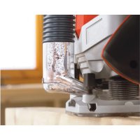
- Always use sharp bits and the appropriate accessory with this unit to prolong tool life and achieve desired cut quality.
- Whenever a router bit change is made remember to recalibrate the depth scale.
- Remember to lock the plunge release lever at the desired depth before cutting laterally on the work surface.
SAVE THIS MANUAL FOR FUTURE REFERENCE.
VEA EL ESPANOL EN LA CONTRAPORTADA.
INSTRUCTIVO DE OPERACION, CENTROS DE SERVICIO Y POLIZA DE GARANTIA. ADVERTENCIA: LEASE ESTE INSTRUCTIVO ANTES DE USAR EL PRODUCTO.
Form No. 394586-00 Cat. Nos. RP200, RP400 (JUL00-1) Copyright © 2000 Black & Decker Printed in China
GENERAL SAFETY RULES
WARNING: Read and understand all instructions. Failure to follow all instructions listed below may result in electric shock, fire and/or serious personal injury.
SAVE THESE INSTRUCTIONS
WORK AREA
- Keep your work area clean and well lit. Cluttered benches and dark areas invite accidents.
- Do not operate power tools in explosive atmospheres, such as in the presence of flammable liquids, gases, or dust. Power tools create sparks which may ignite the dust or fumes.
- Keep bystanders, children, and visitors away while operating a power tool. Distractions can cause you to lose control.
ELECTRICAL SAFETY
- Double insulated tools are equipped with a polarized plug (one blade is wider than the other.) This plug will fit in a polarized outlet only one way. If the plug does not fit fully in the outlet, reverse the plug. If it still does not fit, contact a qualified electrician to install a polarized outlet. Do not change the plug in any way. Double insulation eliminates the need for the three wire grounded power cord and grounded power supply system.
- Avoid body contact with grounded surfaces such as pipes, radiators, ranges and refrigerators. There is an increased risk of electric shock if your body is grounded.
- Don't expose power tools to rain or wet conditions. Water entering a power tool will increase the risk of electric shock.
- Do not abuse the cord. Never use the cord to carry the tools or pull the plug from an outlet. Keep cord away from heat, oil, sharp edges or moving parts. Replace damaged cords immediately. Damaged cords increase the risk of electric shock.
- When operating a power tool outside, use an outdoor extension cord marked "W-A" or "W." These cords are rated for outdoor use and reduce the risk of electric shock.
PERSONAL SAFETY
- Stay alert, watch what you are doing and use common sense when operating a power tool. Do not use tool while tired or under the influence of drugs, alcohol, or medication. A moment of inattention while operating power tools may result in serious personal injury.
- Dress properly. Do not wear loose clothing or jewelry. Contain long hair. Keep your hair, clothing, and gloves away from moving parts. Loose clothing, jewelry, or long hair can be caught in moving parts.
- Avoid accidental starting. Be sure switch is off before plugging in. Carrying tools with your finger on the switch or plugging in tools that have the switch on invites accidents.
- Remove adjusting keys or wrenches before turning the tool on. A wrench or key that is left attached to a rotating part of the tool may result in personal injury.
- Do not overreach. Keep proper footing and balance at all times. Proper footing and balance enables better control of the tool in unexpected situations.
- Use safety equipment. Always wear eye protection. Dust mask, non-skid safety shoes, hard hat, or hearing protection must be used for appropriate conditions.
TOOL USE AND CARE
- Use clamps or other practical way to secure and support the workpiece to a stable platform. Holding the work by hand or against your body is unstable and may lead to loss of control.
- Do not force tool. Use the correct tool for your application. The correct tool will do the job better and safer at the rate for which it is designed.
- Do not use tool if switch does not turn it on or off. Any tool that cannot be controlled with the switch is dangerous and must be repaired.
- Disconnect the plug from the power source before making any adjustments, changing accessories, or storing the tool. Such preventative safety measures reduce the risk of starting the tool accidentally.
- Store idle tools out of reach of children and other untrained persons. Tools are dangerous in the hands of untrained users.
-
Maintain tools with care. Keep cutting tools sharp and clean. Properly maintained tools, with sharp cutting edges are less likely to bind and are easier to control.
-
Check for misalignment or binding of moving parts, breakage of parts, and any other condition that may affect the tools operation. If damaged, have the tool serviced before using. Many accidents are caused by poorly maintained tools.
- Use only accessories that are recommended by the manufacturer for your model. Accessories that may be suitable for one tool, may become hazardous when used on another tool.
SERVICE
- Tool service must be performed only by qualified repair personnel. Service or maintenance performed by unqualified personnel could result in a risk of injury.
- When servicing a tool, use only identical replacement parts. Follow Instructions in the Maintenance section of this manual. Use of unauthorized parts or failure to follow Maintenance Instructions may create a risk of electric shock or injury.
SPECIFIC SAFETY RULES
- Hold tool by insulated gripping surfaces when performing an operation where the cutting tool may contact hidden wiring or its own cord. Contact with a "live" wire will make exposed metal parts of the tool "live" and shock the operator.
WARNING: Some dust created by power sanding, sawing, grinding, drilling, and other construction activities contains chemicals known to cause cancer, birth defects or other reproductive harm. Some examples of these chemicals are:
- lead from lead-based paints,
crystalline silica from bricks and cement and other masonry products, and
- arsenic and chromium from chemically-treated lumber (CCA).
Your risk from these exposures varies, depending on how often you do this type of work. To reduce your exposure to these chemicals: work in a well ventilated area, and work with approved safety equipment, such as those dust masks that are specially designed to filter out microscopic particles.
The label on your tool may include the following symbols.


Speed Control Knob Bouton de réglage de la vitessePerilla de controlde velocidad
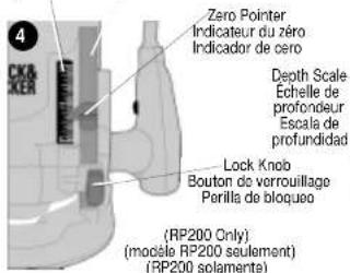
Zero Pointer
Indicator du zéro
Indicator de cero
Depth Adjustment Knob
Bouton de réglage de la
Perilla de ajuste de la profundidad

Dust extraction hose adaptor
Adaptateur de tube d'aspiration
Adaptador para la menquera de extracción de polvo.
Dust Extraction Port Office d'aspiration Conexion para la excidacion del
Trigger Lock Button
Bouton de verrouillage de la gacette
Beton del seguro del ganillo
Trigger Switch Interrupter à gachette Interrupter del galileo
- Disconnect plug from power supply before changing bits or making adjustments.
- Make sure collet nut is securely tightened to prevent router bit from slipping during use.
- Make sure switch is in the OFF position before plugging into power supply.
- Use both hands to hold router against the work.
- Wear safety glasses or eye shields when using the router.
MOTOR
Be sure the power supply agrees with nameplate marking. 120 Volts AC only means the tool will operate on standard 60Hz household power. Do not operate AC tools on DC. A rating of 120 volts AC/DC means that this tool will operate on standard 60Hz AC or DC power. This information is printed on the nameplate. Lower voltage will cause loss of power and can result in over-heating. All Black & Decker tools are factory-tested; if this tool does not operate, check the power supply.
USE OF EXTENSION CORDS
Make sure the extension cord is in good condition before using. Always use the proper size extension cords with the tool - that is, proper wire size for various lengths of cord and heavy enough to carry the current the tool will draw. Use of an undersized cord will cause a drop in line voltage resulting in loss of power and overheating. For proper size see the following chart.
| Minimum Gage for Cord Sets | |||||
| Volts Total Length of Cord in Feet | |||||
| 120V 0-25 26-50 51-100 101-150 | |||||
| 240V 0-50 51-100 101-200 201-300 | |||||
| Ampere Rating | |||||
| More Than | Not more Than | American Wire Gage | |||
| 0 - | 6 | 18 | 16 | 16 | 14 |
| 6 - | 10 | 18 | 16 | 14 | 12 |
| 10 - | 12 | 16 | 16 | 14 | 12 |
| 12 - | 16 | 14 | 12 | Not Recommended | |
Operating Instructions
BIT INSTALLATION AND REMOVAL
TURN OFF AND UNPLUG ROUTER NOTES:
-
ROUTER IS NOT RECOMMENDED FOR USE WITH RAISED PANEL
-
ROUTER IS NOT RECOMMENDED FOR USE IN METAL CUTTING APPLICATIONS.
-DO NOT USE ANY ROUTER BIT GREATER THAN 1-5/8" DIAMETER.
CAUTION: ROUTER BITS ARE SHARP, USE CARE WHEN HANDLING THEM.
INSTALLING BITS
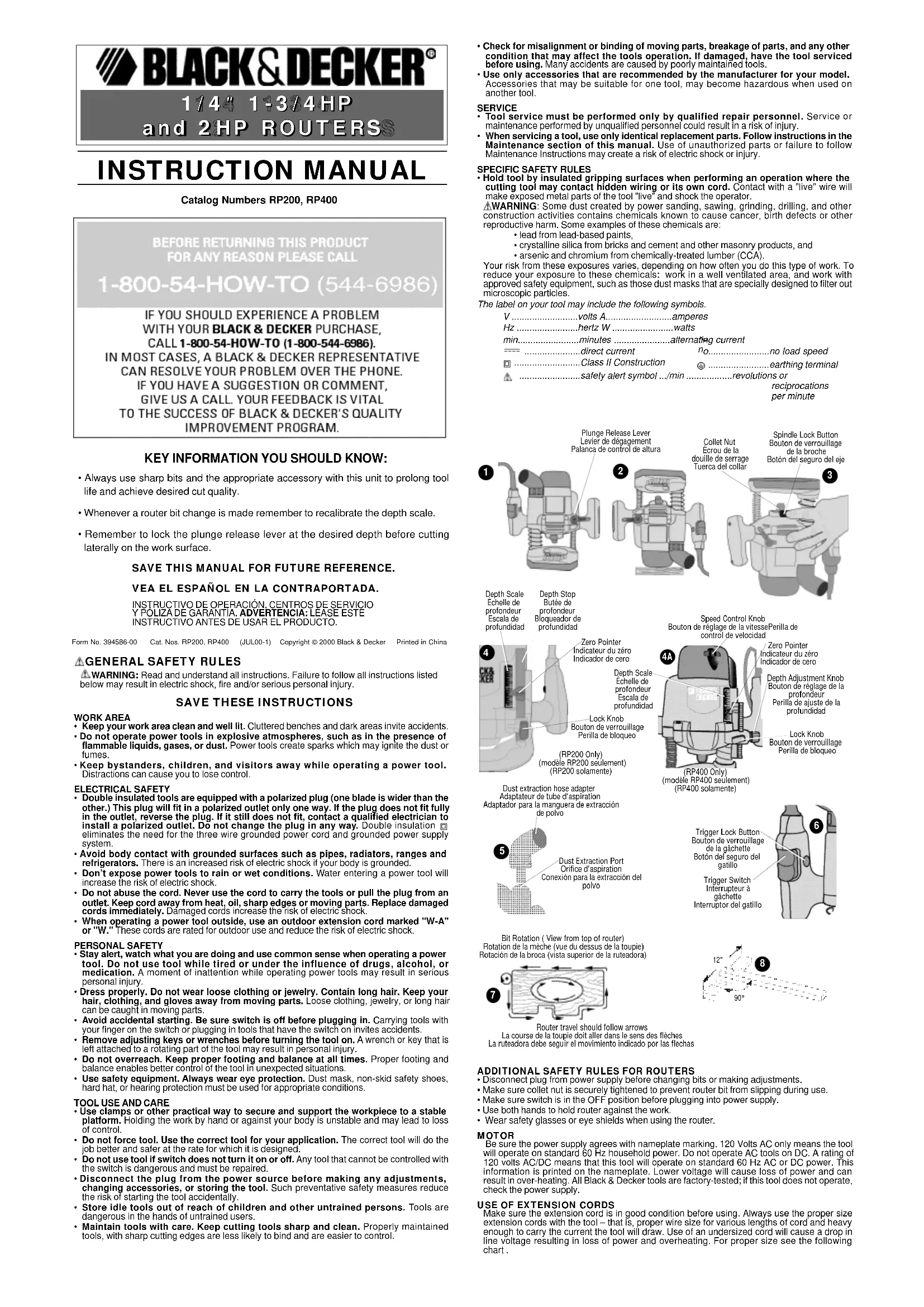
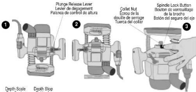
This router is equipped with a spindle lock feature that makes changing bits easy.
Loosen the plunge release lever (see figure 1) to release the router motor to its full height. Tighten the plunge release lever to lock the motor in place.
Place the router upside down on a smooth, flat surface. (See Figure 2.)
Hold the spindle shaft by depressing the spindle lock button as shown in Figure 3 and use the supplied wrench to loosen (counterclockwise) the collet nut. When installing router bits, be sure they are inserted as far as possible and then pulled out about 1/16" . Tighten collet nut firmly clockwise (do not over-tighten).
CAUTION: NEVER TIGHTEN COLLET NUT WITHOUT A 1/4" SHANK SIZE BIT INSERTED INTO COLLET. TO DO SO MAY BREAK OR DAMAGE COLLET. When finished, place the router right side up.
REMOVING BITS
CAUTION: Router bits get hot during use. Allow sufficient time for bit to cool before replacing.
Hold the spindle shaft by depressing the spindle lock button as shown in Figure 3 and use the supplied wrench to loosen (counterclockwise) the collet nut.
Controls
SETTING THE ROUTING DEPTH
TURN OFF AND UNPLUG ROUTER.
(MODEL RP200 ONLY)
Place the router (with the desired bit installed) on a smooth, flat surface.
-
Loosen the lock knob shown in Fig. 4 (counterclockwise) 1/4 of a turn. Lift depth stop as far as it will go. Tighten lock knob.
-
Losen the plunge release lever shown in Fig. 1 and push down on the router handles until the cutting edge of the bit touches the surface. Holding the router in this position, tighten the plunge release lever.
-
Loosen lock knob 1/4 turn. Lower the depth stop until it contacts the base. Tighten the lock knob.
-
Raise or lower the zero pointer (Fig. 4) as needed until the line meets up with the zero line on the scale.
-
Loosen lock knob 1/4 turn. Raise to increase the cutting depth stop as desired. Each mark on the calibrated depth scale represents 1 / 16 in routing. The zero pointer should now point to the depth of cut on the scale.
-
After setting the desired cutting depth, tighten the lock knob.
CAUTION: Firmly hold unit while loosening plunge release lever, as unit will spring back into full upright position.
(MODEL RP400 ONLY)
Place the router (with the desired bit installed) on a smooth, flat surface.
-
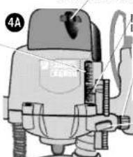
Loosen the lock knob shown in Fig. 4A (counterclockwise) 1/4 of a turn and rotate the depth adjustment knob also shown in Fig. 4 counterclockwise to raise the depth stop as far as it will go. Tighten the lock knob.
-
Loosen the plunge release lever shown in Fig. 1 and push down on the router handles until the cutting edge of the bit touches the surface. Holding the router in this position, tighten the plunge release lever.
-
Loosen the lock knob 1/4 turn and rotate the depth adjustment knob clockwise to lower the depth stop until it contacts the base.
-
Raise or lower the zero pointer (Fig. 4) as needed until the line meets up with the zero line on the scale.
-
Rotate the depth adjustment knob counterclockwise to increase the cutting depth as desired. Each mark on the calibrated depth scale represents 1/16 in routing. The zero pointer should now point to the depth of cut on the scale.
-
After setting the desired cutting depth, tighten the lock knob.
CAUTION: Firmly hold unit while releasing plunge release lever, as unit will spring back into full upright position.
ELECTRONIC SPEED CONTROL DIAL (MODEL RP400 ONLY)
The speed of this router is variable. Use the electronic speed control dial (Fig. 4A) to produce uniform cutting results in wood and plastics. Use the lower settings for large diameter cutters and the higher settings for small diameter cutters. See table below for more information.
SPEED SELECTION CHART
MATERIAL and the RECOMMENDED SPEED CHOICES
| Material | Cutter Diameter | Electronic Control Settings | ||||
| Dial #1 | Dial #2 | Dial #3 | Dial #4 | Dial #5 | ||
| Hardwood e.g. oak | Small (under-1/2") | - | O | XX | X | X |
| Medium (1/2" - 1-1/8") | O | X | XX | O | - | |
| Large (1-1/8" - 1-5/8") | XX | O | - | - | - | |
| Softwood e.g. pine | Small (under-1/2") | - | O | X | XX | XX |
| Medium (1/2" - 1-1/8") | O | X | XX | XX | XX | |
| Large (1-1/8" - 1-5/8") | XX | O | - | - | - | |
| Plastic-laminated chipboard | Small (under-1/2") | - | O | X | XX | XX |
| Medium (1/2" - 1-1/8") | O | X | XX | XX | XX | |
| Large (1-1/8" - 1-5/8") | XX | O | - | - | - | |
| Plastics | Small (under-1/2") | O | X | XX | XX | XX |
| Medium (1/2" - 1-1/8") | O | XX | X | X | X | |
| Large (1-1/8" - 1-5/8") | XX | O | - | - | - | |
This table can serve only as a guide, since wood is a living material. Even with the
same species of timber there will be large differences in hardness and density.
KEY: XXVERYGOOD X GOOD O SATISFACTORY -NOT RECOMMENDED
DUST COLLECTION AND EXTRACTION
To set the router for dust extraction:
- UNPLUG ROUTER FROM POWER SUPPLY.
- Slip the end of any standard vacuum cleaner tube onto hose adapter shown in Figure 5.
- When using dust extraction, be sure that the vacuum cleaner is out of the way and secure so that it will not tip over or interfere with the router or workpiece. The vacuum hose and power cord must also be positioned so that they don't interfere with the router or workpiece. If the vacuum cleaner or vacuum hose cannot be positioned properly, it should be removed.
- Turn on vacuum cleaner before router.
- Empty the vacuum cleaner as necessary.
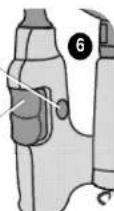
SWITCH
The switch is located in the router handle as shown in Figure 6. Depress the switch to turn the router on, release to turn it off. A lock button is provided (see Figure 6) to lock the switch on for continuous operation. To lock the switch on, squeeze the trigger and hold while you depress the lock button. Hold the button in while you release the trigger and the tool will continue to run. To turn the tool off, squeeze and release trigger.
USING THE ROUTER
- Make sure that the material to be cut is clamped down and is stable enough to support the router during operation.
- Use both hands on the handles to control the router.
- Move the router counterclockwise when cutting outside edges. Move clockwise when cutting inside edges. See Figure 7.
- Always hold router from the front insuring that the chip shield is between the user and the bit.
- After setting the cutting depth as described, locate the router such that the bit is directly over the place you will be cutting. With the router running, lower the unit smoothly down into the workpiece. (DO NOT FORCE THE ROUTER DOWN.) When the tool reaches the preset depth, tighten the plunge release lever. When you have finished routing, loosen the plunge release lever and let the spring lift the router directly out of the workpiece.
NOTE: Always feed the router opposite to the direction in which the cutter is rotating.
FEEDING SPEED AND RATE OF CUT
Variation between materials and bit configurations dictates a wide variety of feed rates. Experience is the best measure for determining feed rate. Become familiar with the sound and feel of the router by making practice cuts in scrap material.
The router bit rotates at a very high speed and may heat up if the router is moved too slowly through the wood and may cause burn marks. Feeding the router too fast or trying to remove too much material in a single pass will overload the motor. Use two or more passes for extra-large cuts (over 1/8" deep), especially in hard woods.
HELPFUL HINTS & RECOMMENDATIONS
Many types of novel and decorative edging can be easily accomplished with the router, using the wide variety of Black & Decker bits and accessories. Such cuts can be made directly along the edge of the work, such as table and desk tops, bookcase shelves, etc.
T-SQUARE GUIDE
A simple device for guiding the router when making straight cuts on flat surfaces is the homemade T-square, Figure 8. This T-square can be easily made out of scrap lumber, but make sure its edges are perfectly smooth and straight. It is placed on the surface being routed and held in position by means of a clamp. The metal flat portion of the base of the router is guided firmly along the edge of the T-square to make a straight cut. Measurements shown in Figure 8 are ideal for most applications with the router. They may, however, be altered to suit your specific needs.
STRAIGHT AND CIRCULAR GUIDE
A Straight and Circular Guide is available as an optional accessory. It enables the operator to make straight, curved or angular cuts with convenience and accuracy. For availability see "Accessories" section below.
MAINTENANCE
Use only mild soap and damp cloth to clean the tool. Never let any liquid get inside the tool; never immerse any part of the tool into a liquid.
IMPORTANT: To assure product SAFETY and RELIABILITY, repairs, maintenance and adjustment should be performed by authorized service centers or other qualified service organizations, always using identical replacement parts.
ACCESSIONS
Recommended accessories for use with this tool are available from your local dealer or authorized service center. If you need assistance regarding accessories, please call:
1-800-54-HOW-TO (544-6986).
WARNING: The use of any accessory not recommended for use with this tool could be hazardous.
SERVICE INFORMATION
Black & Decker offers a full network of company-owned and authorized service locations throughout North America. All Black & Decker Service Centers are staffed with trained personnel to provide customers with efficient and reliable power tool service.
Whether you need technical advice, repair or genuine factory replacement parts, contact the Black & Decker location nearest you. To find your local service location, refer to the yellow pages directory under "Tools-Electric" or call: 1-800-54-HOW-TO (544-6986).
FULL TWO-YEAR HOME USE WARRANTY
Black & Decker (U.S.) Inc. warrants this product for two years against any defects in material or workmanship. The defective product will be replaced or repaired at no charge in either of two ways.
The first, which will result in exchanges only, is to return the product to the retailer from whom it was purchased (provided that the store is a participating retailer). Returns should be made within the time period of the retailer's policy for exchanges (usually 30 to 90 days after the sale). Proof of purchase may be required. Please check with the retailer for their specific return policy regarding returns that are beyond the time set for exchanges.
The second option is to take or send the product (prepaid) to a Black & Decker owned or authorized Service Center for repair or replacement at our option. Proof of purchase may be required. Black & Decker owned and authorized Service Centers are listed under "Tools-Electric" in the yellow pages of the phone directory.
This warranty does not apply to accessories. This warranty gives you specific legal rights and
you may have other rights which vary from state to state. Should you have any questions, contact the manager of your nearest Black & Decker Service Center . This product is not
intended for commercial use.
Black & Decker (U.S.) Inc.,
701 E.Jcoppa Rd.
Towson, MD 21286 U.S.A.


GUIDE D'UTILISATION
Black & Decker Canada Inc. 100 Control Ave.
100 Central Ave. 12 (A) 13 (B)
BROxVill (Ontario) Rev 5w6