
RLM 4 - Robot mower Kärcher - Free user manual and instructions
Find the device manual for free RLM 4 Kärcher in PDF.



| Product type | Battery-powered robotic lawn mower |
| Brand | Kärcher |
| Model | RLM 4 |
| Maximum mowing area | 500 m² |
| Maximum slope | 45% (24°) |
| Cutting height | 25 to 55 mm (manually adjustable) |
| Battery type | Integrated lithium-ion battery (not user-removable) |
| Runtime | Approximately 60 minutes (depending on conditions) |
| Charging time | Approximately 60 minutes |
| Power supply | 100-240 V ~ 50/60 Hz power adapter |
| Length of perimeter wire included | 100 m |
| Programmable entry points | Up to 4 |
| Rain sensor | Yes, with adjustable sensitivity and delay |
| Lift and tilt sensor | Yes, automatically stops the blades |
| Theft protection | PIN code and PUK |
| Eco mode | Yes, reduces consumption and noise |
| Mowing program | Weekly scheduling, border mowing and secondary areas |
| Maintenance | Regular cleaning, replacement of cutting blades |
| Warranty | 2 years (according to legal requirements) |
Frequently Asked Questions - RLM 4 Kärcher
User questions about RLM 4 Kärcher
0 question about this device. Answer the ones you know or ask your own.
Ask a new question about this device
Download the instructions for your Robot mower in PDF format for free! Find your manual RLM 4 - Kärcher and take your electronic device back in hand. On this page are published all the documents necessary for the use of your device. RLM 4 by Kärcher.
USER MANUAL RLM 4 Kärcher
Typ 71364 Winnenden (Germany)
Winnenden, 2018/08/01
H. Jenner Chairman of the Board of Management
S. Reiser Director Regulatory Affairs & Certification
5 Start-up 52
5.1 Charging the rechargeable battery (08) 52 5.2 Making the basic settings 52 5.3 Setting the cutting height 52 5.4 Carrying out an automatic calibration movement 52
6 Operation 53
6.1 Starting the appliance manually 53 6.2 Cancelling mowing 53 6.3 Mowing the secondary area (01/NF) 53
7 Settings 53
7.1 Calling up the setting - General 53 7.2 Activating/deactivating the button tones 54 7.3 Activating/deactivating Eco mode 54 7.4 Setting the rain sensor 54 7.5 Setting the mowing program 54
7.5.1 Setting the mowing program - General 54 7.5.2 Setting entry points 54 7.5.3 Setting the mowing times 55
7.6 Edge mowing with a manual start 55 7.7 Setting the secondary area mowing 55 7.8 Setting the display contrast 56 7.9 Setting lock.. 56 7.10 Recalibrating 56 7.11 Restoring factory settings 56
8 Displaying information 56 9 Maintenance and care 56
9.1 Cleaning 57 9.2 Regular checks 57 9.3 Replacing the cutting blades 58
10 Transport 58 11 Storage 58
11.1 Storing the automatic lawnmower 58 11.2 Storing the charging station 59 11.3 Winter storage of the boundary cable 59
12 Disposal 59 13 Help in case of malfunction 61
13.1 Correcting appliance and handling faults 61 13.2 Fault codes and troubleshooting 62
14 Guarantee 66 15 EU declaration of conformity 66
1 ABOUT THESE OPERATING INSTRUCTIONS
The German version is the original operating instructions. All additional language versions are translations of the original operating instructions. It is essential to read through these operating instructions carefully before start-up. This is essential for safe working and trouble-free handling. Always safeguard these operating instructions so that they can be consulted if you need any information about the appliance. Only pass on the appliance to other persons together with these operating instructions. Comply with the safety and warning information in these operating instructions.
1.1 Legends and signal words

DANGER!
Denotes an imminently dangerous situation which will result in fatal or serious injury if not avoided.

WARNING!
Denotes a potentially dangerous situation which can result in fatal or serious injury if not avoided.

CAUTION!
Denotes a potentially dangerous situation which can result in minor or moderate injury if not avoided.
IMPORTANT!
Denotes a situation which can result in material damage if not avoided.

NOTE
Special instructions for ease of understanding and handling.
2 PRODUCT DESCRIPTION
This document describes a fully automatic, battery operated automatic lawnmower which moves freely on a grass surface. The cutting height can be adjusted.
2.1 Scope of supply
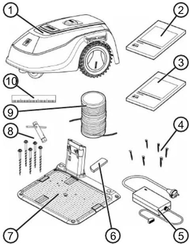
The items listed here are part of the scope of supply. Check that all items are included:
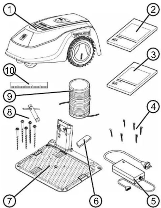
No. Component
1 Automatic mowers 2 Quickstart guide 3 Operating instructions 4 Lawn pegs (90 pcs.) 5 Power supply 6 Winter cover 7 Charging station 8 Grass screws (5 pcs.) with spanner 9 Boundary cable (100 m) 10 Cardboard ruler
2.2 Automatic mowers
Symbol Meaning
No. Component
| 1 Control panel with display (interior) |
| 2 STOP key (stops the appliance immediately and the cutting blade within 2 s) |
| 3 Charging contacts |
| 4 Height adjustment (interior) |
| 5 Front rollers (steering) |
| 6 Rechargeable battery compartment |
| 7 Mower deck |
| 8 Blade plate |
| 9 Drive wheel |
| 10 Fastening screw |
| 11 Clearer blade |
| 12 Cutting blade |
2.3 Symbols on the appliance
| Keep other people out of the danger area. |
| Pay special attention when handling this product. |
| Keep your hands and feet away from the blade system. |
| Maintain a safety distance. |
| Read the operating instructions before starting operation. |
| Enter the PIN in order to start the appliance. |
| Do not ride on the appliance. |
2.4 Control panel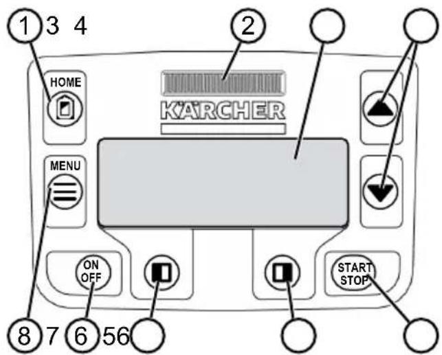
No. Component
| 1 | (home button): Cancel mowing, the appliance returns to the charging sta- tion. It starts on the next day automat- cally again at the set mowing time. |
| 2 Rain sensor: Registers if it rains (see chapter 7.4 "Setting the rain sensor", page 54). | |
| 3 Display: Shows the current operating status of the appliance, the name of the selected menu, its menu items and the functions to be selected. (see chapter 2.5 "Display", page 41). | |
| 4 | arrow keys): Select the menu items, increase and decrease numerical values, select between settings. |
| 5 | (Start/Stop button): Start mowing manually and stop mowing or immedi- agetly resume it again after pressing |
| 6 | function keys): Call up the func- tion that is displayed directly above the button on the display. |
| 7 | (On/Off button): Switch the appli- ance on and off. |
| 8 | (menu button): Call up the main menu. |
2.5 Display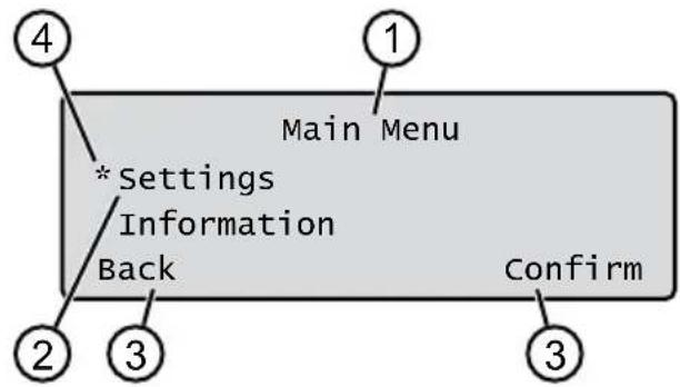
No. Display
| 1 Name of the selected menu (here: Main Menu) |
| 2 Menu items in the menu: Only two menu items are ever displayed (here: Settings and Information). Further menu items can be displayed with▲and▼ |
| 3 Functions for the selected menu item (here: Settings). Further functions can be called up with end. |
| 4 Asterisk for marking the displayed menu item (here: Settings) |
2.6 Menu structure
| Main Menu | Programs | Weekly Program see chapter 7.5 "Setting the mowing program", page 54 |
| Entry Point see chapter 7.5.2 "Setting entry points", page 54 | ||
| Program Info see chapter 8 "Displaying information", page 56 | ||
| Settings | Time see chapter 5.2 "Making the basic settings", page 52 | |
| Date see chapter 5.2 "Making the basic settings", page 52 | ||
| Language see chapter 5.2 "Making the basic settings", page 52 | ||
| PIN-Code see chapter 5.2 "Making the basic settings", page 52 | ||
| Key clicks see chapter 7.2 "Activating/deactivating the button tones", page 54 | ||
| EcoMode Activating/deactivating Eco mode | ||
| Rain sensor see chapter 7.4 "Setting the rain sensor", page 54 | ||
| After rain delay see chapter 7.4 "Setting the rain sensor", page 54 | ||
| Rain sensitive see chapter 7.4 "Setting the rain sensor", page 54 | ||
| Margin mowing see chapter 7.6 "Edge mowing with a manual start", page 55 | ||
| Sub zone active/disabled see chapter 7.7 "Setting the secondary area mowing", page 55 | ||
| Display contrast see chapter 7.8 "Setting the display contrast", page 56 | ||
| Safety settings see chapter 7.9 "Setting lock", page 56 | ||
| Reset calibration see chapter 7.10 "Recalibrating", page 56 | ||
| Factory reset see chapter 7.11 "Restoring factory settings", page 56 | ||
| Information | Blades service see chapter 8 "Displaying information", page 56 | |
| Hardware see chapter 8 "Displaying information", page 56 | ||
| Software see chapter 8 "Displaying information", page 56 | ||
| Program Info see chapter 8 "Displaying information", page 56 | ||
| Failures see chapter 8 "Displaying information", page 56 |
2.7 Charging station
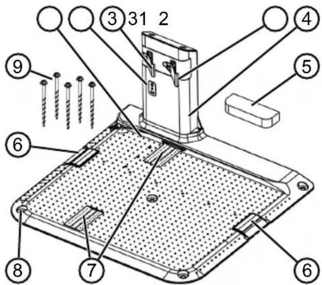
No. Component
1 Base plate 2 LEDs for status display 3 Charging contact 4 Charging station 5 Winter cover 6 Cable shaft 7 Wheel recess 8 Hole for grass screws (9) 9 Grass screws
2.8 Integrated battery
The battery is installed permanently in the appliance and may not be changed by the user.

NOTE
Fully charge the rechargeable battery before using it for the first time. The rechargeable battery can be charged in any charge status. Interrupting charging does not damage the rechargeable battery.
The rechargeable battery can only be charged after the appliance has been switched on.
The integrated battery is partially charged on delivery. The battery is regularly recharged during normal operation. The appliance returns to the charging station for this. The integrated electronic control unit with a monitoring function terminates the charging procedure when a 100% charge status is reached. The charging process only functions with perfect contact of the charging contacts on the charging station with the contact surfaces of the appliance. The built-in protection circuit prevents the battery from being charged at temperatures above 45°C. This prevents irreparable damage to the battery. If the operating time of the battery is reduced in spite of it being fully charged, have the battery replaced by a new genuine battery. This task should be carried out by a Karcher dealer, technician or service partner. If the battery charge level has dropped below the threshold set by the manufacturer as a result of ageing or excessively long storage, this means it can no longer be recharged. Have the battery and the monitoring electronic control unit checked by a Karcher dealer, technician or service partner, and replace them if necessary. The battery status is shown on the display. Check the battery status after about 3 months in storage. To do so, switch on the appliance and read off the battery status. If the rechargeable battery is now only charged to approx. 30% or less, place the appliance in the charging station and switch it on so the rechargeable battery is charged. If the charging pole was removed to store the charging station (see chapter 11.2 "Storing the charging station", page 59), first install it again in reverse order and connect the charging station to the mains supply again.
If electrolyte has escaped into the appliance: Have the appliance repaired by a Karcher service centre. If the rechargeable battery has been removed from the appliance: If the eyes or hands have come into contact with escaped electrolyte, flush them immediately with water. Immediately consult a doctor.
2.9 Functional description
Moving on the grass surface
The appliance moves freely in a mowing area delimited by a boundary cable. The appliance is oriented by sensors that detect the magnetic field of the boundary cable.
If the appliance encounters an obstacle, it stops and then continues in another direction. If the appliance detects moisture, it automatically returns to the charging station. If the appliance gets into a situation where it cannot operate, this is indicated by a message on the display.
Mowing and charging
The mowing phases alternate constantly with the charging phases. If the charge of the rechargeable battery drops to a specific value (display:
0%) during mowing, the appliance returns to the charging station along the boundary cable.
Pre-set mowing programs are available for mowing, and also include the lawn and edge mowing function. These mowing programs can be changed.
Each time the mowing motor is started, its direction of rotation is changed which doubles the service life of the cutting blades.
3 SAFETY
3.1 Intended use
This appliance is intended solely for use in non-commercial applications. Any other use (as well as unauthorised conversions or add-ons) are regarded as contrary to the intended use and will result in exclusion of the warranty as well as loss of conformity
(CE mark); the manufacturer will
thus decline any responsibility for damage and/or injury suffered by the user or third parties.
The application limits of the appliance are:
Max. area: 500 m² Max. upward/downward slope: 45% (24°) Max. lateral inclined angle: 45% (24°) Temperature:
Charging: 0 - 45°C Mowing: 0 - 55°C
3.2 Possible misuse
This machine is not suitable for use in public gardens, parks, sports stadiums, and in agriculture and forestry.
3.3 Safety and protective devices

WARNING!
Risk of injury
Defective and disabled safety and protective devices can lead to serious injury.
Have any defective safety and protective devices repaired. - Never disable safety and protective devices.
3.3.1 PIN and PUK input
The appliance can only be started by entering a PIN (Personal Identification Number). This prevents the appliance from being switched on by unauthorised persons. The factory setting of the PIN is 0000. The PIN can be changed, see chapter 5.2 "Making the basic settings", page 52.
If the PIN is entered incorrectly 3 times, the PUK (Personal Unlocking Key) must be entered. If this is also entered incorrectly, the user must wait 24 hours until entering it again.
The PIN and PUK input also serves as an anti-theft device:
- Keep the PIN and PUK so that they are inaccessible to unauthorised persons.
3.3.2 Sensors
The appliance is provided with several safety sensors. It does not restart automatically after being switched off by a safety sensor. The error message is shown on the display and must be acknowledged. The reason for the triggering of the sensor must be resolved.
Lifting sensor
If the appliance is raised by the housing during operation, the travel drive switches off and the cutting blades are stopped.
Bump sensors for obstacle detection
The appliance is equipped with sensors that ensure it changes its direction of travel if it encounters obstacles. When it encounters an obstacle, the top part of the deck is shifted slightly and the shock sensor is triggered.
Tilt sensor in direction of travel/sideways
If an upward or downward slope or a laterally inclined angle of 24° (45%) is reached in the direction of travel, the appliance is turned or the appliance changes its direction of travel.
Rain sensor
The appliance is equipped with a rain sensor that (when activated) interrupts the mowing procedure in case of rain, and ensures that the appliance returns to the charging station.

NOTE
The appliance can be operated reliably in the immediate vicinity of other automatic lawnmowers. The signal used in the boundary cable corresponds to the standard defined by the European Garden Machinery Industry Federation (EGMF) with regard to electromagnetic emissions.

3.4 Safety instructions
3.4.1 Operator
- Young people under 16 years of age, persons with limited physical, sensory or mental abilities or with a lack of experience and knowledge and persons who do not know the operating instructions must not use the device. Heed any country-specific safety regulations concerning the minimum age of the user.
- Do not operate the appliance if you are under the influence of alcohol, drugs or medication.
3.4.2 Personal protective equipment
Wear clothing and protective equipment in accordance with the regulations in order to avoid injury. The personal protective equipment comprises:
- Long trousers and sturdy shoes. During maintenance and care: Protective gloves.
3.4.3 Safety of persons and animals
In areas accessible to the public, affix warning information with the following content around the mowing area:

IMPORTANT!
Automatic lawn mower in operation!
Do not approach the appliance!
Supervise children.
Make sure that children and other persons are not present in the vicinity of the appliance when it is operating or climb onto the appliance and do not play with the appliance. - Sitting on the appliance and reaching into the cutting blade is forbidden. - Keep body and clothes away from the cutting unit.
3.4.4 Appliance safety
Before working, make sure that there are no objects (e.g. branches, glass or metal pieces, and items of clothing, stones, garden furniture, garden utensils or toys) in the work area of the appliance. They can damage the cutting blade of the appliance or can be damaged by the appliance.
Only use the appliance under the following conditions:
The appliance is not soiled. The appliance shows no damage or wear. All controls function properly. The charging station and power supply as well as their electrical supply cables are undamaged and function properly.
Always replace defective parts with original spare parts from the manufacturer. - Have the appliance repaired if it has been damaged. The user of the appliance is responsible for accidents of the appliance involving other persons or their property.
3.4.5 Electrical safety
- Never operate the appliance when a lawn sprinkler is operating on the mowing area at the same time.
- Do not spray the appliance with water.
- Do not open the appliance.
4 ASSEMBLY
4.1 Unpacking the machine
- Open the packaging carefully.
- Carefully remove all components from the packaging and check for transport damage. Note: If there is any transport damage, immediately notify your Karcher dealer, technician or service partner in accordance with the warranty conditions.
- Check the scope of supply, see chapter 2.1 "Scope of supply", page 39.
If the appliance is going to be sent on, retain the original packaging and accompanying documents. They will also be required for return shipment.
4.2 Planning the mowing areas (01)
Location of the charging station (01/1)
Shortest possible distance to the largest mowing area. Level surface. Protected against direct sunlight and harsh weather conditions. Connection option for power source. Free accessibility for the automatic lawn mower.
Routing the boundary cable (01)
The boundary cable must be laid in a continuous loop in a clockwise direction.
Corridors between mowing areas (01/h)
A corridor is a narrow section in the grass surface and can be used to connect two mowing areas.
Main area and secondary area(s) (01)
Main area (01/HF): This is the grass surface on which the charging station is located and whose entire surface can be mowed automatically by the appliance. Secondary area (01/NF): If a grass surface cannot be reached by the appliance from the main area, carry the appliance to the secondary area by hand if necessary. Secondary areas can be processed using manual operation.
The main area and secondary areas are bounded by the same continuous boundary cable, however.
Position of the entry points (01/X0 - 01/X3)
At the specified mowing time, the appliance moves along the boundary cable to the specified entry point and begins to mow there.
The entry points can be used to specify which areas of the mowing area are to be mowed several times.
4.3 Preparing the mowing areas
- Check that the grass surface is larger than the area covered by the appliance. If the grass surface is too large, an irregularly mown lawn will result. Reduce the size of the grass surface to be mowed if necessary.
- Before installation of the charging station and boundary cable or start-up of the appliance: Use a lawn mower to mow the grass surface to a low cutting height.
- Remove any obstacles on the grass surface or exclude them with the boundary cable (see chapter 4.5.3 "Excluding obstacles", page 50):
- Flat obstacles that will be run over and could damage the cutting blade (e.g. flat stones, transitions from the grass surface to the terrace or paths, plates, kerbs, stones, etc.) Holes and protrusions in the grass surface (e.g. molehills, burrowing holes, pine cones, fallen fruit, etc.)
- Steep ascents and descents of more than 45% (24°).
- Bodies of water (e.g., ponds, streams, swimming pools, etc.) and their demarcation from the grass surface. Shrubs and hedges that can become broader.
4.4 Setting up the charging station (03/a)
- Place the charging station (01/1) at right angles to the planned location of the boundary cable as described below:
Level (check with a spirit level). Straight and level entrance and exit. Not arched (the charging pole must not bend or tilt during subsequent tightening of the grass screws). When placed on a wall: a distance of at least 5 cm.
- Fix the charging station (03/2) to the floor with five grass screws (03/1).
4.5 Installing the boundary cable

NOTE
If the supplied boundary cable is too short, an extension cable can be obtained from your Kärcher dealer, technician, or service partner.
4.5.1 Connecting the boundary cable to the charging station (03/b)
- Pull the boundary cable (03/4) out of the packaging.
- Remove the cover of the cable shaft (03/3) on the connection (03/A).
- Insulate the end of the boundary cable (03/6) and insert it into the terminal (03/7).
- Close the terminal.
- Lead the boundary cable through the strain relief (03/5) out of the cable shaft with cable reserve.

NOTE
The cable reserve allows smaller corrections to be carried out on the cable guide later.
- Place the cover on the cable shaft.
4.5.2 Routing the boundary cable (01)
The boundary cable can be laid on the lawn and as much as 10 cm under the turf. Laying under the turf can be carried out by the dealer.
Both variants can be combined with one another.
IMPORTANT! Danger of damaging the boundary cable
If the boundary cable is damaged or cut, the transmission of the control signals to the appliance is no longer possible. In this case, the boundary cable must be repaired or replaced. The boundary cables are available from Kärcher.
Always route the boundary cable directly on the ground. If necessary, secure with an additional lawn peg. - When laying the boundary cable and during operation, protect the boundary cable from damage. - Do not dig or scarify in the vicinity of the boundary cable.
- Attach the boundary cable at regular intervals with lawn pegs or route it underground (at a max. depth of 10 cm).
- Route the boundary cable around obstacles: see chapter 4.5.3 "Excluding obstacles", page 50.
- Create corridors between individual mowing areas: see chapter 4.5.4 "Enclosing corridors (01/h)", page 50.
- Exclude excessive upward or downward slopes: see chapter 4.5.5 "Excluding downward slopes", page 50.
- Create loops of cable: see chapter 4.5.6 "Creating loops of cable (07)", page 50.
- After completing the routing of the boundary cable, connect to the connector (03/b) of the charging station: see chapter 4.5.1 "Connecting the boundary cable to the charging station (03/b)", page 49.
4.5.3 Excluding obstacles
Depending on the surroundings of the working area, the boundary cable must be routed at different distances to obstacles. Use the ruler that can be removed from the packaging to determine the correct distance.

NOTE
Exclusions are only necessary if they cannot be detected by the bump sensors of the appliance. Avoid too many or unnecessary exclusions.
Recesses that are smaller than 6 cm must be excluded, otherwise the appliance may cause damage.
Distance from walls, fences, beds: min. 20 cm (01)
The appliance moves along the boundary cable with an offset of 20 cm to the outside. Therefore, route the boundary cable at a distance of at least 20 cm from walls, fences, beds, etc.
Distance from terrace edges and paved paths (05)
If the terrace or path edge is higher than the grass surface, a distance of at least 20 cm must be complied with. If the edge of the terrace or path is at the same height as the grass surface, the cable can be routed exactly along the edge.
Distance of obstacles from the boundary cable (01)
If the boundary cables are precisely folded up away from the obstacle or towards the obstacle, i.e. distance 0 cm, the appliance moves beyond the boundary cable. Do not cross the boundary cables (02/c), but lay them parallel (01/e).
Routing the boundary cable around corners (06)
For inwards going corners (06/a): Route the boundary cable diagonally to avoid the appliance becoming caught in the corner. For outwards going corners with obstacles (06/b): Route the boundary cable in a point in order to avoid a collision of the appliance with the corner. For outwards going corners without obstacles: Route the boundary cable at an angle of 90°.
4.5.4 Enclosing corridors (01/h)
In the corridor the following distances must be complied with:
Total width: min. 60 cm Distance of the boundary cable to the edge: 20 cm Distance between the boundary cables: min. 30 cm
4.5.5 Excluding downward slopes
Downward slopes that are greater than 45% must be excluded with the boundary cable (45% = 45cm downward slopes per 1m horizontally).
4.5.6 Creating loops of cable (07)
Spare loops of cable should be incorporated at regular intervals in order to reposition the charging station or to extend the mowing area even after the mowing area has been laid out.
Select the number of spare cable loops according to your own judgement.

NOTE
In the case of spare cable loops, do not form open loops.
- Lead the boundary cable around the current lawn peg (07/1) and then back to the previous lawn peg (07/3).
- Then lead the boundary cable to the current lawn peg again. This creates a loop. The cables must be close together.
- If necessary, attach the loop to the ground in the middle with an additional lawn peg (07/2).
4.5.7 Typical faults in cable routing (02)
- Spare cable loops of the boundary cable are not laid in an even, elongated loop (02/a). The boundary cable is not routed properly around corners (02/b). The boundary cable is crossed over or not routed clockwise (02/c).
The boundary cable is routed too imprecisely so that edge areas of the grass surface cannot be mowed (02/d). The boundary cable is not routed lying directly next to itself when guided towards and back from the edge to an obstacle inside the lawn (02/e). The entry points are set too far away from the charging station (02/f). The boundary cable is routed beyond the edge of the grass surface (02/g). When routing the boundary cable, the minimum distance for corridors of 30 cm is undercut (02/h). The boundary cable is routed too close (i.e. at a distance of less than 20 cm) to obstacles that cannot be driven over (02/i).
4.6 Connecting the charging station to the power supply (04)
- Place the power supply (04/4) in a dry location that is protected against direct sunlight and sufficiently close to the charging station (04/1).
- Connect the low voltage cable of the power supply (04/5) and the cable of the charging station (04/6) with each other.
- Plug the power plug of the power supply (04/2) into a power socket (04/3).

NOTE
We recommend connecting the power supply to the mains supply via an earth leakage circuit breaker (ELCB) with a rated leakage current < 30 mA.
4.7 Checking the connections on the charging station (04)
- Check that both LEDs on the front side of the charging station (09/1) light. If not:
Disconnect the mains plug. - Check that all plug connectors of the power source and the boundary cable are positioned correctly and check for damage.
Status indications of the LEDs
LEDs Operating states
Green
Lights up when the boundary cable is laid correctly and the loop is intact. Flashes if a loop of the boundary cable is not in order.
LEDs Operating states
Yellow
Lights up if the power source is intact.
5 START-UP
This chapter describes the activities and settings that are necessary to put the appliance into operation for the first time. For all further settings, refer to chapter 7 "Settings", page 53.
5.1 Charging the rechargeable battery (08)
The integrated battery is partially charged on delivery. During normal operation, the battery of the appliance is regularly charged automatically.

NOTE
Fully charge the rechargeable battery before using it for the first time. The rechargeable battery can be charged in any charge status. Interrupting charging does not damage the rechargeable battery.
The rechargeable battery can only be charged after the appliance has been switched on.
- Place the appliance (08/1) in the charging station (08/3) so the contact surfaces of the appliance touch the charging contacts of the charging station.
- Switch on the appliance with ON OFF
- The display on the appliance shows "Battery is being recharged". If not: see chapter 13 "Help in case of malfunction", page 61.
5.2 Making the basic settings
- Open the cover flap.
- Switch on the appliance with ON OFF. The firmware, code number and type are displayed.
- In the menu for language selection, select the language with and accept with
- In the Login > Enter PIN menu, enter the preset PIN 0000. To do so, select the digit 0 with in sequence and always accept with After entering the PIN, access is enabled.
- In the Change PIN menu:
Under Enter new PIN, enter a self-selected new four-digit PIN. To do so, select one digit in sequence with and respectively confirm with Under Reenter new PIN, enter the new PIN again. If both entries are identical, PIN changed is displayed.
- In the Enter date menu, set the current date (format: DD.MM.20YY). To do so, select one digit in sequence with a respectively confirm with
- In the Enter time > HH:MM menu, set the current time (format: HH:MM). To do so, select one digit in sequence with respectively confirm with
The basic settings have been completed. The Not calibrated Press Start key status is displayed.
5.3 Setting the cutting height
The cutting height can be manually adjusted continuously between 25 - 55mm

NOTE
A cutting height of 55mm is recommended for the calibration movement (see see chapter 5.4 "Carrying out an automatic calibration movement", page 52) and for teaching the entry points (see see chapter 7.5.2 "Setting entry points", page 54).
- Open the cover (10/1).
- Set the cutting height (the current cutting height is displayed in the window (10/3) in millimetres):
- Increase the cutting height (i.e. lawn height): Turn the rotary knob (10/2) clockwise (10/+). Decrease the cutting height (i.e. lawn height): Turn the rotary knob (10/2) anticlockwise (10/-).
- Close the cover.
5.4 Carrying out an automatic calibration movement
Place the appliance at the starting position (09).
- Place the appliance at the starting position inside the mowing area:
At least 1 m left and 1 m in front of the charging station - Aligned with the front side to the boundary cable.
Starting the calibration movement
- Check that there are no obstacles in the expected movement area of the appliance. The appliance must be able to move over the boundary cable with both front wheels. Remove any obstacles if necessary.
- Start the appliance with START STOP. The following is shown on the display:
! Caution ! Starting Motors ■ Calibration, Phase [1]
During the calibration movement
To determine the signal strength inside the boundary cable, the appliance first moves twice straight beyond the boundary cable and then into the charging station and comes to a stop there.
The Calibration completed message is shown on the display. The rechargeable battery is being charged.

NOTE
The appliance must come to a stop when it moves into the charging station. If the appliance does not touch the contacts when it moves into the charging station, it moves further along the boundary cable. If the appliance moves through the charging station, the calibration procedure has failed. In this case, the charging station must be better aligned and the calibration procedure repeated.
After the calibration movement
The preset current mowing duration is displayed. For all further settings, refer to see chapter 7 "Settings", page 53.

NOTE
To ensure clean mowing, it is recommended to have the appliance measure the loop length. This is done with the teaching-in movement to determine the entry points (see chapter 7.5.2 "Setting entry points", page 54).
6 OPERATION
6.1 Starting the appliance manually
- Switch on the appliance with ON OFF. For unscheduled edge mowing: see chapter 7.6 "Edge mowing with a manual start", page 55.
- Start the appliance manually with START
6.2 Cancelling mowing
Press on the appliance. The appliance moves automatically into the charging station. It deletes the mowing plan of the current day and starts again the next day for the set time. Press START on the appliance. STOP The mowing is interrupted for half an hour. Press ON on the appliance. The appliance is switched off.

NOTE
In dangerous situations, the appliance can be stopped with the STOP button (08/2).
6.3 Mowing the secondary area (01/NF)
- Lift the appliance and place in the secondary area by hand.
- Switch on the appliance with ON OFF
- Call up the main menu with
- o* Settings
- o* zone mowing
- Select the mowing time with
- Start the appliance manually with
Depending on the setting: The appliance mows for the set time period and then switches off or mows until the rechargeable battery is flat.
After mowing the secondary area, place the appliance in the charging station again by hand.
7 SETTINGS
7.1 Calling up the setting - General
- Call up the main menu with Note: The asterisk * in front of the menu item indicates that it has just been selected.
- o* settings
- Select the required menu item with and accept with
- Make the settings.
Note: The menu items are described in the following sections.
- Return to the main menu with

NOTE
Further menu items: see chapter 5.2
"Making the basic settings", page 52.
7.2 Activating/deactivating the button tones
- clicks
- Activating/deactivating the button tones:
or activate:
Activate the button tones.
or reactivate:
Deactivate the button tones.
7.3 Activating/deactivating Eco mode
In Eco mode, the appliance switches to energy-saving mode. This reduces the energy consumption and noise emissions.

NOTE
With high and thick grass and for thick rolled turf, this is not recommended or may not be possible.
- on Mode
- Activating/deactivating Eco mode:
Activate
Activate Eco mode.
Deactivate
Deactivate Eco mode.
7.4 Setting the rain sensor

NOTE
Mowing when the grass is dry reduces soiling.
By activating the rain sensor and setting a delay time, it is possible to prevent the appliance from mowing when the grass is wet.
If the rain sensor is activated, the appliance moves back into the charging station when the rain begins. It remains there until the rain sensor has dried. Then it waits for the time period that is set as the delay before it continues mowing. The sensitivity of the rain sensor is adjustable.
- or Rn sensor
- Activating/deactivating the rain sensor:
orActivate:0
Activate the rain sensor.
or deactivate:
Deactivate the rain sensor.
- Setting the delay of the rain sensor:
or After rain delay
xx hours xx minutes Select the required value for the delay with or and accept with .
- Setting the sensitivity of the rain sensor:
or Rain sensitive
Select the required value for the sensitivity with a accept with
7.5 Setting the mowing program
7.5.1 Setting the mowing program - General
- Call up the main menu with
- o* Programs
- Select the menu item with an accept with
- Carry out the settings. Note: The menu items are described in the following sections.
7.5.2 Setting entry points
Learning entry points
- Place the appliance in the charging station.
- Switch on the appliance with ON OFF
- Call up the main menu with
- o* Programs
- Entry Point
- Interactive teach
- o* start interactive entry point teaching 0
Or start. The appliance moves along the boundary cable.
Or set when the appliance has reached the required entry point. The entry point is stored.
- Set entry point 1 if no entry point has been specified during the teaching-in movement. If no entry point has been specified here, the entry points are automatically specified.
- Entry point x: XX m if the last entry point has been reached.
Manually specifying entry points (01)
The first entry point (01/X0) is preset and is 1 m to the right of the charging station. Up to 3 other entry points (X1 to X3) can be programmed behind this point. When specifying the entry points, heed the following:
- Do not set entry points too far from the charging station or too close to one another (02/f). Only use as many entry points as necessary.
- Entry point
- Point x1 at [020m]
Select one digit in sequence with and always accept with
- Press x2 at [0.75m] Select one digit in sequence with and always accept with
- If necessary, specify further entry points.
- Return to the main menu with
7.5.3 Setting the mowing times

NOTE
There must be at least 30 min. between programming the mowing times and the mowing start. If not, the appliance only starts at the next programmed mowing time.
In the weekly Program menu item, the days of the week and time periods when the appliance should mow are set. Adapt these settings to the size of your garden if necessary. If unmown areas are still visible after approx. one week, increase the mowing periods.
- d* Weekly Program
or A11 Days [X]: The appliance mows every day at the set times. If A11 Days [] is shown, the appliance only mows on the set days of the week. or Monday [X]...* Sunday [X]: The appliance mows for the set time periods on the set day of the week. If Monday [ ] is shown, for example, the appliance does not mow on the respective day.
or change : Activate [X] or deactivate [] the respective day and set the time periods, type of mowing and the entry points.
- Make the settings for every day or the respective day:
e.g. [M] 07:00-10:00 [?] Normal mowing [M] from 7 am - 10 am with automatically changing entry point 0 - 3 [?] e.g. *[R] 16:00-18:00 [1]: The appliance starts with edge mowing [R] at 4 pm and moves along the entire boundary cable. The area mowing then begins at entry point 1 [1]. At 6 pm or as soon as the rechargeable battery is discharged, the appliance moves back to the charging station.
or change : Change the selected setting. or continue: confirm the changes setting and continue to the next setting.
- Save changed settings of the menu item.
7.6 Edge mowing with a manual start
For a manual start, the setting can be made here that the appliance begins with edge mowing. Carrying out the edge mowing at the programmed mowing time periods: see chapter 7.5.3 "Setting the mowing times", page 55.
- or * Margin mowing
- or* a manual start
7.7 Setting the secondary area mowing
- or zone mowing
- Setting the mowing time periods:
or inactive: Secondary area mowing is switched off. - or active : The appliance mows until the rechargeable battery is flat. or mowing time in min : The appliance mows the secondary area for the set time period. The following mowing time periods can be set: 15/30/until rechargeable battery flat.
7.8 Setting the display contrast
If the display is difficult to read, e.g. in sunlight, the display can be improved by changing the display contrast.
- o* display contrast
- Increase/decrease the display contrast with
or and accept with . 0
7.9 Setting lock
If the setting lock is deactivated, the PIN must only be entered when acknowledging safety-relevant faults.
- o* safety settings
- Activating/deactivating the setting lock:
or Activate: Activate the setting lock. or Deactivate: Deactivate the setting lock.
7.10 Recalibrating
If the position or length of the boundary cable has been changed or the appliance no longer finds the boundary cable, recalibration is necessary.
- Reset calibration
- Reset loop calibration data?
- Carrying out a calibration movement: see chapter 5.4 "Carrying out an automatic calibration movement", page 52.
7.11 Restoring factory settings
The factory settings of the appliance can be restored, e.g. before selling the appliance. 1. Factory reset. Appliance reports: Factory reset completed.
8 DISPLAYING INFORMATION
The Information menu is used for displaying machine data. No settings can be made in this menu.
- Call up the main menu with
- Information
- Select the menu item with and accept with. Note: The menu items are described in the following sections.
Return to the main menu with
Blades service
Shows in how many operating hours a blade service is required. The counter can be reset manually. Have the blade service carried out by a Karcher dealer, technician or service partner.
Reset the counter for blade service:
- Confirm
Hardware
Shows information on the appliance, such as type, year of manufacture, operating hours, serial identification number, number of mowing inserts, total mowing time, number of charging cycles, total charging time, length of the loop of the boundary cable.
Software
Shows the firmware version.
Program Info
Shows current settings such as the total weekly mowing time.
Failures
Shows the fault messages that last occurred with date, time and fault code.
9 MAINTENANCE AND CARE
CAUTION! Risk of injury
Sharp-edged and moving appliance parts can lead to injury.
Always wear protective gloves during maintenance, care and cleaning work.
9.1 Cleaning
IMPORTANT!
Danger from water
Water in the automatic lawnmower and in the charging station leads to damage to electrical components.
- Do not spray the automatic lawnmower and charging station with water.
Cleaning the automatic lawnmower

CAUTION!
Danger of injury due to the cutting blade
The cutting blades are very sharp and can cause cutting injuries.
Wear protective gloves. Make sure that parts of the body do not get into the cutting blade.
Once a week, carry out the following:
- Switch off the appliance with ON OFF.
- Wipe off the surface of the housing with a broom, a brush, a damp cloth or a fine sponge.
- Brush off the underside, mower deck and cutting blade with a brush.
- Check the cutting blade for damage. If necessary, replace it: see chapter 9.3 "Replacing the cutting blades", page 58.
Cleaning the charging station
- Regularly remove grass residues, leaves, or other objects from the charging station.
- Wipe off the surface of the charging station with a damp cloth or a fine sponge.
9.2 Regular checks
General checks
- Once a week, check the whole installation for damage:
Machine, charging station, boundary cable, power supply.
- Replace defective parts with original spare parts from Kärcher or have them replaced by a Kärcher service centre.
Check the rollers can move freely.
Once a week, carry out the following:
- Carefully remove grass residues and soiling from the areas around the rollers. Use a broom and cloth for this.
- Check that the rollers run freely and that they can be steered.
Note: If the rollers do not move freely or cannot be steered, have them replaced by a Kärcher service centre.
Check the contact surfaces on the automatic lawnmower.
- Use a cloth to remove soiling and then lightly grease with contact grease.
Check the charging contacts of the charging station
- Disconnect the mains plug.
- Press the charging contacts in the direction of the charging station and release them. The charging contacts must spring back into the initial position.
Note: If the charging contacts do not spring back, have them replaced by the Kärcher service centre.
9.3 Replacing the cutting blades

CAUTION! Danger of injury due to the cutting blade
The cutting blades are very sharp and can cause cutting injuries.
Wear protective gloves. Make sure that parts of the body do not get into the cutting blade.
IMPORTANT!
Damage to the appliance due to incorrect repair
The blade plate can be damaged by the alignment of a bent, built-in cutting blade.
- Do not align bent cutting blades.
- Replace bent cutting blades by original spare parts from Kärcher.
Worn or bent cutting blades must be replaced.
- Switch off the appliance with ON OFF.
- Put down the appliance with the cutting blades pointing upwards.
- Unscrew the fastening screws.
- Take the cutting blade out of the blade seat.
- Clean the blade seat with a soft brush.

NOTE
The cutting blades are sharpened along the entire length and can therefore also be mounted rotated by 180°, which doubles their runtime.
- Replacing the cutting blades:
If cutting blades have not been rotated since the initial mounting: Rotate the cutting blades by 180° and insert into the blade seat again with the sharpened side pointing towards the appliance, and tighten the fastening screws again by hand. If the cutting blades have already been rotated once since the initial mounting: Insert new cutting blades into the blade seat again with the sharpened side pointing towards the appliance, and tighten the new fastening screws by hand. Note: Only original spare parts from Karcher are allowed.
As a rule, the clearer blades do not need to be replaced.
In case of stubborn dirt that cannot be removed with a brush, the blade plate must be replaced because an imbalance can lead to increased noise levels, greater wear and malfunctions.
10 TRANSPORT
For transporting the appliance, e.g. from the main area to the secondary area, proceed as follows:
- Stop the appliance with START or the stop button.
- Switch off the appliance with ON OFF.
- Lift the appliance with both hands on the housing:
- Do not touch the cutting blades. The cutting blades must always point away from the body.
11 STORAGE
11.1 Storing the automatic lawnmower
The appliance must be stored over winter or when it is to be taken out of service for an expected duration of longer than 30 days.
- Fully charge the rechargeable battery (see chapter 5.1 "Charging the rechargeable battery (08)", page 52).
- Thoroughly clean the appliance (see chapter 9.1 "Cleaning", page 57).
- Store the appliance:
upright on all wheels at a dry, lockable location protected from frost out of the reach of children
11.2 Storing the charging station
The charging station can, but does not have to, be put into storage. Storage prevents premature ageing, however, such as fading of the colour or corrosion of the charging contacts.
If the charging station remains outdoors:
- Disconnect the power supply from the mains supply and unplug from the charging station.
- Roll up the cables of the charging station.
- Store the power supply.
- Grease the charging contacts with contact grease.
When the charging station is to be put into storage:
- Carry out all work mentioned above.
- Disconnect the charging station from the boundary cable.
- Remove the charging station and remove any soiling with a broom and a slightly damp cloth.
- Conserving the charging station:
at a dry, lockable location protected from frost out of the reach of children
If only the charging pole is stored:
- Disconnect the power supply from the mains supply and unplug from the charging station.
- Remove any soiling with a broom and a slightly damp cloth.
- Removing the charging pole:
Unscrew both screws of the charging pole (08/4). Remove the charging pole from the charging station by tilting. Undo the plug connection of the cables from the charging station and charging pole. Close the opening of the base (08/5) with the included winter cover (08/6).
- Storing the charging pole:
Store at a dry, lockable location protected from frost, out of the reach of children.
11.3 Winter storage of the boundary cable
The boundary cable can remain in the ground and does not need to be removed.
- When the charging station has been put into storage: Grease the cable ends with contact grease and wrap with adhesive tape. This protects the cable ends against corrosion.
12 DISPOSAL
Information on the German Electrical and Electronic Equipment Act (ElectroG)

- Electrical and electronic appliances do not belong in household waste, but should be collected and disposed of separately. Used batteries or rechargeable batteries that are not installed permanently in the old appliance must be removed before disposal. Their disposal is regulated by the battery law.
- Owners or users of electrical and electronic appliances are obliged by law to return them after use. The end user bears personal responsibility for deleting his personal data from the old appliance to be disposed of.
The symbol of the crossed-through rubbish bin means that electrical and electronic appliances may not be disposed of in the household rubbish. Electrical and electronic appliances can be handed in at the following places at no charge:
Public service disposal or collection points (e.g. municipal building yards) Points of sale of electrical appliances (stationary and online) provided traders are obliged to take them back or offer this voluntarily.
These statements only apply to appliances that are installed and sold in the countries of the European Union and are subject to European Directive 2012/19/EU. Different provisions may apply to the disposal of electrical and electronic appliances in countries outside the European Union.
Information on the German Battery Act (BattG)

Used batteries and rechargeable batteries do not belong in household waste, but should be collected and disposed of separately. For safe removal of batteries or rechargeable batteries from the electrical appliance and for information on their type or chemical system, follow the further information within the operating or installation instructions. Owners or users of batteries and rechargeable batteries are obliged by law to return them after use. Return is limited to the handover of customary household quantities.
Used batteries can contain harmful substances or heavy metals that can cause damage to the environment and human health. Reuse of the used batteries and use of the resources contained therein contributes to the protection of these two essential commodities.
The symbol of the crossed-through rubbish bin means that batteries and rechargeable batteries may not be disposed of in household rubbish.
In addition, if the symbol Hg, Cd or Pb appears under the rubbish bin, this stands for the following:
Hg: Battery contains more than 0.0005% mercury Cd: Battery contains more than 0.002% cadmium Pb: Battery contains more than 0.004% lead Rechargeable batteries and batteries can be handed in at the following places at no charge: Public service disposal or collection points (e.g. municipal building yards) Points of sale of batteries and rechargeable batteries Disposal points of the common take-back system for the used batteries of appliances Disposal point of the manufacturer (if not a member of the common take-back system)
These statements apply only to rechargeable batteries and batteries that are sold in the countries of the European Union and that are subject to European Directive 2006/66/EU. Different provisions can apply to the disposal of rechargeable batteries and batteries in countries outside the European Union.
Information on packaging

The packaging materials are recyclable. Please dispose of packaging in an environmentally friendly manner.
Remove the rechargeable battery before disposing of the appliance
The integrated rechargeable battery must be removed before disposal of the device and disposed of separately in an environmentally friendly manner.
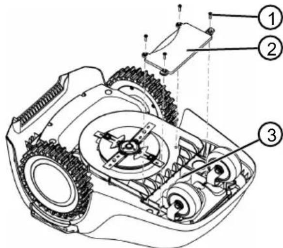
- Undo the screws (1).
- Take off the cover of the rechargeable battery compartment (2).
- Unplug the rechargeable battery (3) and take it out.
- Put the cover back on and fasten the screws.
13 HELP IN CASE OF MALFUNCTION
13.1 Correcting appliance and handling faults

CAUTION! Risk of injury
Sharp-edged and moving appliance parts can lead to injury.
Always wear protective gloves during maintenance, care and cleaning work.
| Malfunction Cause Remedy | ||
| The appliance does not start. | Rechargeable battery is flat. Charge the appliance in the charging station. | |
| The appliance gets stuck and has dug itself in. The wheels continue to turn. | Bump sensors do not trigger. Contact a Kärcher service centre. | |
| The grass is too high. | ■ Increase the cutting height, then lower in stages to the required height. ■ Mow the grass short with a lawn mower. | |
| The appliance sits on an unevenness of the grass surface. | Eliminate the unevenness. | |
| The appliance mows at the wrong time. | The appliance has the incorrect time. | Set the time. |
| Mowing times are incorrectly set. | Set the mowing times. | |
| The appliance loses the time settings. | The rechargeable battery is defective. Contact a Kärcher service centre. | |
| Motor stops during mowing. | Motor is overloaded. Switch off the appliance, set on level ground or shorter grass and restart. | |
| Rechargeable battery is flat. Charge the rechargeable battery. | ||
| The cutting blades are blunt. Turn over or replace cutting blades if necessary. | ||
| Mowing result is uneven. Mowing time is too short. Program longer mowing times. | ||
| Mowing area is too large. Reduce the mowing area. | ||
| Cutting height level is too low. | Increase the cutting height, then lower in stages to the required height. | |
| The cutting blades are blunt. Turn over or replace cutting blades if necessary. | ||
| Rechargeable battery oper-ating time is significantly shorter. | Cutting height level is too low. | Increase the cutting height, then lower in stages to the required height. |
| Grass is too long or too wet. | ■ Let the grass dry. ■ Set the cutting height to a higher level. | |
| Appliance vibrates or the volume is too high. | Imbalance on the cutting blade or in the cutting blade drive | Clean the mower deck.Contact a Kärcher service centre. |
| Rechargeable battery can-not be charged or low battery voltage | The charging contacts of the charging station are dirty.The contact surfaces on the appliance are soiled. | Clean the charging contacts and contact surfaces. |
| Charging station has no power. | Connecting the charging station to the power supply. | |
| The appliance does not touch the charging contacts.The contact surfaces on the appliance are burned out. | Place the appliance in the charging station and check that the charging contacts make contact.Contact a Kärcher service centre. | |
| The service life of the rechargeable battery has expired. | Contact a Kärcher service centre. | |
| The charging electronics are faulty. | Contact a Kärcher service centre. | |

NOTE
If you encounter any malfunctions that are not listed in this table or that you cannot rectify yourself, please contact our customer service.
13.2 Fault codes and troubleshooting
| Fault code Cause Remedy | |||
| CN001: Tilt sensor The inclination sensor has been triggered: ■ Max. tilt exceeded ■ The appliance has been carried ■ Slope too steep | Place the appliance on a flat surface and acknowledge fault. | ||
| CN002: Lift sensor The lift sensor has triggered: ■ The appliance cover has been deflected upwards by lifting or by an obstacle. | Remove the obstacle. | ||
| CN005: Bumper deflected | The appliance has driven in-to an obstacle and cannot free itself (e.g. collision close to the charging station). | ■ Place the appliance on the free, designated grass surface. ■ Correct the location of the boundary cable. | |
| Fault code Cause Remedy | |||
| CN007: No loop signal | ■ No loop signal ■ The boundary cable is faulty. ■ Loop signal is too weak. | ■ Check the LEDs on the charging station. ■ Check the power source of the charging station. Disconnect and re-connect the power supply. ■ Check the boundary cable for damage. Repair the defective cable. | |
| CN008: Loop signal weak | ■ Loop signal too weak ■ Boundary cable buried too deep | ■ Check the LEDs on the charging station. ■ Check the power source of the charging station. Disconnect and re-connect the power supply. ■ Raise the boundary cable to the prescribed height; attach directly on the grass if necessary. | |
| CN010: Bad position | ■ The appliance is outside the designated grass surface. ■ The boundary cable has been routed in a criss-cross pattern. | ■ Place the appliance on the free, designated grass surface. ■ Correct the location of the boundary cable around curves and obstacles. Eliminate the criss-crossing of the cable. | |
| CN011: Escaped robot | The appliance is outside the designated grass surface. | Correct the location of the boundary cable around curves and obstacles. | |
| CN012: Cal: no loop | Fault during the calibration: ■ The appliance cannot find the boundary cable. | ■ Check the LEDs on the charging station. | |
| CN015: Cal: outside | ■ Check the power source of the charging station. Disconnect and re-connect the power supply. ■ Place the appliance at the prescribed calibrating position; align precisely at right angles. Appliance must be able to drive over the boundary cable. | ||
| CN017: Cal: signal weak | Fault during the calibration: ■ Loop signal too weak ■ No loop signal ■ The boundary cable is faulty. | ■ Place the appliance at the prescribed calibrating position; align precisely at right angles. ■ Check the power source of the charging station. Disconnect and re-connect the power supply. ■ Check the boundary cable for damage. | |
| CN018: Cal: Colli-sion | Fault during the calibration: ■ The appliance has bumped into an obstacle. | Remove the obstacle. | |
| Fault code Cause Remedy | |||
| CN038: Battery The rechargeable battery is flat: | |||
| Loop of the boundary cable is too long, too many islands. | Correct the location of the boundary cable. | ||
| When charging, no contact to the charging contacts | Clean the charging contacts. Place the appliance in the charging station and check that the charging contacts make contact. Have the charging contacts checked and replaced by a Kärcher service centre. | ||
| Obstacles close to the charging station | Remove the obstacles. | ||
| The appliance has got stuck. | Place the appliance on the free, designated grass surface. | ||
| The appliance does not find the charging station. | Check the boundary cable for damage. Have the boundary cable measured by a Kärcher service centre. | ||
| The rechargeable battery is depleted. | Have the rechargeable battery replaced by a Kärcher service centre. | ||
| The charging electronics are faulty. | Have the charging electronics checked by a Kärcher service centre. | ||
| CN099: Recov escape | Automatic fault rectification not possible | Manually acknowledge the malfunction message. If the fault reoccurs: Have the appliance checked by a Kärcher service centre. | |
| CN104: Battery overheating | Rechargeable battery has overheated (more than 60 °C). No discharging is possible. Emergency switch-off by monitoring electronic control unit | Switch off the appliance and let the rechargeable battery cool down. Do not place the appliance on the charging station. | |
| CN110: Blade motor over heating | Mowing motor has overheated (more than 80 °C). | Switch off the appliance and let it cool down. If the fault reoccurs: Have the appliance checked by a Kärcher service centre. | |
| CN119: R-Bumper deflected | The appliance has moved onto an obstacle and cannot free itself. | Remove the obstacle. | |
| CN120: L-Bumper deflected | |||
| Fault code Cause Remedy | ||
| CN128: Recov Impos-sible | The appliance has moved onto an obstacle and cannot free itself. | Remove the obstacle. |
| The appliance is outside the designated grass surface. | ■ Place the appliance on the free, designated grass surface. ■ Correct the location of the boundary cable. | |
| CN129: Locked WL Left wheel motor is blocked. Remove blockage. | ||
| CN130: Locked WR Right wheel motor is blocked. | Remove blockage. | |

NOTE
For malfunctions that are not listed in this table or that you cannot resolve yourself, please contact our customer service.
14 GUARANTEE
We will resolve any material or manufacturing faults on the appliance during the legal warranty period for claims relating to faults, in accordance with our choice either to repair or replace. The legal warranty period is determined by the legislation of the country in which the appliance was purchased.
Our warranty promise applies only if:
These operating instructions are heeded The appliance is handled correctly Original spare parts have been used
The warranty becomes void in the case of:
Unauthorised repair attempts Unauthorised technical modifications Non-intended use
The guarantee excludes:
Paint damage that can be attributed to normal wear and tear
The guarantee period commences with purchase by the first end user. The date on the proof of purchase is decisive. In the event of a guarantee claim, please take this guarantee declaration and the original proof of purchase, and contact your dealer or the nearest authorised customer service centre. This statement does not affect the purchaser's statutory claims for defects against the vendor.
15 EU DECLARATION OF CONFORMITY
We hereby declare that the machine described below complies with the relevant basic safety and health requirements of the EU directives due to its design and construction as well as the version we have placed on the market. This declaration loses its validity if the machine has been modified without our consent.
Product
RLM4
Manufacturer
Alfred Karcher SE & Co. KG
Alfred-Karcher-Str.28-40
71364 Winnenden (Germany)
Tel.: +49 7195 14-0
Fax: +49 7195 14-2212
Authorised representative
S. Reiser
Type
RLM4
Relevant EU directives
2006/42/EC (+2009/127/EC)
2014/30/EU
2009/125/EC
2011/65/EU
2014/53/EU
Applied harmonised standards
EN 60335-1
EN 50636-2-107:2015
EN 61558-1
EN 61558-2-16
EN 62233:2008
EN 50563
EN 50581
The undersigned act on behalf of and with authority of the board.
Winnenden, 01/08/2018
H. Jenner
Chairman of the
Board of Management
S. Reiser
Director Regulatory Affairs & Certification
TRANSLATION OF THE ORIGINAL USER MANUAL
Table of contents
2 PRODUCT DESCRIPTION
- Activate/deactivate rain sensor:
or activate: Activate rain sensor.
Rain sensor deactivate.
8 DISPLAY INFORMATION
Winnenden, 2018/08/01
H. Jenner
Chairman of the Board of Management
S. Reiser
Director Regulatory Affairs & Certification
TRANSLATION OF THE ORIGINAL INSTRUCTIONS
Table of contents
71364 Winnenden (Germany)
2006/42/EC (+2009/127/EC)
2014/30/EU
2009/125/EC
2011/65/EU
2014/53/EU
Winnenden, 2018/08/01
H. Jenner
Chairman of the
Board of Management
S. Reiser
Director Regulatory
Affairs & Certification
TRANSLATION OF THE ORIGINAL INSTRUCTIONS FOR USE
Summary
71364 Winnenden (Germany)
Tel.: +49 7195 14-0
Fax: +49 7195 14-2212
2006/42/EC (+2009/127/EC)
2014/30/EU
2009/125/EC
2011/65/EU
2014/53/EU
Chairman of the Board of Management
S. Reiser
Director Regulatory Affairs & Certification
TRANSLATION OF THE ORIGINAL INSTRUCTION MANUAL
Index
2006/42/EC (+2009/127/EC)
2014/30/EU
2009/125/EC
2011/65/EU
2014/53/EU
Winnenden, 01/08/2018
H. Jenner
Chairman of the Board of Management
S. Reiser
Director Regulatory Affairs & Certification
TRANSLATION OF ORIGINAL INSTRUCTIONS FOR USE
Contents
1 About these instructions for use 197
71364 Winnenden (Germany)
Tel.: +49 7195 14-0
RLM4
Fax: +49 7195 14-2212
2006/42/EC (+2009/127/EC)
2014/30/EU
2009/125/EC
2011/65/EU
2014/53/EU
Person authorized for documentation
S. Reiser
Winnenden, 2018/08/01

H. Jenner
Chairman of the
Board of Management
S. Reiser
Director Regulatory
Affairs & Certification
TRANSLATION OF THE ORIGINAL INSTRUCTIONS FOR USE
Contents
1 About these operating instructions 227
1.1 Explanation of symbols and signal words 227
2 Product description 228
2.1 Scope of delivery 228 2.2 Robotic mower 228 2.3 Symbols on the device 229 2.4 Control panel 229 2.5 Display 230 2.6 Menu structure 231 2.7 Charging station 232 2.8 Integrated battery 232 2.9 Function description 232
3 Safety 233
3.1 Intended use 233 3.2 Possible misuse 233 3.3 Safety and protective devices 233
3.3.1 PIN and PUK entry 233 3.3.2 Sensors 234
!Caution ! Starting Motors ■ Calibration, Phase [1]
- or * Weekly Program
or A11 Days [X]: The device mows every day at the set times. If A11 Days [ ] is displayed, the device only mows on the set days of the week. or Monday [X]...* Sun-day [X]: The device mows on the set day of the week at the set times. If, for example, Monday [ ] is displayed, the device does not mow on that day. or change: Activate [X] or deactivate [ ] the corresponding day, set the times, mowing mode, and starting points.
- or * Margin mowing
- or * manual start
7.7 Setting mowing of adjacent areas
- or * zone mowing
- Setting mowing times:
or inactive: Mowing of adjacent areas is switched off. or active: The device mows until the battery is discharged. or mowing time in min
The device mows the adjacent area for the set duration. You can set the following mowing times: 15/30/until the battery is discharged.
7.8 Setting the display contrast
If the display is difficult to read (e.g., in direct sunlight), the display can be improved by adjusting the contrast.


contrast.

Increase/decrease the con-
trast of the display and confirm with the button.
7.9 Protection of settings
If the settings protection is deactivated, a PIN must only be entered when confirming a safety-related error.



settings

2006/42/EC (+2009/127/EC)
2014/30/EU
2009/125/EC
2011/65/EU
2014/53/EU
Harmonized standards used
EN 60335-1
EN 50636-2-107:2015
EN 61558-1
EN 61558-2-16
EN 62233:2008
EN 50563
EN 50581
Winnenden, 01/08/2018
H. Jenner Chairman of the Board of Management
S. Reiser Director Regulatory Affairs & Certification
TRANSLATION OF ORIGINAL INSTRUCTIONS
Table of contents
!Caution ! Starting Motors ■ Calibration, Phase [1]
During calibration drive
- at Every Point
- Point x1 at [020m]
- Point x2 at [075m]
Relevant EU directives
2006/42/EC (+2009/127/EC)
2014/30/EU
2009/125/EC
2011/65/EU
2014/53/EU
Person responsible for compiling the technical documentation
S. Reiser
Chairman of the Board of Management
S. Reiser
Director Regulatory Affairs & Certification
Translation of the original operating instructions
Table of contents
Winnenden, 2018/08/01
H. Jenner Chairman of the Board of Management
S. Reiser Director Regulatory Affairs & Certification
TRANSLATION OF THE ORIGINAL INSTRUCTIONS FOR USE
Table of contents
Type 71364 Winnenden (Germany) Tel: +49.7195.14-0
RLM4 Fax: +49 7195 14-2212
Applicable EU Directives
2006/42/EC (+2009/127/EC)
2014/30/EU
2009/125/EC
2011/65/EU
2014/53/EU
Winnenden, 2018/08/01
H. Jenner
Chairman of the Board of Management
S. Reiser
Director Regulatory Affairs & Certification
Translation of the original instructions
CN005: Bumper deflected
CN007: No loop signal
Missing loop signal. The boundary wire is defective. The loop signal is too weak.
71364 Winnenden (Germany)
RLM4
Tel.: +49 7195 14-0
Fax: +49 7195 14-2212
Applicable EC directives
2006/42/EC (+2009/127/EC)
2014/30/EU
2009/125/EC
2011/65/EU
2014/53/EU
Authorized for documentation
S. Reiser
Applied harmonized standards
EN 60335-1
EN 50636-2-107:2015
EN 61558-1
EN 61558-2-16
EN 62233:2008
EN 50563
EN 50581
Winnenden, 2018/08/01
H. Jenner Chairman of the Board of Management
S. Reiser Director Regulatory Affairs & Certification
TRANSLATION OF THE ORIGINAL OPERATING MANUAL
Table of contents
1 OPERATING MANUAL 378
1.1 Symbols and signal words 378
2 Product description 378
2.1 Scope of delivery 379 2.2 Gas detector operation 379 2.3 Symbol display 380 2.4 Control panel 380 2.5 Display 381 2.6 Menu structure 382 2.7 Charging station 383 2.8 Built-in battery 383 2.9 Functional description 384
3 Safety 384
3.1 Intended use 384 3.2 Improper use 384 3.3 Protective devices 385
3.3.1 PIN and PUK code entry 385 3.3.2 Lanyard 385
3.4 Safety instructions for the technician 386
3.4.1 Operator 386 3.4.2 Personal protective equipment 387 3.4.3 Safety for animals 387 3.4.4 Device safety 387 3.4.5 Electrical safety 388
4 Installation 388
4.1 Device layout 388 4.2 Scan area plan (01) 388 4.3 Preparing the scan area 388 4.4 Installing the charging station (03/a) 389 4.5 Installing the limiting cable 389
4.5.1 Connecting the limiting cable to the charging station (03/b) 389 4.5.2 Laying the limiting cable (01) 389 4.5.3 Insulating the joints 390 4.5.4 Narrowing the passages (01/h) 391 4.5.5 Excluding slopes 391 4.5.6 Laying cable reserves (07) 391 4.5.7 Typical errors when laying the cable (02) 391
4.6 Connecting the charging station to the power supply (04) 391 4.7 Checking the connections of the charging station (04) 392
5 Commissioning 392
5.1 Charging the battery (08) 392 5.2 Setting the basic settings 392 5.3 Adjusting the cutting height 393 5.4 Performing automatic calibration 393
6 Control 393
6.1 Starting the device manually 393 6.2 Canceling work in scan mode 394 6.3 Scanning an additional area (01/NF) 394
7 Settings 394
7.1 Calling up settings - general 394 7.2 Enabling/disabling key press signals 394 7.3 Enabling/disabling ECO mode 394 7.4 Setting the rain sensor 395 7.5 Setting the scan program 395
7.5.1 Setting the scan program - general 395 7.5.2 Setting entry points 395 7.5.3 Setting scan times 396
7.6 Scanning edges with manual start 396 7.7 Setting the scanning of an additional area 396 7.8 Setting the contrast of the display 396 7.9 Protecting settings 397 7.10 Recalibration 397 7.11 Restoring factory settings 397
8 Information 397 9 Maintenance and care 397
9.1 Cleaning 398 9.2 Regular tests 398 9.3 Replacing the blade 399
10 Transport 400 11 Storage 400
11.1 Storing the robotic lawn mower 400 11.2 Storing the charging station 400 11.3 Storing the connection cable for the charging station 401
12 Disposal 401 13 Troubleshooting 403
13.1 Correcting device and processing errors 403 13.2 Error codes and troubleshooting 404
14 Warranty 408 15 EU Declaration of Conformity 408
1 INFORMATION ABOUT THE OPERATING MANUAL
The German version is the original operating manual. All other language versions are translations of the original operating manual. You must read this operating manual before putting the device into operation. This is necessary for safe and reliable operation. Always keep this operating manual at hand so that you can read it if you need information about the device. Pass the device on to other persons only together with this operating manual. Read and follow the safety instructions and warnings contained in this operating manual.
1.1 Basic Symbols and Signal Words

DANGER!
Indicates a hazardous situation which, if not avoided, will result in death or serious injury.

WARNING!
Indicates a potentially hazardous situation which, if not avoided, could result in death or serious injury.

CAUTION!
Indicates a potentially hazardous situation which, if not avoided, may result in minor or moderate injury.
NOTICE!
Indicates a situation which, if not avoided, may result in property damage.

NOTE
Special instructions for easier understanding and operation.
2 PRODUCT DESCRIPTION
This document describes a fully automatic battery-powered lawn mower that moves freely on the lawn. The cutting height is adjustable.
2.1 Scope of Delivery
The scope of delivery includes the listed items. Check that all items are present:
The battery is installed in the device and cannot be replaced by the user.

NOTE
Before first use, the battery must be fully charged. The battery can be charged at any charge level. Interrupting the charging process does not damage the battery.
The battery can only be charged when the device is switched on.
The built-in battery is included in the scope of delivery. During normal operation, the battery is charged regularly. For this purpose, the device is placed on the charging station. The built-in electronic monitoring system automatically stops the charging process when a 100% charge level is reached. The charging process only works if the charging contacts of the charging station are in perfect contact with the contact surfaces of the device. At temperatures above 45°C, the built-in protection circuit prevents the battery from being charged. This prevents the battery from being destroyed. If the battery runtime decreases significantly despite proper charging, the battery must be replaced by a specialist, technician, or the Karcher service partner with a new original battery. If the battery is discharged beyond the manufacturer's specifications due to aging or prolonged storage, it cannot be recharged. Have the battery and the electronic monitoring system checked by a specialist, technician, or the Karcher service partner and replace it if necessary. The battery status is displayed on the display. Check the battery status after 3 months of storage. To do this, switch on the device and read the battery status. If the battery is charged to approximately 30% or less, place the device on the charging station and switch it on to charge the battery. If the charging station was dismantled for storage (see Chapter 11.2 "Storage of the charging station", page 400), install it in reverse order and connect it to the mains again.
If the battery in the device is leaking: Contact the Karcher service center for repair! If the battery has been removed from the device and as a result electrolyte has leaked and come into contact with exposed skin or eyes: Rinse immediately with water and seek medical attention promptly!
2.9 Description of functioning
Behavior on the lawn
The device moves freely within the mowing area, which is defined by the boundary wire. The orientation of the device is carried out with the help of sensors that detect the magnetic field of the boundary wire.
If the device encounters an obstacle, it stops and continues moving in a different direction. If the device detects moisture, it automatically returns to the charging station. If the device gets into a situation where operation is not possible, a message appears on the display.
Working time, mowing time, charging
The mowing stages change constantly according to the charging stages. If the battery charge reaches a certain value during mowing (e.g., 0%), the device returns to the charging station along the boundary wire.
Preset mowing programs are provided for the mowing mode, which also include the function for mowing edges. These mowing programs can be changed.
The direction of rotation of the drive mechanism changes, which increases the service life of the blades.
3 SAFETY
3.1 Intended use
This device is intended for private use. Any other use or unauthorized modifications or additions are not permitted.
Intended use and lead to voiding of the warranty, as well as loss of conformity (CE mark) and rejection of any liability for damage caused to the user or third parties by the manufacturer. Operating limits:
Maximum area: 500 m² Maximum slope/grade: 45% (24°) Maximum lateral slope: 45% (24°) Temperature:
Loading: 0-45°C Storage: 0-55°C
3.2 Improper use
This device is not suitable for use in parks, gardens, sports fields, as well as in agriculture and forestry.
3.3 Safety devices

WARNING!
Risk of injury
Malfunction or operation without protective and safety devices can cause injuries.
Defective protective and safety devices must be repaired. Never disable protective and safety devices.
3.3.1 Entering the PIN code and PUK code
The device can only be started by entering the PIN code (Personal Identification Number). This prevents it from being switched on by unauthorized persons. The factory setting of the PIN code is 0000. The PIN code can be changed, see Chapter 5.2 "Setting Basic Settings", page 392.
If the PIN code is entered incorrectly 3 times, the PUK code (Personal Unblocking Key) must be entered. If it is also
entered incorrectly, you must wait 24 hours before the next entry.
The PIN code and PUK code are also used for theft protection:
- Keep the PIN code and PUK code out of reach of unauthorized persons.
3.3.2 Sensors
The device is equipped with several safety system sensors. It is not automatically restarted after switching off via a safety system sensor. An error message is displayed on the display and must be confirmed. The cause of the sensor triggering must be eliminated.
Lift sensor
If the device is lifted from the housing during operation, the drive of the lifting mechanism is switched off and the knives stop.
Do not lean against the device!
Watch your step!
During operation, make sure that children are not near the device or on the device and do not play with the device. It is forbidden to sit on the device and touch the knife!
5.4 Performing automatic calibration
Setting the initial position of the device (09)
- Place the device in the scanning area in the initial position:
The charging station must be aligned with the limiting cable.
Starting calibration
- First, remove any obstacles in the path of the device. The device must be able to drive both front wheels over the limiting cable. If necessary, remove obstacles.
2. Start the device using (START) on the display as shown:
!Attention! Start drive calibration, Phase
During calibration
To determine the signal level in the limiting cable, the device first passes twice directly over the limiting cable, then moves to the charging station and stops there.
On the display, calibration is complete. Battery is charged.

NOTE
When approaching the charging station, the device must stop. If the device does not make contact with the charging station contacts, it will continue moving along the limiting cable. If the device moves past the charging station, the calibration process is not performed. In this case, the charging station must be properly aligned and the calibration process repeated.
After calibration
The current cutting time is displayed.
For all other settings, see Chapter 7 "Settings", page 394.

NOTE
To ensure clean cutting, it is recommended that the device measures the loop length. This is done during the learning time to determine the entry points (see Chapter 7.5.2 "Setting entry points", page 395).
6 CONTROL
6.1 Starting the device manually
- Turn the device on using ON/OFF
For unplanned scanning of edges: see section 7.6 "Scanning edges with manual start", page 396.
- Start the device manually using STOP
6.2 Canceling work in scanning mode
Press the device.
The device then automatically returns to the charging station. It deletes the scan plan for the current day and restarts the next day at the set time.
Press START on the device. STOP
The scanning operation is interrupted for 30 minutes.
Press ON on the device.
To turn off.

NOTE
In dangerous situations, the device can be stopped using the STOP button (08/2).
6.3 Scanning additional area (01/NF)
1. Lift the device and place it on the additional surface. 2. Turn on the device using ON/OFF. 3. Call up the main menu using 4. Set the settings 5. Start scanning
additional surface
- Select the scan time using
AUNI
- Start the device inside using STOP
Depending on the settings: the device performs scanning at the set time, then switches off or continues scanning until the battery is discharged.
After scanning, place the device back in the charging station.
7 SETTINGS
7.1 Calling up settings - general
- Call up the main menu using . Note: The asterisk * before a menu item indicates that this menu item is currently selected.
- settings
- Select the desired menu item using or confirm with . 4. Set the settings. Note: The menu functions are described in the following sections.
- Return to the main menu using

NOTE
For menu items, see section 5.2 "Setting the main settings", page 392.
7.2 Enabling/disabling signals by pressing buttons
- wA * zuk klavishej 0
- Enabling/disabling signals by pressing buttons:
To enable:
Enable signals by pressing the button.
To disable: 0
Disable signals by pressing the button.
7.3 Enabling/disabling ECO mode
In ECO mode, the device switches to an energy-saving mode. This reduces power consumption and noise level.

NOTE
It is not recommended and impossible in case of high density grass, as well as dense artificial turf.
- w A * FVMode
- Enabling/disabling ECO mode:
Set to 0 to disable the ECO switch. Deactivate the ECO switch.
7.4 Installing the Rain Sensor

NOTE
Mowing wet grass increases contamination.
By installing the rain sensor, a delay time can be set to prevent mowing wet grass with the device.
When the rain sensor is activated, the device returns to the charging station when it rains. It stays there until the rain sensor dries out. Then it waits for the set delay time before continuing normal mowing. The sensitivity of the rain sensor is adjustable.
- n * s o r dozhdya 2. Enable/Disable the Rain Sensor:
NIN
'pustit':
0
Enable the rain sensor.
HNN
eakt.: ①
1
Disable the rain sensor.
3. Setting the rain sensor delay:
HNN
Rain delay
xx hours xx minutes
Select the desired delay value using the buttons and confirm with the button
4. Setting the rain sensor sensitivity:
HNN
Sensor sensitivity
0
Set the desired sensitivity value using the buttons and confirm with the button
7.5 Setting the scanning program
7.5.1 Setting the scanning program - general
Call up the main menu using
- w * Rgrammy 3. Select the menu item using the buttons and confirm with the button 4. Set the settings. Note: The menu items are described in the following sections.
- Select the menu item using 1 and confirm with 4. Set the settings. Note: The menu functions are described in the following sections.
7.5.2 Setting Entry Points
Learning Entry Points
- Place the device in the charging station. 2. Turn on the device using ON/OFF
- Call up the main menu using
- w * Rprogram
- w * Start item
- n* path definition
- v* start of familiarization ride through start points
Start. The device moves within the limited cable range. Use the device to reach the desired entry point. The entry point is saved.
- Repeat start point 1 if the entry point was not set during the learning ride. If the entry point is set, the entry points are set automatically.
- Start point x: XXm, when the last entry point was reached.
Setting entry points manually (01)
The input terminal (01/X0) is located 1 m to the right of the charging station. Up to three additional input terminals (from X1 to X3) can be programmed via this terminal. When installing input terminals, note the following:
Do not install input terminals too far from the charging station or too close to each other (02/f). Use only as many input terminals as necessary.
- Point X1 at [020m]: enter the value using the buttons and confirm with the button.
- Point X2 at [075m]: enter the value using the buttons and confirm with the button.
4. If necessary, set further input points. 5. Return to the main menu using the button.
7.5.3 Setting the scanning time

NOTE
Between programming the scanning time and the scanning cycle, the interval must be at least 30 minutes. Otherwise, the device will not start at the next programmed scanning time.
The menu item "Programma nedeli" is used to set the days and scanning times of the device. If necessary, set these settings according to the size of the garden. If you still see unprocessed areas after about a week, increase the scanning time.
All days [X]: The device performs scanning every day at the set time. If "All days [ ]" is displayed, the device will only perform scanning on the set days of the week. Monday [X]...Sunday [X]: The device performs scanning on the selected days of the week. For example, if Monday [ ] is displayed, the device will not perform scanning on that day. To change: activate [X] or deactivate [ ] for the corresponding day, set the time, and the scanning input points.
- Setting the settings for all days or for one day:
Example: *[M]07:00-10:00[?]: Normal scanning [M] from 07:00 to 10:00 with automatic change of input point 0-3[?]. For example, *[R]16:00-18:00[1]: The device starts at 16:00 in edge scanning mode [R] and moves along the entire organizing cable. After that, scanning of the area begins with input point 1 [1]. At 18:00, as soon as the battery is discharged, the device returns to the charging station.
Change: Select the selected setting. Confirm: Confirm the changed setting. Next: Go to the next.
- Save: Save all changed settings of the menu item.
7.6 Edge scanning with manual start
For manual start, you can set here the start of the device's operation with edge scanning.
Edge scanning according to the programmed scanning time: see Table 7.5.3 "Setting the scanning time", p. 396.
- Edge scanning 0
- manual start
7.7 Setting scanning of an additional area
- Additional area scanning 2. Setting the scanning time:
Active: Scanning of the additional area is enabled. The device performs scanning until the battery is fully discharged. Or set the scanning time in min. The device scans the additional area for the specified time. You can set such a scanning time: 15/30 / until the battery is discharged.
7.8 Setting the display contrast
If the display, for example, in case of sunlight, is poorly readable, the indication can be improved by changing the display contrast.
- Display contrast
- Increase/Decrease the display contrast.
7.9 Settings protection
If settings protection is disabled, the PIN code only needs to be entered in case of an error related to security.
- Settings protection
- Enabling/disabling settings protection:
Enable: enabling settings protection. Disable: disabling settings protection.
7.10 Recalibration
If the method for the limit cable has been changed or if the device can no longer detect the limit cable, recalibration is required.
- Recalibration
- Return to previous state?
- Performing calibration: see Chapter 5.4 "Performing automatic calibration", p. 393.
7.11 Restoring factory settings
The device's factory settings can be restored, for example, before selling.
- Factory settings Device notification: Settings successfully restored
8 VIEWING INFORMATION
This menu displays information about the device. In this menu, you can set the settings.
- Call up the main menu using
- w * Information
- Select the menu item using
Confirm with D. The menu items are described in the following paragraphs.
- Return to the main menu using .
Blade service
Displays the hours of operation that are required for blade maintenance. The counter can be reset manually. Have the blade serviced by a specialist, technician, or Karcher service partner.
Reset the blade service counter:
- Confirm
Hardware
Displays information about the device, such as: type, year of manufacture, hours of operation, serial number, number of blades in the set, total mowing time, number of charging cycles, total charging time, length of the limiting cable.
Software
Displays the version of the microcontroller program.
Program Info
Displays current settings such as general timeouts and delays.
Faults
Displays the latest messages about errors with codes, date, time, and error code.
9 MAINTENANCE AND CARE

CAUTION! Risk of injury
Moving parts and parts with sharp edges can cause injuries.
Always wear protective gloves during maintenance, care, and cleaning!
9.1 Cleaning
ATTENTION!
Do not spray the robotic lawn mower or the charging station with water.
Cleaning the robotic lawn mower

CAUTION!
Risk of injury from the blade
The blade is very sharp and can cause injuries.
Wear protective gloves! Make sure that the blade does not come into contact with the blade.
Perform this once a week:
- Switch off the device using ON/OFF. 2. Wipe the housing surface with a soft, damp cloth or a soft brush.
- Clean the blade, blade guard, and blade bolt with a soft brush.
- Check the blade for damage. Replace if necessary: see Chapter 9.3 "Replacing the blade", page 399.
Cleaning the charging station
- Regularly remove grass, leaves, and other objects from the charging station.
- Clean the surface of the charging station with a damp cloth or a soft brush.
9.2 Regular inspections
General inspections
- Check the entire installation once a week for damage:
Charging station device, limiting cable, power supply unit
- Replace defective parts with original spare parts from Kärcher or have them replaced by the Kärcher service center.
Checking the free movement of the rollers
Perform once a week:
- Carefully clean the areas around the rollers of grass and dirt. Use a brush or cloth. 2. Make sure that the rollers move and turn freely.
Note: If the contact points are moved or cannot be controlled, have them replaced by the Karcher Service Center.
Checking the contact surfaces on the robot mower
- Clean off dirt with a cloth and lightly grease with a consistent grease.
Checking the charging contacts on the charging station
- Remove the plug.
- Press and release the charging contacts in the direction of the charging station. The charging contacts must return to their original position.
Note: If the charging contacts do not return, have them replaced by the Karcher Service Center.

CAUTION!
Risk of injury from cuts caused by the blade
The blade is very sharp and can cause injuries.
Wear protective gloves! Make sure that all body parts do not come into contact with the blade.
ATTENTION!
Damage to the device due to incorrect repair
Straightening a bent built-in blade can damage the blade edge.
Do not straighten a bent blade edge. Replace a bent blade edge with original Karcher spare parts.
The blades of the device must be replaced.
- Switch off the device using ON OFF.
- Place the device with the blades facing up.
- Unscrew the mounting screws.
- Remove the blade from the cutting tool.
- Clean the cutting tool with a soft brush.

NOTE
The blade is sharpened on both sides, so it can be installed at a 180° angle, which doubles the service life.
6. Replacing the blade:
If the blade has not been used after the first assembly: turn the blade 180° and insert it into the cutting tool with the sharpened side facing the device, then tighten the mounting screws by hand. If the blade has been used after the first assembly: insert a new blade with the sharpened side facing the device into the cutting tool and tighten the new mounting screws.
Note: Only original Karcher spare parts may be used.
The blade does not need to be sharpened. In case of heavy contamination that cannot be removed with a brush, the blade must be replaced, as imbalance can lead to increased noise, higher wear, and malfunction.
10 TRANSPORT
When transporting the device, for example, from the main area to the secondary area:
- Stop the device using STOP or the stop button.
- Turn the device on/off using the ON/OFF button. 3. Press the device on both sides of the housing:
Avoid contact with the knife. Always avoid contact of the knife with body parts.
11 STORAGE
11.1 Storing the robotic lawn mower
Store the device for the winter period if it will not be used for more than 30 days.
- Fully charge the battery (see Chapter 5.1 "Charging the battery," page 392).
- Clean the device thoroughly (see Chapter 9.1 "Cleaning," page 398).
- Storing the device:
Store on all wheels in a dry, cool, and frost-protected place, out of reach of children.
11.2 Storing the charging station
The charging station can be stored, but it is not necessary. However, storage prevents premature aging, for example, fading of paint, corrosion of charging contacts.
If the charging station remains outdoors:
- Disconnect the alternating current adapter from the charging station.
- Disconnect the charging station from the limiting cable.
- Send the power supply unit for storage. 4. Lubricate the charging contacts with consistent grease.
Storage of the charging station:
- Perform all the above-mentioned work.
- Disconnect the charging station from the limiting cable.
- Remove the charging station and clean the dirt with a soft, slightly damp cloth.
4. Storage of the charging station:
In a dry, locked, and frost-protected place, out of the reach of children.
For storage of the charging column only:
- Disconnect the AC adapter from the charging station's power supply.
- Remove dirt with a brush and a slightly damp cloth.
- Remove the charging column:
Unscrew both screws of the charging station (08/4). Release the charging column, tilting it away from the charging station. Disconnect the cable connections from the charging station and the charging column. Close the opening in the base (08/5) with the supplied radiator cap (08/6).
4. Storage of the charging column:
In a dry, locked, and frost-protected place, out of the reach of children.
11.3 Storage of the limiting cable in winter period
The limiting cable can remain in the ground and does not need to be removed.
- Charging station: Lubricate the cable ends with consistent grease and wrap them with insulating tape. This protects the cable ends from corrosion.
12 DISPOSAL
Information according to the law on electrical and electronic equipment

Electrical and electronic equipment must not be disposed of as household waste. It must be collected and disposed of separately! Used batteries and accumulators must be removed from the old device before disposal! Their disposal is regulated by the battery law. Owners or users of electrical and electronic equipment are obliged to return the device after use in accordance with the law. The end user is responsible for deleting their personal data from the used equipment that is subject to disposal!
The symbol of the crossed-out waste container indicates that electrical and electronic equipment must not be disposed of together with household waste.
Electrical and electronic equipment can be handed in free of charge at the following locations:
Public disposal service or collection points (e.g., municipal depots) and electrical equipment retailers (stationary or online stores), provided that the sellers are obliged to accept the equipment or offer return on a voluntary basis.
These regulations apply only to devices installed and sold in countries of the European Union, in accordance with EU Directive 2012/19/EC. In countries outside the European Union, other rules regarding the disposal of electrical and electronic devices may apply.
Information according to the battery law

Used batteries and accumulators must not be disposed of as household waste. They must be collected and disposed of separately! To safely remove batteries or accumulators from an electrical device, as well as to obtain information about their type or chemical system, see the supplementary information in the operating instructions or installation manual. Owners or users of batteries or accumulators are obliged to return the device after use in accordance with the law. The return is limited to the quantity of purchased or disposed items for household use.
Used batteries may contain harmful substances or heavy metals that can harm the environment and health. The proper recycling of used batteries and the use of resources contained in them contributes to the protection of these two important assets.
The symbol of the crossed-out waste container indicates that batteries and accumulators must not be disposed of together with household waste.
In addition, the symbols Hg, Cd, or Pb are placed under the waste container symbol. This means the following:
Hg: Battery contains more than 0.0005% mercury. Cd: Battery contains more than 0.002% cadmium. Pb: Battery contains more than 0.004% lead.
Batteries can be disposed of free of charge at the following locations:
State disposal agency or collection points (e.g., municipal depots), battery and accumulator shops, collection points for the joint return system of used batteries and devices, and manufacturer collection points (if the manufacturer is not part of the joint return system).
These regulations apply only to accumulators and batteries sold in European Union countries and comply with Directive 2006/66/EC. In countries outside the European Union, other rules regarding battery and accumulator disposal may apply.
Information on packaging

Packaging materials are suitable for recycling. Please dispose of packaging in an environmentally friendly manner.
Remove the battery before disposing of the device
Before disposing of the device, it is necessary to remove the battery and dispose of it separately in an environmentally friendly manner, as described earlier.
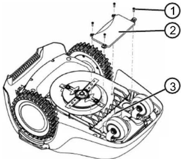
- Unscrew the screws (1).
- Remove the battery compartment cover (2).
- Disconnect the battery (3) and remove it.
- Replace the cover and tighten the screws.
13 TROUBLESHOOTING
13.1 Correcting device and processing errors

CAUTION!
Injury hazard
Moving parts and parts with sharp edges can cause injury.
Always wear protective gloves during maintenance, care, and cleaning!
| Henschprabnoctb PrinuHa | Cnocobly uystaHeHn |
| UcTpoiCTBO He 3anyskaet- cya. | AkkymyIaTOp pa3pJxKeH. 3aRpy3nte yCtPoIcTBo B 3apJdHyIO CTaHcIIO. |
| UcTpoiCTBO nepeMeIaTe- cya C TpydOM n 3akIINHbA- et. Koleca npodoljauOT bpaasatbcry. | DAtChkUyIapa He cpa6aBtI- baIOT. |
| Tpaba cIiShKoM BvICokay. | |
| UcTpoiCTBO 3akIINHbAeT Ha HepOBHoCTyx Ra3OHa. | |
| UcTpoiCTBO BvIIOJIHneT cKaIINBaHne B HeprabInb- HOe Bpem. | HeprabInbHOe Bpem y- cTPOIcTBa. |
| ДIITeJIbHOcTb cKaIINBaHnY UcTaHOBJIeHa HEPrabInbHO. | |
| HAcTpoIeN BpemHn YcTPOI- cTBA He COXPAHJOTcY. | |
| ДВИrataJIb OCTaHavbluBa- eTcR BO Bpem KoUeHnY. | ДВИrataJIb NepeRpyJen. OTKIouHTe UcTPOIcTBo, PomeCTIte erO Ha ПLOCKUO NOBEXHOCTb ИПи HA N3Kу-ю TpaBy, I ChOBA 3aPycTHe. |
| AkkymyIaTOp pa3pJxKeH. 3aRpyIte aKKymyIaTOp. | |
| Hox 3aTyIIncI. ПОBERHNTe Hox ИПи рп HeO6XODIMo- cTn 3aMeHnTe. | |
| Pe3yIbTaT cKaIINBaHnI HepabHomepHbIy. | ДIITeJIbHOcTb cKaIINBaHnIcIIKOM HN3Kaj. |
| Bpem cKaIINBaHnIcIIKOM 6OJIbSoe. | |
| BbICota cpe3a haxOdiNTcRa HN3KOM yPobHe. | |
| Hox 3aTyIIncI. ПОBERHNTe Hox ИПи рп HeO6XODIMo- cTn 3aMeHnTe. |
Chairman of the Board of Management
S. Reiser
Director Regulatory Affairs & Certification
TRANSLATION OF THE ORIGINAL OPERATING MANUAL
Contents
1 Operating manual 411 1.1 Symbols and signal words 411 2 Device description 411 2.1 Scope of delivery 411 2.2 Gas cartridge operation 412 2.3 Device symbols 413 2.4 Control panel 413 2.5 Display 414 2.6 Menu structure 415 2.7 Charging station 416 2.8 Built-in battery 416 2.9 Function description 417
3 Safety 417
3.1 Intended use 417 3.2 Possible incorrect use 417 3.3 Prohibited and protective elements 418
3.3.1 Entering the PIN code and PUK code 418 3.3.2 419
3.4 Safety regulations 419
3.4.1 Operators 419 3.4.2 Personal protective equipment 420 3.4.3 Safety of people and animals 420 3.4.4 Device safety 421 3.4.5 Electrical safety 421
4 Assembly 421
4.1 Device identification 421 4.2 Planning the mowing area (01) 421 4.3 Preparing the mowing area 422 4.4 Installing the charging station (03/a) 422
4.5 Installing the boundary cable 422
4.5.1 Connecting the boundary cable to the charging station (03/b) 422 4.5.2 Laying the boundary cable (01) 422 4.5.3 Insulating the joints 423 4.5.4 Crossing points (01/h) 424 4.5.5 Extending the cable 424 4.5.6 Laying the spare cable (07) 424 4.5.7 Typical errors when laying the cable (02) 424
4.6 Connecting the charging station to the power supply (04) 424 4.7 Checking the connection to the charging station (04) 425
5 Commissioning 425
5.1 Charging the battery (08) 425 5.2 Setting the basic parameters 425 5.3 Adjusting the cutting height 426 5.4 Performing automatic calibration 426
6 Operation 427
6.1 Starting the device manually 427 6.2 Canceling the scheduled mowing time 427 6.3 Mowing an additional area (01/NF) 427
7 Settings 427
7.1 Setting options - General 427 7.2 Enabling/disabling the signal tone at the charging station 428 7.3 Enabling/disabling the ECO mode 428 7.4 Setting the PIN code 428
7.5 Setting the mowing programs 429
7.5.1 Setting the mowing programs - General 429 7.5.2 Setting the entry points 429 7.5.3 Setting the mowing times 429
7.6 Mowing the edges during manual start 430 7.7 Setting the mowing of additional areas 430 7.8 Setting the display contrast 430 7.9 Protecting the settings 430 7.10 Recalibration 430 7.11 Restoring the factory settings 431
8 Information display 431 9 Maintenance and care 431
9.1 Cleaning 431 9.2 Regular testing 432 9.3 Replacing the blade 432
10 Transportation 433 11 Storage. 433
11.1 Storage of used gas masks 433 11.2 Storage of a charged station 433 11.3 Storage of service cable in winter period 434
12 Disposal 434 13 Troubleshooting 436
13.1 Troubleshooting of device malfunctions and processing 436 13.2 List of malfunctions and troubleshooting 437
14 Warranty 441 15 Declaration of Conformity with EU standards 441
1 INFORMATION ABOUT THE OPERATING MANUAL
The German version is the original operating manual. All other language versions are translations of the original operating manual. You must read this operating manual before putting the device into operation. This is a prerequisite for safe and trouble-free operation. Keep this operating manual close at hand so that anyone who needs information about the device can find it. Pass the device on to other persons only together with this operating manual. Read and follow the safety instructions and warnings contained in this entire operating manual.
1.1 Symbols and signal words

DANGER!
Indicates a hazardous situation which, if not avoided, will result in death or serious injury.

WARNING!
Indicates a potentially hazardous situation which, if not avoided, could result in death or serious injury.

CAUTION!
Indicates a potentially hazardous situation which, if not avoided, may result in minor or moderate injury.
NOTE!
Failure to comply with this situation may lead to a sudden breakdown.

MARKING
Special inserts for proper understanding and placement of the probe.
2 DESCRIPTION OF THE DEVICE
This document fully describes the automatic battery-powered grass trimmer, which is independently moved by a gas engine. The cutting height is adjustable.
2.1 Scope of Delivery
The scope of delivery includes the listed items. Check the presence of all items:
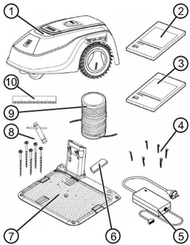
No.
Item
Component
1 Battery-powered grass trimmer 2 Short manual 3 Operating manual
Do not step on the device!
2.4 Control Panel
134 2
HOME
MENU
ON
START
STOP
87656
Component menu
1
(Home button): by pressing the button, the device returns to the initial state. The device automatically turns off after the set time has elapsed.
2 Door sensor: detects the door position (see section 7.4 "Installing the door sensor", page 428).
3 Display: shows the current state of the device, the name of the selected menu, menu items, and selected functions (see section 2.5 "Display", page 414).
4
(Arrow buttons): select menu items, increase and decrease numeric values, select settings.
5
START (Start/Stop button): start and stop scanning manually or resume scanning immediately after pressing the button.
6
(Function buttons): The function that is selected using the button on the display.
7
ON (On/Off button): turning the device on and off.
8
(Menu button): calling up the main menu
2.5 Display
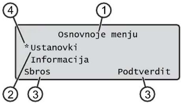
3.2 Module misuse
The device is not intended for use in parks, squares, sports grounds, as well as in agricultural and forestry.
3.3 Safety and protective elements

WARNING! Risk of injury
Malfunction or absence of safety and protective elements can lead to serious injuries.
Faulty safety and protective elements must be repaired immediately. Under no circumstances should you operate the device without safety and protective elements.
3.3.1 Entering the PIN code and PUK code
The PIN code can be changed, see section 5.2 "Setting basic parameters", page 425.
If the PIN code is entered incorrectly three times, the PUK code (personal unlocking key) must be entered. If it is also entered incorrectly, you must wait 24 hours before entering again.
Keep the PIN code and PUK code secret. Use them to protect against unauthorized access.
Keep the PIN code and PUK code in a place inaccessible to third parties.
3.3.2 Sensors
The device is equipped with several safety system sensors. It does not restart automatically after being turned off with a safety system sensor. A fault indication is displayed on the display and must be confirmed. The cause of the sensor activation must be eliminated.
Tilt sensor
If the device is tilted from the housing during operation, the protective mechanism is activated and the device turns off.
Do not press the device!
Watch out for children!
During operation, make sure that children and other persons do not stay near the device, do not touch the device, and do not play with it.
It is forbidden to operate the device and touch it with your feet! Keep a safe distance from the working tool.
3.4.4 Device safety
Before starting work, make sure that there are no objects in the working area of the device (for example, blocks, pieces of glass, metal, fabric, stones, your own furniture, your own tools, or other items). They may be damaged by the device or damage the device. Use the device only under the following conditions:
If it is not clogged; if it is not damaged and not worn; if all control elements work properly. If the charging station and the charging block are not damaged, and the electrical cables are not damaged and are in good condition.
Always replace all faulty parts with original spare parts from the manufacturer. If the device is damaged, repair it immediately. The owner of the device bears personal responsibility for accidents involving other persons or their property.
3.4.5 Electrical safety
Do not use the device without a properly grounded installation. - Avoid splashing water on the device. Do not open the device.
ASSEMBLY
4.1 Unpacking the device
1. Carefully remove the packaging. 2. Carefully remove all components from the packaging and check for any damage during transport.
Note: In case of damage during transport, please contact your dealer or the Karcher service center immediately, in accordance with the warranty terms.
If you want to return the device, keep the original packaging and the accompanying documents. They are also necessary for a return and for shipping.
4.2 Planning the mowing area (01)
Placement of the charging station (01/1)
Shortest route to the largest mowing area. Level surface. Protection from direct sunlight and strong weather conditions. Possibility of connecting to the power supply and free access for operation of the robotic lawnmower.
Laying the boundary cable (01)
The boundary cable must be laid without interruption and checked continuously.
Passage through mowing areas (01/h)
The passage is a narrow strip of lawn that can serve to connect two mowing surfaces.
Main and secondary areas (n) (01)
Main area (01/HF): The sensor, on which the charging station is installed, can automatically fold using the device on all areas. Additional area (01/NF): This is a sensor that the device cannot reach from the main area. The device must be manually moved to the additional area. Additional areas can be processed in continuous operation mode.
Both main and additional areas are enclosed by the same boundary cable.
Positioning of the input terminals (01/X0-01/X3)
The device is connected to the boundary cable with a fixed time for folding the fixed input terminals and begins with tampering.
The input terminals allow you to specify which areas of the folding area have been folded.
You can combine both variants.
WARNING!
Danger of damaging the boundary cable
If the boundary cable is damaged or torn, the device will no longer be able to receive control signals. In this case, the boundary cable must be repaired or replaced. The boundary cable is available from Karcher.
Always lay the boundary cable directly on the ground. If necessary, secure it with additional fasteners for fixing the boundary cable. Protect the boundary cable from damage during installation and operation. Do not dig or perform vertical work with the boundary cable.
- Lay the boundary cable through the guide slots using the fasteners for fixing the boundary cable or with ground spikes (maximum 10 cm).
- Lay the boundary cable around obstacles: see section 4.5.3 "Bridging obstacles", page 423.
- Create passages between separate mowing areas: see section 4.5.4 "Creating passages (01/h)", page 424.
- To exclude large slopes or transitions: see section 4.5.5 "Avoiding transitions", page 424.
- Lay the charging cable: see section 4.5.6 "Laying the charging cable (07)", page 424. 6. After completing the installation, connect the boundary cable to the charging station (03/B) according to the connection diagram: see section 4.5.1 "Connecting the boundary cable to the charging station (03/b)", page 422.
4.5.3 Obstacles
Depending on the type of obstacle, the routing cable must be laid at different distances from obstacles. To determine the correct distance, use the ruler that is attached to the packaging.

RULER
Remove any obstacles that could be detected by the motion sensors of the device. Remove a large number of obstacles or unnecessary objects. Objects smaller than 6 cm must be insulated, otherwise the device may be damaged.
Distance to walls, fences, flower beds: min. 20 cm (01)
The device changes its direction when it is 20 cm away from the boundary cable. Therefore, lay the boundary cable at a distance of no less than 20 cm from walls, fences, flower beds, etc.
Distance to terrace edges and paved paths (05)
If the terrace or the edge is higher than the lawn, then a distance of no less than 20 cm must be maintained. If the terrace or the edge is at the same height as the lawn, then the cable can be laid exactly at the edge.
Distance between the boundary cable and obstacles (01)
If the boundary cable is laid without insulation directly next to an obstacle or on it, i.e., at a distance of 0 cm, the device will cross over the boundary cable. Do not cross the boundary cable (02/c), but lay it parallel (01/e).
Laying the boundary cable in corners (06)
For inner corners (06/a): lay the boundary cable diagonally to avoid the device getting stuck in the corner. For outer corners with obstacles (06/b): lay the boundary cable with a pointed end to avoid the device colliding with the corner. For outer corners without obstacles: lay the boundary cable at a 90-degree angle.
4.5.4 Passage width (01/h)
Maintain the specified minimum distances in passages:
Total width: min. 60 cm Distance of the boundary cable to the edge: 20 cm Distance between boundary cables: min. 30 cm
4.5.5 Height difference
If the height difference exceeds 45%, a shielded cable must be used (45% = a drop of 45 cm for every 1 m horizontally).
4.5.6 Laying cable slack (07)
To be able to move the charging station or expand the charging area after commissioning the charging area, adjust the cable slack in the shielded cable.
The amount of cable slack can be set at your own discretion.

NOTE
Indicates open loops in case of cable slack.
1. Lay the shielded cable along the belt fastener for mounting the shielded cable (07/1), and then
go to the cross fastener for mounting the shielded cable (07/3).
- Then lay the shielded cable along the belt fastener for mounting the shielded cable, forming a loop. The cable must fit tightly.
- If necessary, adjust the loop inside using the additional fastener for mounting the shielded cable (07/2) on the ground.
4.5.7 Typical errors during cable laying (02)
The shielded cable slack is not installed in a uniform surface loop (02/a). The shielded cable is correctly installed around corners (02/b). The shielded cable is crossed or not laid in the direction of the gas flow (02/c). The shielded cable is installed too far from the correct gas shut-off point (02/d). The transition point from the switch to the gas shut-off shielded cable is not laid directly at the switch (02/e). The entry point is installed too far from the charging station (02/f). The shielded cable is laid along the edge of the gas zone (02/g). During the laying of the shielded cable, the minimum distance for passage of 30 cm is exceeded (02/h). The shielded cable is located too close, i.e., at a distance of less than 20 cm, to obstacles that can be crossed (02/i).
4.6 Connecting the charging station to the power supply unit (04)
- Place the power supply unit (04/4) in a dry place away from direct sunlight, in sufficient proximity to the charging station (04/1). 2. Connect the power cable of the power supply unit (04/5) and the cable of the charging station (04/6).
- Connect the power supply unit (04/2) to the socket (04/3).

NOTE
We recommend connecting the power supply unit to the mains via a protective switching device, which ensures reliable disconnection at a rated current of ≤ 30 mA.
4.7 Checking the connection to the charging station (04)
- Check whether the indicator on the front of the charging station (09/1) lights up. If not:
Check the plug. Verify the correct positioning and the absence of damage to all plug connections of the power supply unit and the connecting cables.
Indicator statuses
Light indicators
Green
Operating conditions
Lights up when the connecting cable is correctly installed and the circuit is not damaged. Blinks if the connecting cable circuit is not in order.
Red
Lights up if the power supply unit is damaged.
5 INITIAL OPERATION
This section describes the conditions and parameters necessary to start the device and perform initial operation. For other settings, see section 7 "Settings", page 427.
5.1 Charging the battery (08)
The battery is built into the device and is included in the delivery set. During normal operation, the battery is automatically charged regularly.

NOTE
The battery must be fully charged before first use. The battery can be charged at any charge level. Interrupting the charging process does not affect the battery condition.
The battery can only be charged when the device is switched off.
- Place the device (08/1) on the charging station (08/3) so that the contact surface of the device contacts the charging contact of the charging station.
- Switch on the device using the ON/OFF button.
- The display shows: Battery is charging. If not, see section 13 "Troubleshooting", page 436.
5.2 Setting basic parameters
- Open the cover.
- Switch on the device using the ON button. The firmware version, code number, and type are displayed.
- In the language selection menu, select the language using the buttons and confirm with button 4. In the menu Registration > Enter PIN, enter the PIN code as prompted: 0000. Select the country using the buttons and confirm with the button. After entering the PIN code, access is unlocked.
5. In the menu Change PIN:
Enter the new PIN. Select the digits one by one using

or confirm using

Enter the new PIN again. If the entered digits match, a message will appear that the PIN has been successfully changed.
- In the menu, enter the current date (format: DD.MM.YYYY). Select the digits one by one using

and confirm using.
- In the menu, set the time in 24-hour format. Enter the current time (format: HH:MM). Select the digits one by one using
one by one using

confirm
using
Basic settings are set. The status is displayed as not calibrated. Press the START button.
5.3 Setting the cutting height
The cutting height is continuously adjustable from 25 to 55 mm.

NOTE
For calibration (see section 5.4 "Performing machine calibration", page 426) and for setting the feed opening (see section 7.5.2 "Setting the feed opening", page 429), a cutting height of 55 mm is recommended.
1. Open the cover (10/1).
- The cutting height (in the main window in millimeters, the exact cutting height is displayed (10/3)):
Increasing the cutting height (i.e., the mowing height): turn the rotary knob (10/2) clockwise (10/+). Decreasing the cutting height (i.e., the mowing height): turn the rotary knob (10/2) counterclockwise (10/-).
3. Close the cover.
5.4 Performing automatic calibration
Setting the initial position of the device (09)
- Set the device for the mowing area to the initial position:
Min. 1 m before the charging station, align the front part of the boundary cable.
Starting calibration
- Check that there are no obstacles in the expected range of movement of the device. The device must be able to move freely in front of the wheels along the boundary cable. If necessary, remove obstacles.
- Start the device using START. The display shows:
!Attention! Drive start Calibration , Phase
During calibration
To determine the signal level in the boundary cable, the device first runs twice along the boundary cable, then to the charging station and stops there.
The calibration is complete. The accumulator is being charged.

NOTE
At the entrance to the charging station, the device must stop. If the device does not come into contact at the entrance to the charging station, it will continue moving along the designated cable. If the device passes the charging station, this means that the calibration process was not completed. In this case, the charging station must be brought to a proper condition and the calibration process repeated.
After calibration
The charging zone is selected by the duration of charging.
For all other settings, see section "Settings", page 427.

NOTE
To ensure the cleanliness of the sliding, it is recommended that the device be wiped with a dry cloth. This is done during the removal of the device for the purpose of checking the entrance (see section 5.2 "Setting the entry points", page 429).
6 OPERATION
6.1 Starting the device manually
- Turn on the device using ON/OFF. For manual sliding of edges: see section 6 "Sliding edges during manual start", page 430.
- Start the device using STOP
6.2 Stopping operation and charging
Press the button on the device. The device automatically returns to the charging station. It performs the sliding of the current edge and restarts the next day at the set time. Press the button on the device. The operation in the sliding mode is interrupted. Press the ON button on the device. The device turns off.

NOTE
In unforeseen situations, the device can be turned off using the STOP button (08/2).
6.3 Compacting the additional area (01/NF)
1. Lift the device and install it inside on the additional area. 2. Turn on the device using ON/OFF. 3. Turn on the main menu using . 4. a * settings 5. a * additional area compaction 6. Select the compaction mode using or 7. Start the device inside using STOP
Depending on the settings: The device performs compaction for a set time, and then turns off or continues compaction until the battery is discharged.
The compaction of the additional area again returns the device to the charged state.
7 SETTINGS
7.1 Turning on settings - general
- Turn on the main menu using . Note: The asterisk * before a menu item indicates that it is not yet selected.
- a * settings
- Select the desired menu item using 50 and confirm using
- Set the settings. Note: The menu items are described in the following sections. 5. Return to the main menu using

NOTE
Other menu items: see section 5.2 "Setting the main parameters", page 425.
7.2 Turning on/off the signal of key presses
- aoe * key presses
- Pressing/releasing the button:
or activate: 0
Pressing the button.
or deactivate: 0
Pressing the button
7.3 Pressing/releasing Eco mode
In Eco mode, the device switches to energy-saving mode. The energy consumption level is lower.

NOTE
This mode is not recommended or not available in case of high and full load, as well as full load of the gas cylinder.
- Mode
2. Pressing/releasing Eco mode:
Activate: 0
Pressing Eco mode.
7.4 Installing the rain sensor

RAIN SENSOR
Mowing wet grass reduces the amount of clogging.
Activating the rain sensor before the set delay time can prevent clogging of the device with wet grass.
When the rain sensor is activated, the device returns to the charging station, when it rains. It stays there until the rain sensor dries out. Then it resumes operation after the set delay time, before continuing the mowing operation. The rain sensor sensitivity is adjustable.
- a * rain sensor
2. Activating the rain sensor:
a) Activate:
Activate the rain sensor.
b) Deactivate:
Deactivate the rain sensor.
3. Setting the rain sensor delay time:
a) Rain delay
xx hours xx minutes Set the delay value using , confirm with
4. Setting the duty cycle of the sensor:
or sensor value
Select the desired duty cycle value using , confirm with
7.5 Programming the scanner
7.5.1 Programming the scanner - general
- Turn on the main menu using .
- a * Program 3. Select the menu item using and confirm with
- Set the programming. Note: The menu items are described in the following sections.
7.5.2 Setting the input points
Enabling the input points
- Set the device to the charging station.
- Turn on the device using ON OFF
- Turn on the main menu using .
- a * Rgrammy
- a * Start point
- a * Route definition
- a * Start of familiarization ride through start points
a6o start .Icpii nepeMiuaeTbcB3doBx 06MexyBaIbHoro Ka-6enl. a6o des', npicpii DocraHyB 6axaHOI TOck BxOy. Tocka BXOy 36epiraetbcra.
- a Enter start point 1
D,ЯкsoTOyKa BXOy He 3aHaHa NiД Yac HABaJIbHOI NOI3dKn.ЯкsoTOuyBXOy He 3aHaHO,To TOUYKIN BXOy6yde BCTaHOBNeHO ABTomaTnHOr.
- aPunstartax:XXm, 0
KoIIN 6yInO DOcRHyTO OCTaHHboi TOUKN BXO- dy.
BcTaHOBJIeHHr ToOK BxOy BypyHy (01)
Nepwa Toka BxOy (01/X0) 3aHa i 3hAxoNTbCraB 1 M npabopyu BiD 3apAHOI cTAnCi. 3a ciEToTOKOMoXHa 3anporpaMyBaTu Do 3doaTKOBHX TOOK BxOy (BiD X1 do X3).PiJ vac BcTaHOBJIeHnRA TOOK BxOy 3BepHITb yBary Ha Take:
He BcTaHOBIIOTe TOCK BxOy 3aHaITo Da- neko Bi, 3apAHOi cTAnci i a6o dyke 6n3bko Onda oOnoi (02/f). BukopncToByTe TInbKn CTInbKn ToOk BxOy,CKInbKn Heo6xIDHO.
- a * Start point 0 2.a * Point X1 at [020m] Select one digit with or confirm with . 3.a * Point X2 at [075m] Select one digit with or confirm with .
- If necessary, set additional entry points. 5. Return to the main menu using
7.5.3 Setting the washing time

NOTE
Between the programmed washing time and the start of washing, there must be at least 30 minutes. Otherwise, the device will not start until the next programmed washing time.
The Programma nedeli menu item is used to set the washing time for the device. If necessary, set the time according to the desired size. If you select unwashed days, the washing time will be increased.
- a* Programma nedeli
or Vse dni [X]: the device performs washing once at the set time. If Vse dni [ ] is displayed, the device will perform washing only on the set days. or Ponedel'nik [X]...Voskresenje [X]: the device performs washing on the set days. For example, if Ponedel'nik [ ] is displayed, the device cannot perform washing on that day.
or zmenit': press [X] or press [] on the corresponding day, set the time, washing time, and entry points.
2. Setting the timer for all days or one day:
For example, *[M]07:00-10:00[?]: the washing cycle [M] from 07:00 to 10:00 automatically changes the entry points to 0-3[?]. For example, [R] 16:00-18:00 [1]: the device starts at 16:00 in washing mode [R] and is transferred to the entire volume of the specified channel. After this, the washing of the second one starts from entry point 1 [1]. At 18:00 or when the accumulator is discharged, the device returns to the pre-set station. or zmenit': remove the selected timer. or pered: return the timer changes to the previous ones.
- a SoHanite: save the timer changes in the menu item.
- a@ * zvodskie ustanovki 0
Message: Settings successfully restored
8 INFORMATION
Menu information and display of the norm for the device. This menu can be used to set the language.
- Use the main menu with the help of .
- a* information
- Select a menu item with the help of
and confirm with the help of O
Note: The menu items are described in the following paragraphs.
4. Return to the main menu using
MOTOO
Knife service
Displays the operating hours required for knife maintenance. The counter can be reset manually. Entrust knife maintenance to specialists, technicians, or the Karcher service partner.
Resetting the knife maintenance counter:
- Confirm
Hardware
Displays information about the device, such as the model, year of manufacture, operating hours, serial number, number of blades in the set, total operating time, number of charging cycles, total charging time, and the length of the supply cable.
Software
Software version.
Program Info
Displays the current settings, which cover the entire scrolling time for the day.
Faults
Displays the latest notifications about errors with date, time, and error code.
9 TECHNICAL MAINTENANCE AND CARE
WARNING! Danger of injury from moving parts and parts with sharp edges. They can cause injury.
Wear protective gloves during technical and service maintenance and cleaning!
9.1 Cleaning
CAUTION! Danger due to damage to the robotic mower and charging station caused by a pressure washer. It can cause damage to electrical components.
Do not spray the robotic mower and charging station with water.
Cleaning the robotic mower

WARNING! Danger of injury from the blade.
The blade is sharp and can cause injury.
Use protective gloves! Make sure that the parts of the body do not come into contact with the blade.
Perform once a week:

- Clean the device with
- Wipe the surface of the housing with a soft, damp cloth or a soft sponge.
- Clean the bottom, the brush, and the suction nozzle.
- Check the nozzle for damage. Replace if necessary: see section 9.3 "Replacing the nozzle", page 432.
Cleaning the charging station
- Regularly remove grass and leaves or other debris from the charging station.
- Clean the surface of the charging station with a damp cloth or a soft sponge.
9.2 Regular testing
General testing
- Check the entire device once a week for damage:
Charging station, connecting cable, power supply
- Replace defective parts with original spare parts from Kärcher or have them replaced by the Kärcher service center.
Checking the free movement of the rollers
Perform once a week:
- Clean the blades and the area around them of grass and dirt. Use a brush and a cloth. 2. Make sure that the blades move freely.
Note: If the blades do not move freely or cannot be moved, contact the Karcher service center.
Checking the contact surfaces for wear on the mower
- Clean the blades with a cloth and lightly apply a consistent lubricant.
Checking the charging contacts on the charging station
- Pull out the plug.
- Press and release the charging contacts in the direction of the charging station. The charging contacts must return to their initial position.
Note: If the charging contacts do not return, contact the Karcher service center.
9.3 Replacing the blade

WARNING! Risk of injury from the blade
The blade is very sharp and can cause injury.
Wear protective gloves! Make sure that the blade does not come into contact with the cable.
CAUTION!
Remove the battery before disposing of the device
Before disposal, the built-in battery must be removed and disposed of separately in an environmentally friendly manner.
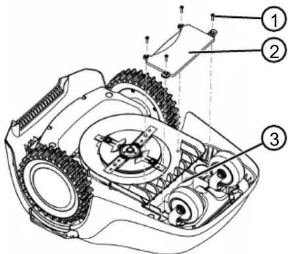
- Tighten the screw (1).
- Remove the battery cover (2).
- Take out the battery (3) and dispose of it.
- Reinstall the cover and tighten the screw.
13 TROUBLESHOOTING
13.1 Troubleshooting of device malfunctions and processing

CAUTION! Risk of injury
Moving parts and parts with sharp edges can cause injury.
Wear protective gloves during technical and service maintenance and cleaning!
| Hecnpabnictb PrunuHa YcunHeHn | |
| Пристрии не запись. Актуларов розджени. 3ардіт b писстрии в запись. | |
| Пристрии посяпаетбя 3усшилам i зашилоч. Ко- leca поювкуоть обер- taiися. | |
| Трава занадто виска. 36ьшte висOTу 3рizанн, a notim постуноу 3мeншуITE IIdo Heo6-xiДhoI BricOTn.СкшуITE ra30н ra30нokocapкю npotrayom koperKorOчacy. | |
| Пристрии запись на не- рibnoctях ra30Hy.Усныт не рсivностi. | |
| Пристрии висиуЕ сokoшу- Bavни в неравильни чac. | |
| Несравильни чac посту.Всаліstь сokoшвань всяновке на неравильни. | |
| Налашу Bavни час посту.Зрочу висOTуцHTу komпапii Kärcher. | |
| Двиун зушиностяпд chac scokoшуВанни. | |
| Двиун посяпаетжени. Вимкіт b писстriи, bztahoviteb myoro na Ппосу поразхию abo Na Hn3bky Trpaby, i 3HOBy 3anyctITb. | |
| Актуларов розджени. 3ардіт b akumулайор. | |
| Hix 3atynibcra. Поверніт bix abo 3a noTpe6n 3amihitb. | |
| Рezшытат scokoшуВанни Неріномірни. | |
| Траваліstь scokoшвань 3a- habto habka.3anporpamyte biusу trpbaniciCTbСokoшвань. | |
| Час scokoшвань 3ahandTo Beлики.3menшіт b oblaactb scokoшвань. | |
| Висota 3рizanня 3naXODntb- ся на habkOMу pIBhi.36ьшte висOTу 3рizanн, a notim no-ctynobO 3mehyute IIdo Heo6xidhoI BincOTn. | |
| Hix 3atynibcra. Поверніт bix abo 3a noTpe6n 3amihitb. |
Malfunction Cause Remedy
| Тривалиstь роботи вд a- куменялара счтево 3ни- зилася. | Висota зрizaаня знховпь- ся на НИЗКOMу рIBni. | 36iльшte висOTу зрizaаня, a notim постунов 3мeншуйte ii do Heoobxidnoi BисOTи. |
| Трава занадто виска abo надTo ВОлогa. | ■ BiДкл actи скошуваня, поки не пдcoхне травa. ■ HanaштуйTe висOTу зрizaаня на 6iNbш вискOn рIBeHb. | |
| Вібрація abо рунісъ п ri- stpoю занадто виски. | ДиSCБаланс HOжа abo мexа- Hi3My puXY HOжа | ■ Oчіstіть кocapку. ■ 3berhітьсяdoes copbivchOrо ceHTpy kompanii Kârcher. |
| Акymулайтор He заряджа- оъсяа abо мa'e НИЗыку Ha- npугy | ■ 3apядNi KOntaKTи Na 3a- рядNi STaHцIl 3a6pud- HeNi. ■ KontaKTHi NOBepxHi Na pricSTpoI 3a6pudHeNi. | Oчіstіть зарядNi KOntaKTи i KOntaKTHi nobepxHi. |
| Ha zapordny ctsanziu He no- daCTbCS JKNBJIeHNry. | Підклічіть зарядHu ctsanziu do 6lOKyЖИВЛeHNry. | |
| ■ Пpriztrpiй He cumichni 3 3apяднIMn KOntaKTamN. ■ KontaKTHi NOBepxHi Na pricSTpoI 3rOpilN. | ■ BcStavte priztrpiй b 3apядHu ctsanziu i nepebipte Na rambHicTb 3apядHuX KOntaKTiB. ■ 3berhіtseydo copbivchOrо ceHTpy kompanii Kârcher. | |
| Терmin сFlyжби akumylЯto- pa 3abepshinBcRy. | 3berhіtseydo copbivchOrо ceHTpy kom- panii Kârcher. | |
| Зарядna eilektroponika He- cnравнa. | 3berhіtseydo copbivchOrо ceHTpy kom- panii Kârcher. |

NOTE
If malfunctions occur that are not listed in this table, or malfunctions that the user cannot resolve, contact the service department.
13.2 Faults and troubleshooting
Relevant Directives EC
2006/42/EC (+2009/127/EC)
2014/30/EC
2009/125/EC
2011/65/EC
2014/53/EC
Person responsible for compiling the documentation
S. Reiser
Applied harmonized standards
EN 60335-1
EN 50636-2-107:2015
EN 61558-1
EN 61558-2-16
EN 62233:2008
EN 50563
EN 50581
Subject to the provisions of other regulations.
Winnenden, September 1, 2018
H. Jenner
Chairman of the
Board of
Management
S. Reiser
Director Regulatory Affairs & Certification



- ABOUT THESE OPERATING INSTRUCTIONS
- LEGENDS AND SIGNAL WORDS
- DANGER
- WARNING
- CAUTION
- IMPORTANT
- NOTE
- PRODUCT DESCRIPTION
- SCOPE OF SUPPLY
- NO. COMPONENT
- SYMBOLS ON THE APPLIANCE
- MENU STRUCTURE
- CHARGING STATION
- INTEGRATED BATTERY
- FUNCTIONAL DESCRIPTION
- MOVING ON THE GRASS SURFACE
- MOWING AND CHARGING
- SAFETY
- INTENDED USE
- POSSIBLE MISUSE
- SAFETY AND PROTECTIVE DEVICES
- RISK OF INJURY
- PIN AND PUK INPUT
- SENSORS
- LIFTING SENSOR
- BUMP SENSORS FOR OBSTACLE DETECTION
- TILT SENSOR IN DIRECTION OF TRAVEL/SIDEWAYS
- RAIN SENSOR
- SAFETY INSTRUCTIONS
- OPERATOR
- PERSONAL PROTECTIVE EQUIPMENT
- SAFETY OF PERSONS AND ANIMALS
- AUTOMATIC LAWN MOWER IN OPERATION
- APPLIANCE SAFETY
- ELECTRICAL SAFETY
- ASSEMBLY
- UNPACKING THE MACHINE
- PLANNING THE MOWING AREAS (01)
- LOCATION OF THE CHARGING STATION (01/1)
- ROUTING THE BOUNDARY CABLE (01)
- CORRIDORS BETWEEN MOWING AREAS (01/H)
- MAIN AREA AND SECONDARY AREA(S) (01)
- POSITION OF THE ENTRY POINTS (01/X0 - 01/X3)
- PREPARING THE MOWING AREAS
- SETTING UP THE CHARGING STATION (03/A)
- INSTALLING THE BOUNDARY CABLE
- CONNECTING THE BOUNDARY CABLE TO THE CHARGING STATION (03/B)
- IMPORTANT! DANGER OF DAMAGING THE BOUNDARY CABLE
- EXCLUDING OBSTACLES
- DISTANCE FROM WALLS, FENCES, BEDS: MIN. 20 CM (01)
- DISTANCE FROM TERRACE EDGES AND PAVED PATHS (05)
- DISTANCE OF OBSTACLES FROM THE BOUNDARY CABLE (01)
- ROUTING THE BOUNDARY CABLE AROUND CORNERS (06)
- ENCLOSING CORRIDORS (01/H)
- EXCLUDING DOWNWARD SLOPES
- CREATING LOOPS OF CABLE (07)
- TYPICAL FAULTS IN CABLE ROUTING (02)
- CONNECTING THE CHARGING STATION TO THE POWER SUPPLY (04)
- CHECKING THE CONNECTIONS ON THE CHARGING STATION (04)
- STATUS INDICATIONS OF THE LEDS
- LEDS OPERATING STATES
- START-UP
- CHARGING THE RECHARGEABLE BATTERY (08)
- MAKING THE BASIC SETTINGS
- SETTING THE CUTTING HEIGHT
- CARRYING OUT AN AUTOMATIC CALIBRATION MOVEMENT
- PLACE THE APPLIANCE AT THE STARTING POSITION (09)
- STARTING THE CALIBRATION MOVEMENT
- DURING THE CALIBRATION MOVEMENT
- AFTER THE CALIBRATION MOVEMENT
- OPERATION
- STARTING THE APPLIANCE MANUALLY
- CANCELLING MOWING
- MOWING THE SECONDARY AREA (01/NF)
- SETTINGS
- CALLING UP THE SETTING - GENERAL
- ACTIVATING/DEACTIVATING THE BUTTON TONES
- ACTIVATING/DEACTIVATING ECO MODE
- SETTING THE RAIN SENSOR
- SETTING THE MOWING PROGRAM
- SETTING THE MOWING PROGRAM - GENERAL
- SETTING ENTRY POINTS
- LEARNING ENTRY POINTS
- MANUALLY SPECIFYING ENTRY POINTS (01)
- SETTING THE MOWING TIMES
- EDGE MOWING WITH A MANUAL START
- SETTING THE SECONDARY AREA MOWING
- SETTING THE DISPLAY CONTRAST
- SETTING LOCK
- RECALIBRATING
- RESTORING FACTORY SETTINGS
- DISPLAYING INFORMATION
- BLADES SERVICE
- HARDWARE
- SOFTWARE
- PROGRAM INFO
- FAILURES
- MAINTENANCE AND CARE
- CAUTION! RISK OF INJURY
- CLEANING
- DANGER FROM WATER
- CLEANING THE AUTOMATIC LAWNMOWER
- DANGER OF INJURY DUE TO THE CUTTING BLADE
- CLEANING THE CHARGING STATION
- REGULAR CHECKS
- GENERAL CHECKS
- CHECK THE ROLLERS CAN MOVE FREELY
- CHECK THE CONTACT SURFACES ON THE AUTOMATIC LAWNMOWER
- CHECK THE CHARGING CONTACTS OF THE CHARGING STATION
- REPLACING THE CUTTING BLADES
- CAUTION! DANGER OF INJURY DUE TO THE CUTTING BLADE
- DAMAGE TO THE APPLIANCE DUE TO INCORRECT REPAIR
- TRANSPORT
- STORAGE
- STORING THE AUTOMATIC LAWNMOWER
- STORING THE CHARGING STATION
- IF THE CHARGING STATION REMAINS OUTDOORS
- WHEN THE CHARGING STATION IS TO BE PUT INTO STORAGE
- IF ONLY THE CHARGING POLE IS STORED
- WINTER STORAGE OF THE BOUNDARY CABLE
- DISPOSAL
- INFORMATION ON THE GERMAN ELECTRICAL AND ELECTRONIC EQUIPMENT ACT (ELECTROG)
- INFORMATION ON THE GERMAN BATTERY ACT (BATTG)
- INFORMATION ON PACKAGING
- REMOVE THE RECHARGEABLE BATTERY BEFORE DISPOSING OF THE APPLIANCE
- HELP IN CASE OF MALFUNCTION
- CORRECTING APPLIANCE AND HANDLING FAULTS
- FAULT CODES AND TROUBLESHOOTING
- GUARANTEE
- EU DECLARATION OF CONFORMITY
- PRODUCT
- MANUFACTURER
- AUTHORISED REPRESENTATIVE
- TYPE
- RELEVANT EU DIRECTIVES
- APPLIED HARMONISED STANDARDS
- TRANSLATION OF THE ORIGINAL USER MANUAL
- TABLE OF CONTENTS
- DISPLAY INFORMATION
- TRANSLATION OF THE ORIGINAL INSTRUCTIONS
- TRANSLATION OF THE ORIGINAL INSTRUCTIONS FOR USE
- SUMMARY
- TRANSLATION OF THE ORIGINAL INSTRUCTION MANUAL
- INDEX
- TRANSLATION OF ORIGINAL INSTRUCTIONS FOR USE
- CONTENTS
- PERSON AUTHORIZED FOR DOCUMENTATION
- SETTING MOWING OF ADJACENT AREAS
- PROTECTION OF SETTINGS
- HARMONIZED STANDARDS USED
- TRANSLATION OF ORIGINAL INSTRUCTIONS
- DURING CALIBRATION DRIVE
- PERSON RESPONSIBLE FOR COMPILING THE TECHNICAL DOCUMENTATION
- TRANSLATION OF THE ORIGINAL OPERATING INSTRUCTIONS
- APPLICABLE EU DIRECTIVES
- APPLICABLE EC DIRECTIVES
- AUTHORIZED FOR DOCUMENTATION
- APPLIED HARMONIZED STANDARDS
- TRANSLATION OF THE ORIGINAL OPERATING MANUAL
- INFORMATION ABOUT THE OPERATING MANUAL
- BASIC SYMBOLS AND SIGNAL WORDS
- NOTICE
- SCOPE OF DELIVERY
- DESCRIPTION OF FUNCTIONING
- BEHAVIOR ON THE LAWN
- WORKING TIME, MOWING TIME, CHARGING
- IMPROPER USE
- SAFETY DEVICES
- ENTERING THE PIN CODE AND PUK CODE
- LIFT SENSOR
- PERFORMING AUTOMATIC CALIBRATION
- SETTING THE INITIAL POSITION OF THE DEVICE (09)
- STARTING CALIBRATION
- DURING CALIBRATION
- AFTER CALIBRATION
- CONTROL
- STARTING THE DEVICE MANUALLY
- CANCELING WORK IN SCANNING MODE
- SCANNING ADDITIONAL AREA (01/NF)
- CALLING UP SETTINGS - GENERAL
- ENABLING/DISABLING SIGNALS BY PRESSING BUTTONS
- ENABLING/DISABLING ECO MODE
- INSTALLING THE RAIN SENSOR
- SETTING THE SCANNING PROGRAM - GENERAL
- CALL UP THE MAIN MENU USING
- SETTING ENTRY POINTS MANUALLY (01)
- SETTING THE SCANNING TIME
- EDGE SCANNING WITH MANUAL START
- SETTING SCANNING OF AN ADDITIONAL AREA
- SETTINGS PROTECTION
- RECALIBRATION
- VIEWING INFORMATION
- BLADE SERVICE
- FAULTS
- ATTENTION
- RISK OF INJURY FROM THE BLADE
- REGULAR INSPECTIONS
- GENERAL INSPECTIONS
- CHECKING THE FREE MOVEMENT OF THE ROLLERS
- CHECKING THE CONTACT SURFACES ON THE ROBOT MOWER
- CHECKING THE CHARGING CONTACTS ON THE CHARGING STATION
- RISK OF INJURY FROM CUTS CAUSED BY THE BLADE
- DAMAGE TO THE DEVICE DUE TO INCORRECT REPAIR
- STORING THE ROBOTIC LAWN MOWER
- STORAGE OF THE CHARGING STATION
- FOR STORAGE OF THE CHARGING COLUMN ONLY
- STORAGE OF THE LIMITING CABLE IN WINTER PERIOD
- INFORMATION ACCORDING TO THE LAW ON ELECTRICAL AND ELECTRONIC EQUIPMENT
- INFORMATION ACCORDING TO THE BATTERY LAW
- REMOVE THE BATTERY BEFORE DISPOSING OF THE DEVICE
- TROUBLESHOOTING
- CORRECTING DEVICE AND PROCESSING ERRORS
- INJURY HAZARD
- SYMBOLS AND SIGNAL WORDS
- MARKING
- DESCRIPTION OF THE DEVICE
- COMPONENT
- CONTROL PANEL
- COMPONENT MENU
- DISPLAY
- MODULE MISUSE
- SAFETY AND PROTECTIVE ELEMENTS
- WARNING! RISK OF INJURY
- TILT SENSOR
- DEVICE SAFETY
- UNPACKING THE DEVICE
- PLANNING THE MOWING AREA (01)
- PLACEMENT OF THE CHARGING STATION (01/1)
- LAYING THE BOUNDARY CABLE (01)
- PASSAGE THROUGH MOWING AREAS (01/H)
- MAIN AND SECONDARY AREAS (N) (01)
- POSITIONING OF THE INPUT TERMINALS (01/X0-01/X3)
- DANGER OF DAMAGING THE BOUNDARY CABLE
- OBSTACLES
- RULER
- DISTANCE TO WALLS, FENCES, FLOWER BEDS: MIN. 20 CM (01)
- DISTANCE TO TERRACE EDGES AND PAVED PATHS (05)
- DISTANCE BETWEEN THE BOUNDARY CABLE AND OBSTACLES (01)
- LAYING THE BOUNDARY CABLE IN CORNERS (06)
- PASSAGE WIDTH (01/H)
- HEIGHT DIFFERENCE
- LAYING CABLE SLACK (07)
- TYPICAL ERRORS DURING CABLE LAYING (02)
- CONNECTING THE CHARGING STATION TO THE POWER SUPPLY UNIT (04)
- CHECKING THE CONNECTION TO THE CHARGING STATION (04)
- INDICATOR STATUSES
- INITIAL OPERATION
- CHARGING THE BATTERY (08)
- SETTING BASIC PARAMETERS
- IN THE MENU CHANGE PIN
- OPEN THE COVER (10/1)
- CLOSE THE COVER
- STOPPING OPERATION AND CHARGING
- COMPACTING THE ADDITIONAL AREA (01/NF)
- TURNING ON SETTINGS - GENERAL
- TURNING ON/OFF THE SIGNAL OF KEY PRESSES
- PRESSING/RELEASING ECO MODE
- PROGRAMMING THE SCANNER
- PROGRAMMING THE SCANNER - GENERAL
- SETTING THE INPUT POINTS
- ENABLING THE INPUT POINTS
- BCTAHOBJIEHHR TOOK BXOY BYPYHY (01)
- SETTING THE WASHING TIME
- INFORMATION
- KNIFE SERVICE
- TECHNICAL MAINTENANCE AND CARE
- WARNING! DANGER OF INJURY FROM MOVING PARTS AND PARTS WITH SHARP EDGES. THEY CAN CAUSE INJURY
- CLEANING THE ROBOTIC MOWER
- WARNING! DANGER OF INJURY FROM THE BLADE
- PERFORM ONCE A WEEK
- REGULAR TESTING
- GENERAL TESTING
- CHECKING THE CONTACT SURFACES FOR WEAR ON THE MOWER
- REPLACING THE BLADE
- WARNING! RISK OF INJURY FROM THE BLADE
- TROUBLESHOOTING OF DEVICE MALFUNCTIONS AND PROCESSING
- RELEVANT DIRECTIVES EC
- PERSON RESPONSIBLE FOR COMPILING THE DOCUMENTATION
Brand : Kärcher
Model : RLM 4
Category : Robot mower