
EY7411 - Drill PANASONIC - Free user manual and instructions
Find the device manual for free EY7411 PANASONIC in PDF.
User questions about EY7411 PANASONIC
0 question about this device. Answer the ones you know or ask your own.
Ask a new question about this device
Download the instructions for your Drill in PDF format for free! Find your manual EY7411 - PANASONIC and take your electronic device back in hand. On this page are published all the documents necessary for the use of your device. EY7411 by PANASONIC.
USER MANUAL EY7411 PANASONIC
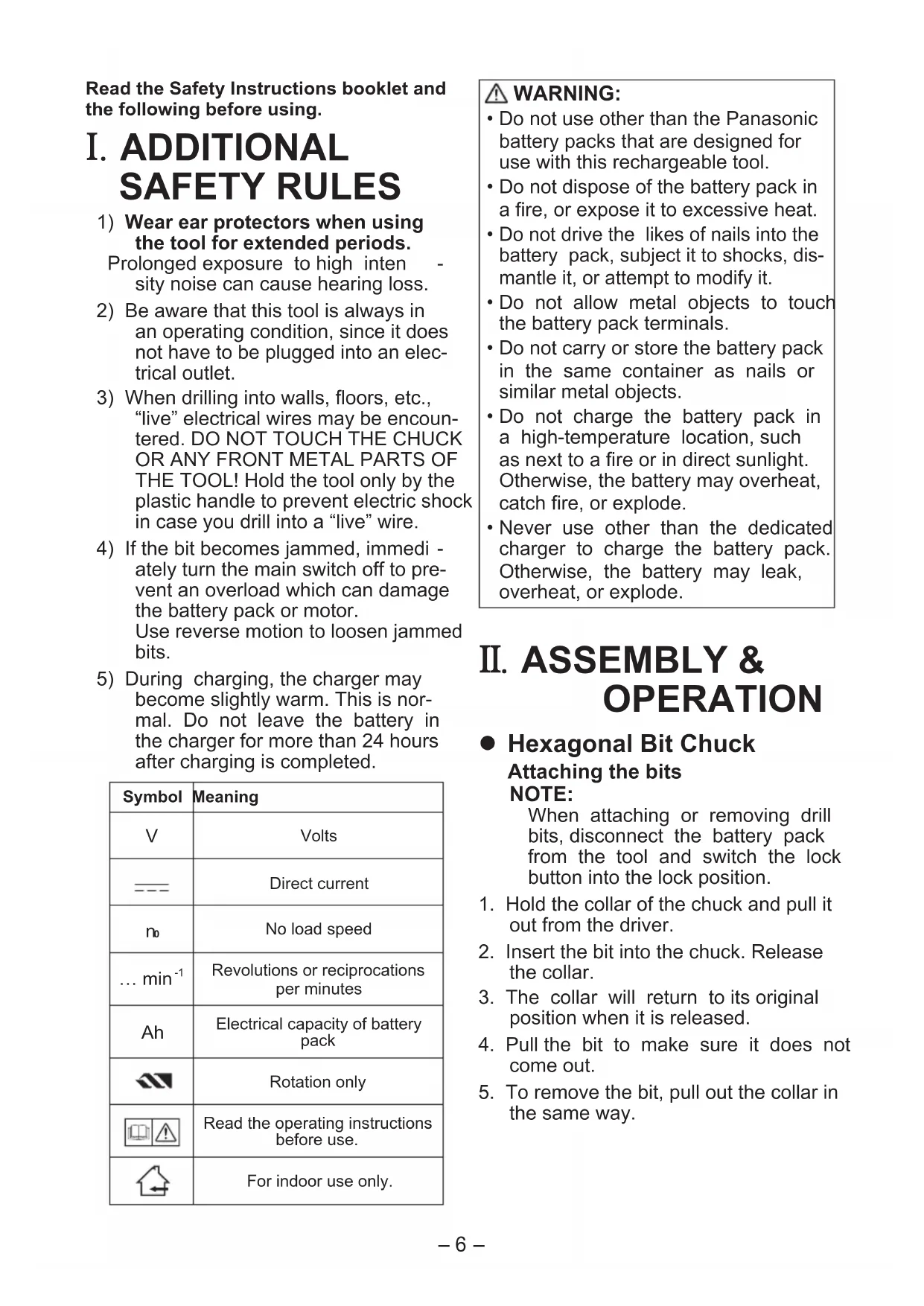
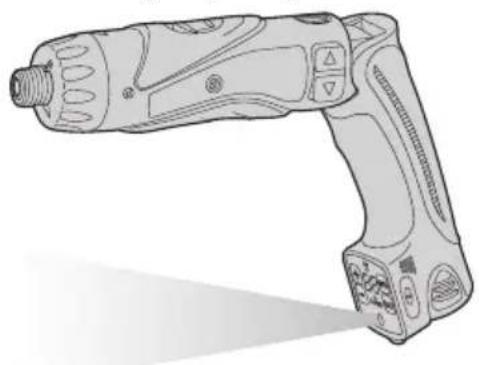
Cordless Drill & Driver
Akku-Bohrschrauber
AkkymyIaTOPHaIpeJIb-WhpyNoBepT
AkkymyTopHn npNb- WypynoBepT
Model No: EY7411
Before operating this unit, please read these instructions completely and save this manual for future use.
Read the Safety Instructions booklet and the following before using.
I. ADDITIONAL SAFETY RULES
1) Wear ear protectors when using the tool for extended periods.
Prolonged exposure to high intensity noise can cause hearing loss.
2) Be aware that this tool is always in an operating condition, since it does not have to be plugged into an electrical outlet.
3) When drilling into walls, floors, etc., "live" electrical wires may be encountered. DO NOT TOUCH THE CHUCK OR ANY FRONT METAL PARTS OF THE TOOL! Hold the tool only by the plastic handle to prevent electric shock in case you drill into a "live" wire.
4) If the bit becomes jammed, immediately turn the main switch off to prevent an overload which can damage the battery pack or motor. Use reverse motion to loosen jammed bits.
5) During charging, the charger may become slightly warm. This is normal. Do not leave the battery in the charger for more than 24 hours after charging is completed.
| Symbol | Meaning |
| V | Volts |
| --- | Direct current |
| no | No load speed |
| ... min-1 | Revolutions or reciprocations per minutes |
| Ah | Electrical capacity of battery pack |
| Rotation only | |
| Read the operating instructions before use. | |
| For indoor use only. |
WARNING:
- Do not use other than the Panasonic battery packs that are designed for use with this rechargeable tool.
- Do not dispose of the battery pack in a fire, or expose it to excessive heat.
- Do not drive the likes of nails into the battery pack, subject it to shocks, dismantle it, or attempt to modify it.
- Do not allow metal objects to touch the battery pack terminals.
- Do not carry or store the battery pack in the same container as nails or similar metal objects.
- Do not charge the battery pack in a high-temperature location, such as next to a fire or in direct sunlight. Otherwise, the battery may overheat, catch fire, or explode.
- Never use other than the dedicated charger to charge the battery pack. Otherwise, the battery may leak, overheat, or explode.
II. ASSEMBLY & OPERATION
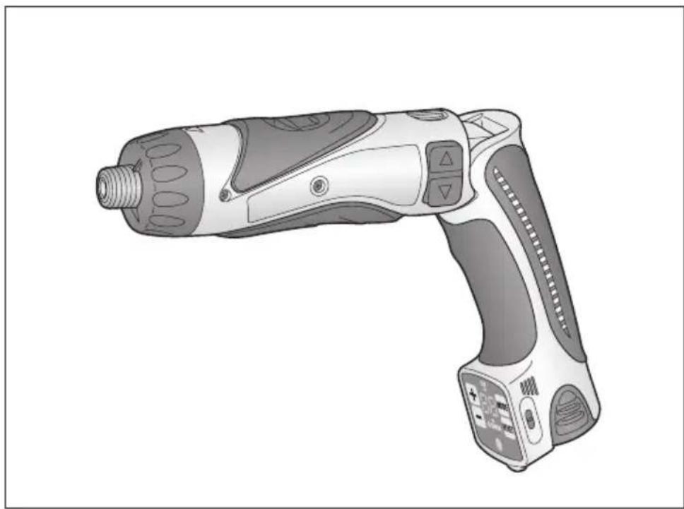
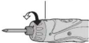
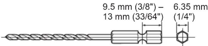
- Hexagonal Bit Chuck
Attaching the bits
NOTE:
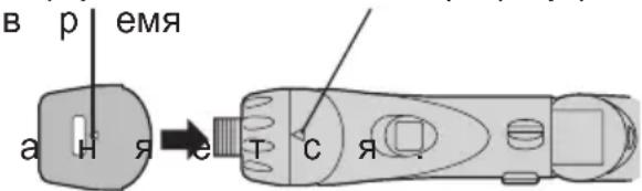
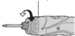
When attaching or removing drill bits, disconnect the battery pack from the tool and switch the lock button into the lock position.
- Hold the collar of the chuck and pull it out from the driver.
- Insert the bit into the chuck. Release the collar.
- The collar will return to its original position when it is released.
- Pull the bit to make sure it does not come out.
- To remove the bit, pull out the collar in the same way.
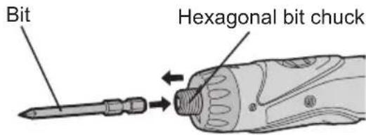
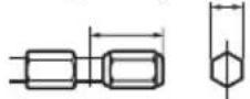
9.5 mm (3/8") - 13 mm (33/64") 6.35 mm (1/4")
- Clutch Handle (Clutch Torque Setting)
Adjust the torque to one of the 21 possible settings to the job. There is an interval of about 0.13N· m (1.3 kg-f-cm or 1.1 in-lbs) between steps.
CAUTION:
Test the setting before actual operation.
Set the scale at this mark.
Reference for Adjusting Torque
| Setting | Torque Use | |
| 1 | Approx: 0.29 N·m(3.0 kgf-cm or 2.6 in-lbs) | For driving screws |
| 5 | Approx: 0.82 N·m(8.4 kgf-cm or 7.3 in-lbs) | |
| 9 | Approx: 1.35 N·m(13.8 kgf-cm or 12.0 in-lbs) | |
| 13 | Approx: 1.88 N·m(19.2 kgf-cm or 16.6 in-lbs) | |
| 17 | Approx: 2.41 N·m(24.6 kgf-cm or 21.3 in-lbs) | |
| 21 | Approx: 2.94 N·m(30.0 kgf-cm or 26.0 in-lbs) | |
| Approx: 4.4 N·m(45.0 kgf-cm or 39.0 in-lbs$crews and drilling | For power-ful driving |
- When using at high speeds, set the clutch at 10 or below. (Operation stops at the maximum torque of 1.5 N·m (15 kgf·cm) when the scale is higher.)
- The auto shut-off function may become inoperable at high clutch settings when battery power drops. Recharge the battery in that case.
NOTE:
The chart is only a reference. The torque settings may differ by materials, types of screws, etc. Please test it at your own conditions before use.
Control Panel
Manufacturer settings upon shipment
- Count system: Count down system
- Count setting value: 99
- Buzzer sound pitch: b1 (Low sound)
- Double tightening counting prevention count time: 0 (OFF)
Hold switch: Released
Please set the settings according to conditions of use.
Screw count function
- Counts the number of auto stops. (Counts the number of screws driven)
The count method can be selected from "UP" or "DOWN". - When the set number of screws to be driven is reached, a buzzer sounds and the count value is reset.
The buzzer sound can be selected from 3 types of sound. - Double tightening counting prevention function
Work (double tightening and screw driving confirmation, etc.) that began within the set time is not counted after the driven screws are counted.
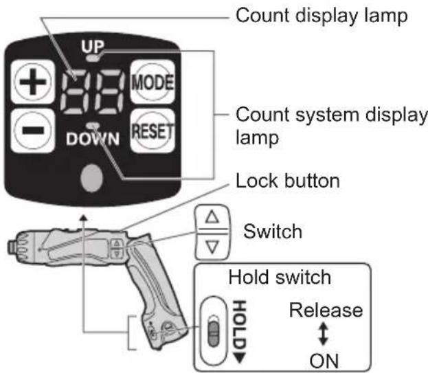
Starting the control panel
-
Release the hold switch.
-
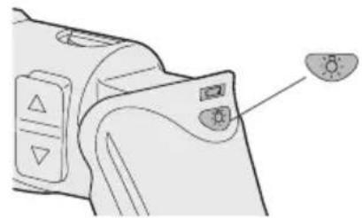
To illuminate the control panel
① Release the lock button
② Press Control panel is lit.)
- The count display lamp and "UP" or "DOWN" are illuminated.
Setting the count functions (Screw count setting/Count system setting)
- Press while the control panel is illuminated.
Each time is pressed, the screw count setting and count system setting switch and flash.
- Screw count setting Count display lamp flashes.
-
Count system setting "UP" or "DOWN" flashes.
-
Screw count setting
Set the number of screws with ^+ or
The range can be set within 0 - 99.
- 0 is not counted.
Count system setting
Press MODE. "UP" or "DOWN" will begin to flash. Next select "UP") or ("DOWN").
- Press and hold the (or) buttons while setting the torque to vary the value continuously.
< Count System "UP" > - Displays the count for the number of screws driven.
0→1→2...Set number
The settings are activated by pushing
- When the set number of screws is reached, the buzzer sounds and the count value resets to zero.
< Count System "DOWN" > - Displays the count for the remaining number of screws to be driven. (Set number)
- When the set number of screws to be driven is reached, the buzzer
sounds and the count value resets to original set number.
- The settings are activated by pushing
The previous setting will be cleared.
-
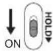
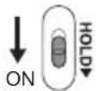
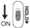
To prevent changes in the set values due to operational errors.
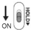
-
Turn the HOLD switch to ON.
Convenient function settings (buzzer sound setting/double tightening counting prevention time setting)
-
Press for 2 or more seconds while the control panel is illuminated.
-
Count display lamp "F1" is illuminated.
Each time is pressed, the buzzer sound setting and double tightening countering prevention time setting can be switched.
- "Buzzer sound setting" "F1" is illuminated.
-
"Double tightening counting prevention time setting" "F2" is illuminated.
-
Buzzer sound setting
The buzzer sound can be selected with when "F1" is illuminated.
| Operation | Display | Sound Frequency |
| + | b3 | High pitched sound (Approx. 4 kHz) |
| b2 | Medium pitched sound (Approx. 3 kHz) | |
| b1 | Low pitched sound (Approx. 2 kHz) | |
| b0 | No sound (OFF) |
- If reset is pressed, the buzzer sound saved from the previous setting is displayed.
Double tightening counting prevention time setting
Press MODE to illuminate "F2" and select the time with + -
| Operation | Display | No. of seconds | Following the screw count, screw driving within the set number of seconds is not counted. |
| 30 3 | seconds | ||
| : | : | ||
| 1 0.1 | second | ||
| 0 OFF | |||
-
If n is pressed, the time setting saved from the previous setting is displayed.
-
The settings are activated by pressing
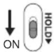
-
To prevent changes in the set values due to operational errors.
-
Turn the HOLD switch to ON.
To change the screw count while in use
- Release the hold switch.
-
Adjust the count value with + -
-
The displayed number of screws to be driven can be changed within the range of the screw count values.
-
To prevent changes in the set values due to operational errors.
-
Turn the HOLD switch to ON.
While setting, if no operations conducted for 60 or more seconds and when the battery is removed
Operation for the set value becomes invalid.
Please reset the operational values.
-
When batteries are changed while in use
-
When batteries are changed, the count value is saved. Therefore, the drill can be used continuously.
- Battery Low Warning Lamp
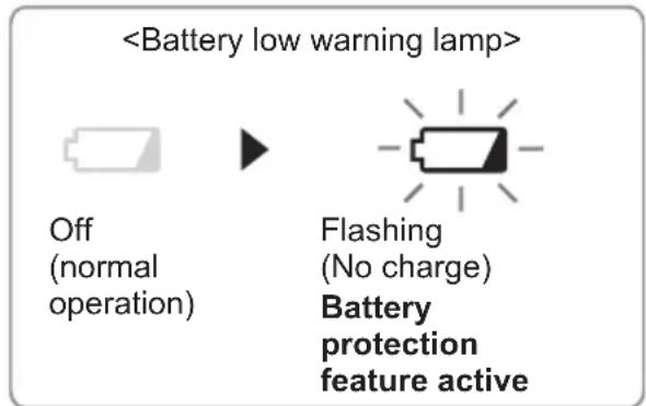
Excessive (complete) discharging of Li-ion batteries shortens their service life dramatically. The driver includes a battery protection feature designed to prevent excessive discharging of the battery pack.
- The battery protection feature activates immediately before the battery loses its charge, causing the battery low warning lamp to flash.
- If you notice the battery low, wait for the lamp flashing, charge the battery pack immediately.
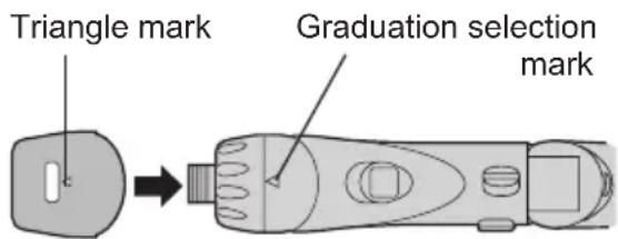
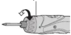
- Clutch Lock Cover
The clutch lock cover allows you to lock the clutch at the selected setting.
Attaching the cover
- Select the appropriate clutch setting for the application.
-
Attach the clutch lock cover.
-
Align the triangle mark on the cover with the graduation selection mark on the drill and attach.
Removing the cover
- Grip the clutch lock cover with your fingers on the mark and the bottom of the cover, then push in and twist to remove.
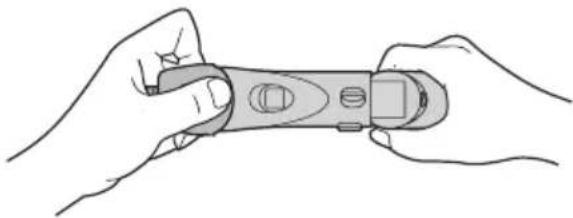
- It will be difficult to remove the clutch lock cover from the drill if you push on the side of the cover while pulling it off.
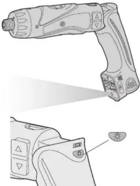
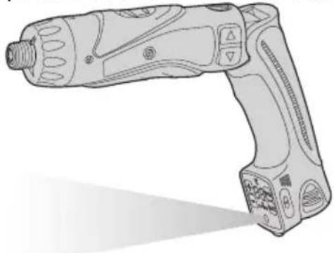
Using the LED Light
Before the use of LED light, always pull the power switch once.
Press the LED light on button.
The light illuminates with very low current, and it does not adversely affect the performance of the tool during use or its battery capacity.
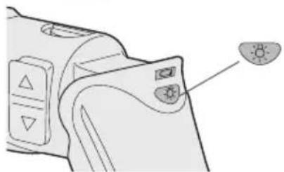
CAUTION:
-
The built-in LED light is designed to illuminate the small work area temporarily.
-
Do not use it as a substitute for a regular flashlight, since it does not have enough brightness.
-
LED light turns off when the tool has not been used for 5 minutes.
Caution:DO NOT STARE INTO BEAM.
Use of controls or adjustments or performance of procedures other than those specified herein may result in hazardous radiation exposure.
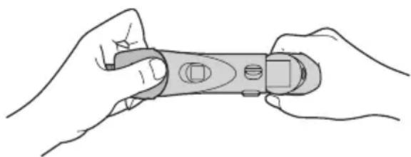
- Bit-locking Function
With the switch at off and the bit locked in place, the tool can be used as a manual screw-driver - up to 14.7 N·m (150 kgf·cm, 130 in-lbs).
There will be a little play in the driving shaft, but this is not a malfunction.
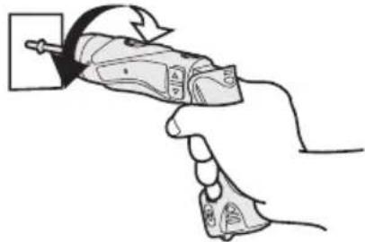
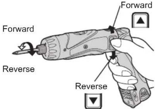
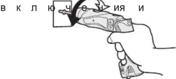
- Main Switch (ON/OFF)
Push the upper half of the switch for forward rotation, or the lower half for reverse rotation.
- Speed Selector Switch
To suit the application of this tool, two different rotational speeds are available. Depending upon use, either the high or low speed should be selected.
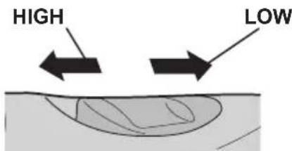
| Speed selection Torque | |
| LOW 200 min | -1 (rpm) High |
| HIGH 600 min | -1 (rpm) Low |
CAUTION:
- Check speed selector switch before use.
- Do not operate the speed selector
switch while the main switch is on (switch is in the ON position).
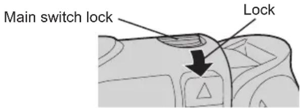
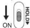
- Main Switch Lock
After use, set the main switch lock at the lock position to prevent accidental operation.
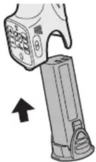
- Battery Pack (EY9L10)
- Remove the battery pack away from the tool.
- Charge the battery pack using the battery charger.
- After charging has been completed, remove the battery pack from the charger and connect it to the tool.
Disconnect the charger from the power source when not in use.
NOTE:
Use under extremely hot or cold conditions will reduce operating capacity per charge.
[Battery Pack]
For Appropriate Use of Battery pack
Li-ion Battery pack (EY9L10)
- For optimum battery life, store the Li-ion battery pack following use without charging it.
- The ambient temperature range is between 0^ (32^) and 40^ (104^) . If the battery pack is used when the battery temperature is below 0^
(32^) the tool may fail to function properly.
- When battery pack is not in use, keep it away from other metal objects like: paper clips, coins, keys, nails, screws, or other small metal objects that can make a connection from one terminal to another.
Shorting the battery terminals togethe er may cause sparks, burns or a fire. - When operating the battery pack, make sure the work place is well ventilated.
Battery Pack Life
The rechargeable batteries have a limited life. If the operation time becomes extremely short after recharging, replace the battery pack with a new one.
Battery Recycling
ATTENTION:
For environmental protection and recycling of materials, be sure that it is disposed of at an officially assigned location, if there is one in your country.
[Battery Charger]
Charging
Common Cautions for the Li-ion/Ni-Cd Battery Pack
NOTE:
- When a cold battery (of about 0^ or less) is to be charged in a warm room, leave the battery in the room for at least one hour and charge it when it has warmed up to room temperature. (Failing to do so may result in less than a full charge.)
Cool down the charger when charging more than two battery packs consecutively. - Do not insert your fingers into contact hole, when holding charger or any other occasions.
CAUTION:
To prevent the risk of fire or damage to the battery charger.
- Do not use power source from an engine generator.
- Do not cover vent holes on the charger and the battery pack.
- Unplug the charger when not in use.
Li-ion Battery Pack
NOTE:
Your battery pack is not fully charged at the time of purchase. Be sure to charge the battery before use.
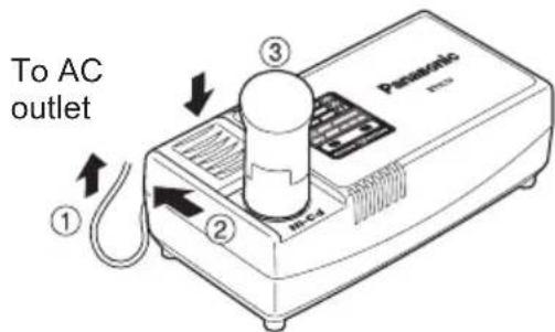
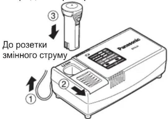
Battery charger (EY0L10)
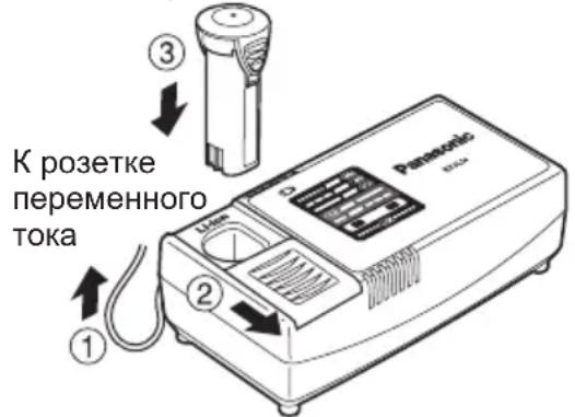
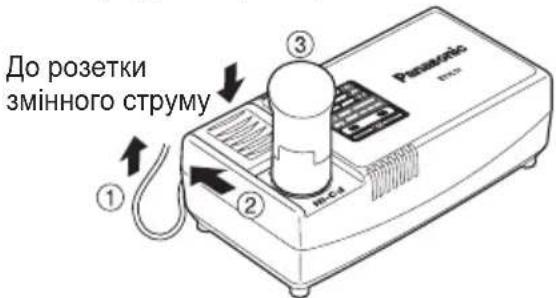
- Plug the charger into the AC outlet.
NOTE:
Sparks may be produced when the plug is inserted into the AC power supply, but this is not a problem in terms of safety.
-
Slide the battery dock cover back to allow insertion of the Li-ion battery pack.
-
Verify that the cover is locked, purely in place.
-
Insert the battery pack firmly into the charger.
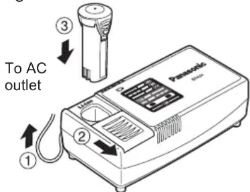
- During charging, the charging lamp will be lit.
When charging is completed, an internal electronic switch will automatically be triggered to prevent overcharging.
- Charging will not start if the battery pack is warm (for example, immediately after heavy-duty operation).
The orange standby lamp will be flashing until the battery cools down. Charging will then begin automatically.
-
The charge lamp (green) will flash slowly once the battery is approximately 80% charged.
-
When charging is completed, the charging lamp will start flashing quickly in green color.
- If the temperature of the battery pack is 0^ or less, charging takes longer to fully charge the battery pack than the standard charging time. Even when the battery is fully charged, it will have approximately 50% of the power of a fully charged battery at normal operating temperature.
- If the power lamp does not light immediately after the charger is plugged in, or if after the standard charging time the charging lamp does not flash quickly in green, consult an authorized dealer.
- If a fully charged battery pack is inserted into the charger again, the charging lamp lights up. After several minutes, the charging lamp may flash quickly to indicate the charging is completed.
Ni-Cd Battery Pack
NOTE:
When you charge the battery pack for the first time, or after prolonged storage, charge it for about 24 hours to bring the battery up to full capacity.
Battery charger (EY0L10)
- Plug the charger into the AC outlet.
NOTE:
Sparks may be produced when the plug is inserted into the AC power supply, but this is not a problem in terms of safety.
- Slide the battery dock cover back to allow insertion of the Ni-Cd battery pack.
- Verify that the cover is locked securely in place.
- Insert the battery pack firmly into the charger.
- During charging, the charging lamp will be lit.
When charging is completed, an internal electronic switch will automatically be triggered to prevent overcharging.
- Charging will not start if the battery pack is warm (for example, immediately after heavy-duty operation).
The orange standby lamp will be flashing until the battery cools down. Charging will then begin automatically.
- When charging is completed, the charging lamp will start flashing quickly in green color.
- If the power lamp does not light immediately after the charger is plugged in, or if after the standard charging time the charging lamp does not flash quickly in green, consult an authorized dealer.
- If a fully charged battery pack is inserted into the charger again, the charging lamp lights up. After several minutes, the charging lamp may flash quickly to indicate the charging is completed.
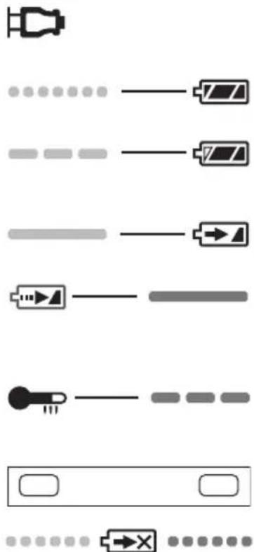
LAMP INDICATIONS

Green Lit
Charger is plugged into the AC outlet. Ready to charge.

Green Flashing Quickly
Charging is completed. (Full charge.)

Green Flashing
Battery is approximately 80% charged. (Usable charge. Li-ion only)

Green Lit
Now charging.

Orange Lit
Battery pack is cool.
The battery pack is being charged slowly to reduce the load on the battery. (Li-ion only)

Orange Flashing
Battery pack is warm. Charging will begin when temperature of battery pack drops.
Charging Status Lamp
Left: green Right: orange will be displayed.

Both Orange and Green Flashing Quickly
Charging is not possible. Clogged with dust or malfunction of the battery pack.
If the temperature of the battery pack is -10^ or less, the charging status lamp (orange) will also start flashing.
Charging will begin when the temperature of the battery pack goes up (Li-ion only)
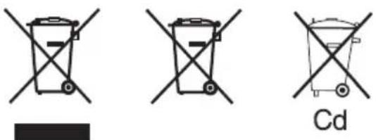
Information for Users on Collection and Disposal of Old Equipment and used Batteries
These symbols on the products, packaging, and/or accompanying documents mean that used electrical and electronic products and batteries should not be mixed with general household waste.
For proper treatment, recovery and recycling of old products and used batteries, please take them to applicable collection points, in accordance with your national legislation and the Directives 2002/96/EC and 2006/66/EC.
By disposing of these products and batteries correctly, you will help to save valuable resources and prevent any potential negative effects on human health and the environment which could otherwise arise from inappropriate waste handling.
For more information about collection and recycling of old products and batteries, please contact your local municipality, your waste disposal service or the point of sale where you purchased the items.
Penalties may be applicable for incorrect disposal of this waste, in accordance with national legislation.
For business users in the European Union
If you wish to discard electrical and electronic equipment, please contact your dealer or supplier for further information.
[Information on Disposal in other Countries outside the European Union]
These symbols are only valid in the European Union. If you wish to discard these items, please contact your local authorities or dealer and ask for the correct method of disposal.
Note for the battery symbol (bottom two symbol examples):
This symbol might be used in combination with a chemical symbol. In this case it complies with the requirement set by the Directive for the chemical involved.
III. MAINTENANCE
Use only a dry, soft cloth for wiping the unit. Do not use a damp cloth, thinner, benzine, or other volatile solvents for cleaning.
IV. ACCESSORIES
CAUTION:
To prevent the risk of injury, only use accessory or attachment for its stated purpose.
If you need any assistance for more details regarding these accessories, ask your local service center.
- EY9X007E
Clutch lock cover
Use only bits suitable for size of drill's chuck.
V. SPECIFICATIONS
MAIN UNIT
| Model EY7411 | |||
| Capacity | Screw driving | Machine screw M2.5 - M5 | |
| Wood screw ø 3.8 × 38 mm (5/32 " × 1-29/64") | |||
| Drilling For metal | tal ø 5 mm (13/64) | ") spc t = 1.6 mm | |
| Motor 3.6 V DC | |||
| No load speed | LOW: 200 min-1 (rpm) | ||
| HIGH: 600 min-1 (rpm) | |||
| Maximum torque | LOW: 4.4 N·m (45 kgf-cm, 39 in-lbs) HIGH: 1.5 N·m (15 kgf-cm, 13 in-lbs) | ||
| Maximum clutch torque 3.0 N·m | (30 kgf-cm, 26 in-lbs) | ||
| Overall length 283 mm (11-5/32) | ") | ||
| Weight (with battery pack) 0.5 kg (1.1 lbs) | |||
BATTERY PACK
| Model EY9L10 | |
| Storage battery Li-ion Battery | |
| Battery voltage | 3.6 V DC (3.6 V × 1 cell) |
| Capacity | 1.5 Ah |
BATTERY CHARGER
| Model EY0L10 | |||
| Weight | 0.6 kg (1.3 lbs) | ||
| Electrical rating | See the rating plate on the bottom of the charger. | ||
| Charging time | 2.4 V | 3.6 V | |
| 1.2 Ah | EY9021 | EY9025 | |
| Full: 15 min. | Full: 15 min. | ||
| 1.5 Ah | EY9L10 | ||
| Usable: 15 min. | |||
| Full: 30 min. | |||
NOTE:
- For applicable battery packs to this charger, see the label on the charger or the latest general catalog.
The instruction label on the battery packs also shows the applicable charger.
ONLY FOR U. K.
VI. ELECTRICAL PLUG INFORMATION
FOR YOUR SAFETY PLEASE READ THE FOLLOWING TEXT CAREFULLY
This appliance is supplied with a moulded three pin mains plug for your safety and convenience.
A 5 amp fuse is fitted in this plug.
Should the fuse need to be replaced please ensure that the replacement fuse has a rating of 5 amp and that it is approved by ASTA or BSI to BS1362.
Check for the ASTA mark or the BSI mark on the body of the fuse.
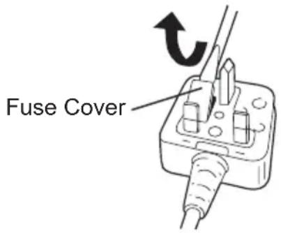
If the plug contains a removable fuse cover you must ensure that it is refitted when the fuse is replaced.
If you lose the fuse cover the plug must not be used until a replacement cover is obtained.
A replacement fuse cover can purchased from your local Panasonic Dealer.
IF THE FITTED MOULDED PLUG IS UNSUITABLE FOR THE SOCKET OUTLET IN YOUR HOME THEN THE FUSE SHOULD BE REMOVED AND THE PLUG CUT OFF AND DISPOSED OF SAFELY. THERE IS A DANGER OF SEVERE ELECTRICAL SHOCK IF THE CUT OFF PLUG IS INSERTED INTO ANY 13 AMP SOCKET.
If a new plug is to be fitted please observe the wiring code as shown below.
If in any doubt please consult a qualified electrician.
IMPORTANT:
The wires in this mains lead are coloured in accordance with the following code:
Blue: Neutral
Brown:Live
As the colours of the wire in the mains lead of this appliance may not correspond with the coloured markings identifying the terminals in your plug, proceed as follows. The wire which is coloured BLUE must be connected to the terminal in the plug which is marked with the letter N or coloured BLACK.
The wire which is coloured BROWN must be connected to the terminal in the plug which is marked with the letter L or coloured RED.
Under no circumstances should either of these wires be connected to the earth terminal of the three pin plug, marked with the letter E or the Earth Symbol 1一
How to replace the fuse: Open the fuse compartment with a screwdriver and b e replace the fuse and fuse cover if it is removable.
This apparatus was produced to BS800.
Pacco battery Li-ion
NOTA:
| Bediening | Display T | bonfrequentie |
| +↑ | b3 | Hoge toon(ong. 4 kHz) |
| b2 | Middentoon(ong. 3 kHz) | |
| b1 | Lage toon(ong. 2 kHz) | |
| b0 | Geen toon (UIT) |
- Interruptor principal (ON/OFF)
PykoTka MyΦTbI (YcTaHOBka KpyTЯоero MOMeHTa MΦTbI)
YcTaHOBnTe Heo6XoDnMbI JIpa6Otbl KpyTz uN MO MeHT B OJHO 3 BO3MOxHbIX 3NaueHn. MeKdy HmN cyuectByeT INTEpBaI npImepHo B 0,13 H·M (1,3 Krc-cM).
BHIMAHNE:
IpoBepbTe yCTaHOBky nepeD HacToaue pa60toi.
YCTAHOBITE ⅢKaJIy BO3JIe 3TOI MEtKn.
PeKOMeHdaaun dJa HaCTpoiKn KpyTJ- Uero MOMeHTa
| Знachievements | Крочи моремт | Искобъовиме |
| 1 | Проблиз.: 0,29 H·M(3,0 кгс-cм) | ДляЗавинувaningшушив |
| 5 | Проблиз.: 0,82 H·M(8,4 кгс-cм) | |
| 9 | Проблиз.: 1,35 H·M(13,8 кгс-cm) | |
| 13 | Проблиз.: 1,88 H·M(19,2 кгс-cm) | |
| 17 | Проблиз.: 2,41 H·M(24,6 кгс-cm) | |
| 21 | Проблиз.: 2,94 H·M(30,0 кгс-cm) | |
| Проблиз.: 4,4 Hm(45,0 кгс-cm) | Для сильноюзавин Bavaningшушиви Сберлесия |
- Пр И спОЛьЗВаHи Ha BbICOKnx
CKOPOCTaX yCTaHOBnTe 3HaueHne
КpyТЯШERO MOME H Ta MyФТ bI
ПОLOЖЕНe 10 nII nHKe. (Pa6To
пpeKpaшaETcЯ пrMaKcIMaJIbHOM
КpyТЯШЕМOMeHTe 1,5 H·M (15
КRC-CM), ecn YcTAHOBNeHо 6OJIee
БblICOKOE 3HaueHne).
-Функця abTOMaTnueCKOTO OTKIO-уеня MOKeT CTaTB He3ofoKeTKBHOI npN IcNoJIb3OBAHnHa BbICOKX 3Ha-уенyx KpyTJUeRO MOMeHTa MyfTbI, ecn 3apd 6aTapeu CHn3ntc. B TAKOM Cnyae 3apdnte 6aTapeo.
ПОНМЕЧАНЕ:
Данна ТабпuaяВлЯETСТОльko peKOMeHdaци. 3наченue yCTa-HOBKN KpyTЯшero MOMeHTa MoXeT OTПУЧТСВ B 3aBNCIMOCTN OT MaTePnANoB, TINOB shypynOB nT.n. Пожалуйста, npobepbTe erO B co6CTBeHHbIX ycN OBnIx nepeД nCNoJIb3OBaHHeM.
HnDnKaTOp DnCnJpe NOdCheta nHn K aTOpBUP" Hn "DOWN"3ayopaoBCo BnMn
Ha cTpoNka yHKnI nOdcyea (HaCtpoNka noDCyeta wypynOB/ HaCTPONka CNCTeMbI NOcYeTa) KOJI NUYEcT TB O
x1.HaKMTeT KHOHky O nepeKIOHeHnpeKIMOB paObToI MODE npu CBETaueenca naHeN ynpabJeHn
KaKdbi pa3 npn HaxkTu KHOKN HOCTPOKA NOCheta WypynOB HAcTPOKA CNCTeMbI NOCheta BKIOUaOTcN MIRaOT
HacpoKa noDceta wypnoB
0 B NnKaop O Dnpey noDceta Muraet.
Hactpoika cnCTembl noDcyeTa INndkaTopbl "UP" nIIN "DOWN" MnraHT.
a YcTaHOBnTe T KGNuueCTBOa WypynOBKHOKNo+nn
-Диана3OH MOXET 6bITb yCTaHOBJIeH B npedenax oT0do99.
- Ye yuHTbBaetc
Hactpoia cntembl nocheta
HaxmTe KhONky MODE. HndkaTopbI "UP" nnn "DOWN" NaHyT MnraTb. 3aTeM Bbl6epnte HanpaBJIeHne NODcYeTa KhoNkamn (^+ ("UP") nnn - ("DOWN")
HaKmTe ydepxnBaIe KHONKn ()nn npu yc TaHOBKe kpyTaeo MOMeHTa dna NOCTOHHORO n3MeHeHn 3HaueHn
< CnCTema noDcyeTa "UP">
- OTo6paKaJaTcra NOpCHeT KOJIuYeCTBa 3aBepHyTbIX WypynOB.
(0→1→2...YCTaHOBneHHoe KOJIINueCTBO
HacTpoNka aKTHBnpyeTcra HaxKaTNEm KHOPIK
- Pnp DoCTNKeHn yCTaHOBJIeHHORO KOINueCTBa WypynOB, BKIOUcaETcra 3ByKOBOn CnH NOIDCHNTAHHOe 3NaueHne O6HyJAreTc
< CnucTeMa nOndcYeTa“DOWN”> - OTo6paJxAeTcnoDcHET OCTaBweroCkOJIuYeCTBa WypynOB, KOToPbIe Heo6xoJMo 3aBepHyTb. (YCTaHOBJIeHHoe KOnIyEcTBo.. 2→1→0)
-
Прдостинжиуctановнello КолчесТВа WypynOB, KOTOpbIe HeobxOДIMо 3aBepHyTb, BKNIOuaETcR 3ByKOBOI CnHaN I NOdCHTaHHOE 3Haue Hne c6p acbl NepBOHaayalbHo yCTaHOBNeHHORO KOLNUYeCTBa.
-
HactpoKa aKTHBnpyetcHaxaTneM KHOKN
-
PpeBbIyua HacTpoKa 6ydet OuHSeHa.
4.ДЯ npedeOTbpaueHnI N3MeHeHnYCTaHOBJIeHHbIX 3HaueHn B CBra3N COuIN6kAmn B pa6oTe.
- YcTaHOBnTe BkIIOuAteJIb 6JIOKInpOBKn HOLD B noJIOKeHne ON.
HacrpoynuO6HbIXyHKn(HacrpoNka 3BykoBOro cnHaJa/ HacrpoNka BpeMeHn PpeDToBpaueHnnoDcYeTa npn DBOHOn 3aTJxke)
-
Haxmte KhONky udepKnBaIte ee B TeueHne 2-x nnn 6oJee cekyH npn CBetTaeCnnaHeN ynpaBHeHn
-
Иndикатор диспег посчета "F1" 3aropaetca
KaKdbi pa3 npn HaxkTmN KHOKN MODE MOryT BKnHouaTbCn HAcTPOkKa 3ByKOBOrO CNHaJa N HAcTPOkKa BpeMeHn PpeDcTbPaUeHn NOcYeTa npn DBOHOn 3aTJXKe
-
"Hactpoika 3BykoBOrO cRHaJa → 3aropaeTcNHNdkaTop "F1."
“HactpoKa BpeMeH npedotBpaueHn Ioceta pni DBOHO 3aTgKe 3aropaeTc nHdkaTopF2". -
Hac troponka 3BykoBoro cnHaJa
3ByKOBoI CNHaJI MOxHO BbIbnpaTb C NOMOuBIO + -, KOrDa BBICBeYNBaeTcA INHdkaTop "F1"
KpbIshka 6JIOKINPOBKN MyΦTbI
KpbIuKa 6nOKnPOBKn MyΦTbI N03BOJAreT BAm 3a 6n O K n P o B aT Bbl6paHHoH hAcTpOoiKe.
PpncoeHHeHne KpbIuKn
- B bI 6e pN Te C O OT Betc T NaCTpOiKN MyΦTbI B 3aBnCmOCTn OT npIMHeHn
- PpncoeHnHTe KpbIuKy 6JIOKIpOBKn MycTbI
CoBmecHTe TpeyroJIbHbI 3HaK Ha KpbIuKe CO 3HaKOM BbI6Opa rpaD y npOB Kn H npncOeHNHTe
TpeyrolbHb3HaK 3HaK BbI6opa rpaDympoBKn
CHaTne KpbIuKn
- Haxmnte nalbuaHn Ha Tpeyrolhbln 3HaK △ Ha KpbIuKe 6JOKUPOBKn MyΦTbI N Ha HNXHIOU YacTb KpbIuKn, a 3aTeM NOTAHTE IN NOBepHNTe DJIa CHrTna
- Bydet TaeKeNo CHaTb KpbIuKy 6noknpOBKn MyoTbI C dpeN,ecnBb I HaxmaeTe Ondy CTOpOHy KpbIuKn npie ee ChrTIN
- Исторьанец CBeToДноДноюпогCBETКИ
Bcerda HaxmMaTe nepeKJIouaTeJb nI T a H I y O d N H nCNoIb3OBA H IeM CBeToDnOdHO NODCBETKn.
H aЖ M N Te K H O N K y BbIKJIHcHEny CBETOДNODHOI NOCDBETKn
IocBcTeKa rOpNT npn OueHb Hn3KOM TOke n He OKa3bIBaET He6NaIarOpnpyTHoro BO3dienCTBnHa npOn3BOIDnteNbHOCTb IHCTpyMeHTa BO Bpempa60TbI nnHa eMKoCTb erO 6atapen.
BHIMAHNE:
BCTpoEHnA CBeToOnoHnA NOcCBetKa npedHa3HaueHa DnBpeMeHHoro OCBeueHn He6OJbWOn pa6Oey 30Hbl.
He nCnoJb3yIe ee B KaueCTBe 3aMeHbI NOCTOHHoro fOHApNka, TAK KAK OHa He Oblaadaet DOCTaTOUHO JRPKoCTbIO.
-ECNINHCTpyMeHT He NCNOJb3yeTcB TeueHne 5 MNHyT, CBETOIOHOHa NOCBETKa BbIKIQUHTcR.
BHHMaHHe:HE CMOTPETb HA JIyU.
IcnoJIb3OBAHne opraHOB ynpaBHeHn Iy nperyIpOBOK, NIO BO BbINOJIHeHne IpOceDyp INbIM O6pa3OM, Yem yka3aHO B DaHHo INHCTpyKcUN, MOKeT pINBeCTN K nonaHaHIO NOB Bo3DeiCTBHe ONaCHOr N3JLyHeHn.
-ФункцяблOKирOBн haCaДКn
C BbIKIIOyeHHbIM NepeKJIIOyATEJEM 3aΦNKcnpOBaHHoH MaTe HacaIKoN-
OTBepTKO, DaHHbIN HNCTpyMeHT MOKeT
NCNoJIb3OBaTbcB B KaueCTBe pyHOn
OTBepTKI Do 14,7 H·M (150 Krc-cM).
B NaTPOHe 6yDeT npCytCTBOBaTb
He6BJIbShoEeHooT, To He RaJIaETcR
HEncnPaBHOCTbIO.
- Ecni 6aTapeiHbI 6nok He nCnoJIb3y-etc, xpaHnte erO noJaIbIe OT TaKINxMetaJIInuecknx IpeMToB, KaK CKePENKMOHeTbl, KInouN, TBO3DN, UpyNbI, INJ INpyNX MeIKNX MetaJIInueckNX
c PpeMToB, KOTOpbIe MOrY T pINBeCTN K KOHTaKTo OndHOr KNeMMbI C dpyrOi.
XpaHeHne 6aTapeeHbIX 6JOKOB BMeCTe MOxET CTaTB INpUHHOu BO3HNKHOBeHn ICKP, OKOROB NIN NOKapa.
-BoBpempaobtbc6aTapeHbIM6IOKOM y6eNTecb,yTO paOoee nOmeueHne xopoio npOBetpnaeTcra.
Cpok cIyX6bI 6aTapeHoro 6Joka
AkkymyIaTOPbIe 6aTapeH ImeOT orpaHnueHHbI CpOK cnyK6bl. EcIn nocJe3apdKn BpeM aYHKcIOHnpOBaHnCTaHOBHTcay Ype3MePHO KOpOTkIM, 3aMeHnTe 6aTapeHbI 6lOK Ha HObI.
YtJn3aun6aTapeu BHIMAHNE
B ueJx 3aunTbI OKpykaOuSei cpebl I yTuIN3aUIM MaTePnAIOB, y6eINTEcB, UTO OHa yTuIN3InPOBaHa B OOnuJaNbHO npEHa3NaueHHom MeCTe, ecJI NaKOBbIe eCTb B BaWei cTpaHe.
[3apяДhoe yctpoIcTBO]
3apяdka
Оьше МерыпpeДOCToPOxHocTn ДЯ ЛNTи-NOHOrO/HNKeJIb- KaДМиEBOrO 6aTaapeHOrO 6JOKa ПРИМЕЧАНЕ
-Призарядкхолоногбатарног
6лoka (c Temператури Нжke 0°C (32°F))В ТЕNTOM MeCTe, OCTabbTe 6atapeHbI
6LOK B 3TOM MeCTe И NOДОЖДITE 6OJee
ODHORO Yaca, NOKa 6atapeЯ Harpeetc
do урOBHЯ Temператypbl OkpykaIOUsei
CpeDbI. B npOTINBHom clyuae, 6atapeHbI
6LOK MoXeT He 3apAITTCa ПОЛHOCtBu.
- Oxlahtié 3apádHoe yctpOcTBO npi nocleIDobateJbHOJ 3apjKe 6oJee Yem DByx 6aTapeHbIX 6JOKOB.
He BCTabJnTe Baun naIbU bKOHTaKTHbIe OTBepCTN, KOrDa Bbldepxnte 3apAnHOe yctpOInCTBO,a TaKKe B Dpynx CnyuaX.
BHIMAHNE:
IЯ npedotbpaueHn pncKa noXapa nIIN NOBpeKdEHHa 3apAaHOrO yctpoNCTBa.
He nCnoJb3yIte B kaueCTBe nCTOuHnka nHTaHn reHepaTOp DniratJIa.
He 6IOKpynte BEHTnJIaCIOHHbIE OTBepCTnHa 3apAnHOM yCTpOINCTBE n 6aTapeHOM 6nKe.
- BbIKHouHTe 3apAHOe yCTpoiCTBO n3 WTeNCeJIbHOJ PO3ETKN, ecn OHO He NCPOJIb3yETcR.
Лntи-нонь 6aTapeHbI 6JOK
ПРИМЕЧАНЕ:
Baw 6aTapeHbI 6JOK He YBJIeTCa NOJHOCTbIO 3apXKeHHbIM BO BpeMnOKynK. He 3abYbTe 3apAnTb erO nepeNcNoJIb3OBaHNem.
3apndHoe yctpoinCTBO(ey0L10)
- BknHouHte 3apAidHoe yCTpoiCTBO B wTeNceIbHyO p03eTKy nepemEHHO TOKa.
ПРИМЕЧАНЕ:
IpnnoKIOUeHn WTeNCEbHOB BNIK K NCTOCHNY NITaHNApeMeHHORo TOKAMORYT NOBtBCRAckpbI,HO3TO He npedctablaet npo6nemy c TOnkN 3peHn8Be30NaCHOCTN.
2.CdBnHbTe Ha3ad KpbIuKy yrny6neHnA J7 6aTapeN, YTO6bI BCTaBNTb JNTnHIOHHb6aTapeeHb6KnK.
-
Y6eIITecb, yTO KpbIuKa HaJeXHO 3aФИKcnpOBAHa Ha MeCTe.
-
ПлOTнО BCTaBbTe 6aTapeинБИ 6ЛOKВ 3apAДHoe yCTpoIcTBO.
4.BoBpeM3apAdkn6ydeT ropeTb lamnoKa 3apAdkn.
IocJe 3aBepWeHn 3apAKn aBTOMaTHueckn cpa6Otae BHyTpEHHN 3JIeKTPoHNbI NepeKIIouaTeJb, PpeDoTbPaUaaype3MePhyU 3apAky.
3apKa HnH 6aTapeHbIbIcNtKOMrOpaH (HaPIMep,HeNocpeDCTBENHO nocne yHKUHOHPOBaHn np 6oJbwoi Harpy3Ke).
OpaHkeBaJ lamnoUka pexnma Oxu-daHn8 budet Mrratb, noka baTapey He OCTbIHET.
3aTeM 3apJaKa HaUHeTcA ABTomATn-ueCKn.
-
Ламночka 3apяdkn (3eileha) 6ydet MeДлЕнHо MИraTb, КАТольКо 6aTapeя 6ydet 3apяжehа прIMepHo Ha 80%.
-
После 3авершени зардку Namnoчka 3ардки нанет бicitpo Mngar TB 3eHbIM CBETOM.
-
Ecni TemnepaTypa 6atapeHoro 6noka coCTabJareT 0^ nIIM MeHbSe, NOHa3apJaKa 6atapeHoro 6noka 3aMTe 6oJIbWe BpeMeH, Yem ObbyHoe BpeMa 3apJdKn.
TpnbAIN BnINB Wymy BnCOKoi iHTeHCNBHOCTi MOKe np3BeCTn Do BtpaTN Cnyx.
2) Pam'yaTae, lo daHn iHcTpymeHT 3aBXd n nepe6yBa e y po6oOmy cTaHi, ockiNbKn Ioro He Tpe6a BMnKaTu B eJeKtpnHy p03eTKy.
3)П рс CBe рд Ли Н i OT BO 3aRbHcYBaHHi wypyniB BCEpeDnHy CTIN,пДнor iT.i. IHCTpymeHT moKe ДОТОРКНУТСЯ npOBODIB,якпpe6yBaIOTB nID Ha npу roю . H E TO PK A IWECT N IPAH HOFO NAT PO H W B IN K O T P N E A TAKOXK ByDb-ЯKIX INIUX X PEPeDHIX METAJIEBXX DETAJIEN IHCTPymEHTY! Jkso Bu 3aRbH- cyte wypyn abo 3a6nBaTe noro BCEpeDInHy npOBODY, zuo 3haxOJTbcr nID HanpyroTO, 3 MeTOU 3anobirHHa ypaJxHnEJeKTPnUHM CTPymOM TrpmaTe IHCTpymeHT nIwe 3a ПлacTMacoBY pyKOATky.
4) YKuo HacaKa 6yna 3aTnchyta, HeraHOBuMKHITb rOJOBHn BUMNKa3 MeTOO 3anobirAHn nepeHaBaHTaKeHHa, 0 MoXe N0WKoDHTN 6batapeHn 6Iok a60 MOTop. IINBIBInbHeHHa HacADOK, 0 3aknnHNINc BIKOPNCOTByTe peBepCnBHn pyx.
5)Пдчac3apdxeHn3apdHnpictpiMожe3JIerkaHarpiTncb.ZeHopMaIbHm.He 3aIIuwaIte6atapeyo3apdHomy npicctpoi6Inbwe HIX Ha24 roDHH nic3aBepseHn3apdKn.
6) InΦopMaiaJ ΜΟДΟ TePmHγ Cnyx6n (npndaTHocti) BcTaHOBJIeHm BnO6HnKOM TepmH Cnyx6n (npndaTHocTi) ΚbOro BnO6y DopIBHIOE 7 pOKaM 3 DaTn BnTOBJIeHHa 3a yMOBn, ΜΟ BnPiδ BnKOpNCToByεTbcA
y cybopi BIDNOBIDHOCTI DO DIINCHOI INCTpykii 3 ekCnnyatau TaTexHnX CTaHdapti, 0o 3actOCOByIOTBcA Do UboR Bnp6y.
Tepmin cnyk6b6aTapeHnx 6IokIBopBHOe:5003aprKaam (TINbKN DnI HikeNb-KaMIEBOrO 6aTaapeHoro 6IOKy),12003aprKaAM (TINbKn DnI HikeNb-Metan-riDpNHOrO 6aTaapeHoro 6IOKy)3 DaTN BnPo6HnCTBa 3a TNX CAMNX yMOB.
Panaconik EneKtpnk Bopkc Ko., TtOcaka, YnoHia
He BnKOpNCToBnyTe iHsi 6aTapeHi 6I O K N, Kp I M 6I O K I B F np3HaueHnx DJIg BnKOpNCtAHNRA 3 CIm AkymyJIaTOPHM IHCTpyMeHTOM.
He KnaDiTb 6aTapeHn6NOK y BoroHb i He NiDaBaTe NOro BnNBy BnCokoi TemepaTypu.
- He BCTaBJaIe Tbe 6aTapeHnHbLOK TaKi npEmdTe, Jk rBi3dkn, He NiDaBaJte IyDapam, He po3bpaIte NOrO i He HamaraItecBnuO3MInHTN.
He donyckaTe TopkaHnMaTaIiHuNX npedmetIB Do KneM 6aTapeHoro 6noka
He nepenocitb i He 36epiraute 6atapeHnB ODHMy Ruky 3B i 3d Ka Ma Mna 6o a H a MetaniiHmN npedMeTaMn.
He 3apjkaTe 6aTapeHn 6lok y Micci 3 BUCOKO TO Tempeatypo, HapniklaD, nopA3 3 Borhem a6o nI npMIM COHAYHMN IpOMeHAM. Ihakwe 6aTape MoKe neperpitnc, 3aHHTNC a6o BN6yXHyTN.
Hi B ykomy Bu npaKy He BnKOpncTOBynte 3apRKn 6bTapeHoro 6noka iHwni 3apAHH npncTpi, Kpim CneuaHbHO npn3HaueHoro Dnra CbOro npncTPOH. I Na K W e 6at a p e J npotikatn, neperpitncs a6o Bn6yxHyTN.
II. 3БIPKA TA ФУнкциОHyBAHHЯ
PykoTka MyΦTn (BcTaHOBJIeHHa KpyTnIbHOro MOMeHTy MyΦTn)
BctaHOBIb Heo6xIDHn Dn pO6OTn KpyTINbHm MOMeHT B OJHe 321 MoKJIbNX 3NaueHb. Mix HmN icHy e iTHepBaI np6ln3Ho y 0,13 H·M (1,3 Krc-cM).
YBAGA:
Ipebeipte yctaHObky nepeid cnpaBXH- 0IO p600TOIO a Tn
BctaHOBIb 6kany 6iI niEi MiTKn.
Pekomendaqui nHaanawTyBaHHKpyTINbHOro MOMeHTy
HactpoNn Bnpo6nka npn noctaayHHi
- Cnctema πiDpaxyHky: 3BOpOTHi Haprrm πiDpaxyHky
BcTaHOBJIeHe 3HaueHnI npaxyHKy: 99
Bucota ToHy 3ByKOBOrO cnHany: b1 (Tnxn 3ByK) - Yac Dnna noDbiHoro 3aTaryBaHHra, Uo He BpaxOByeTbcra npn iDpaxyHky KInbKocTi wypynib:0(OFF)
Bmkauch 6IOKyBaHHa: BmKHeHO Bydb Iacka, BCTaHObitb HAcTpoKn BiIDNOiDHO Do yMOB BNKOpNCtAHHra.
- "Hactpoika 3BykoBOrO cnHaNy" → cnaIaxye iHdnkaTOp "F1".
"HacrpoKa yacy dny noDbinHro 3aTaryBaHHy, IIO He BpaxOByeTbcra" cnaIaxye INdkaTop "F2".
2.HactpoJa 3BykoBOrO cnHaJIy
3BykoBn CnHaN MoXHa Bn6npaTn 3 DOnOMoROO+ KOJI N CBiTbCra IHdkaTOp "F1".
HacrpoKa yacy dny noDbiHoro 3aTayBaHHa, 0 He BpaxOByETbcra
HaTnCHiTB KHONKy 3aogpHHiaHnKaTopa F2" i Bn6epiB yac KHOKNkAMN
3.HaCtpoKn BCTaHOBIOHOTbcHaTNCHEHHKM HONK
4.ДЯ 3anobiraHHra3MiHaB BCTaHOBneHnX 3HaueHb y 3B'ra3ky 3 NOMINkamn B po60ti.
BcTa HO BiTb BMNK aq 6JIOkyBaHHa HOLD B noJIOxehn ON.
3miHa nipaxyHky wypyniB niD yac po6oTu
- Bumkhitb 6IokyBaHHa.
2.BiDperyIIOIte paxyHKOBe 3HaueHHKHOKNAMn
BidobpaxeHa KINbKicTb WypyniB, 0oPiIJIraIOTb 3akpyyBaHHIO, MoKe6ytn 3MiHeHa B Mexax 3HaueHbPiDpaXyHky WypyniB.
3.ДЯЗANO6iraHнЯ 3MiHaM BCTaHOBNeHIX 3NaueHb y 3B'ra3ky 3 NOMIJKamn Bpo6OtI.
BcTaHOBIb BMnKaU 6JOKyBaHHH HOLD B noJoxeHH ON.
■ПиНастpoиi,якso HЯкiДiI He npobodaybcs npotrayom 60 cekyHd a6o 6inbwe,i npu 3nAtiбatapei
- Onepaizj IJI Y BCTAH OBJeHOro 3HaueHHr CTae HeiIChOIO. Byb Jn a cKa, n e p eyc onepauiHi 3HaueHHra.
■П р n 3 a m i h i 6 a t BnKOpNCTaHHЯ
- PpN 3amini 6aTapei npdxpoxoBaHe 3naueHHra 36epiraactbca. OTrKe, dpnIb MOKe BnKOpNCTOByBaTnCn NOCTiHNO.
- PonepeJxuBaJbHa JAmNoUka Hn3bKOrO 3apAdy 6aTapei

BIMKHeHa (3BnuaHa np6oTa)

Murae (3apJxKeHHn He BiD6yBaCTbc) BbIMKHeHa 4yHKcIa 3axncTy 6aTapei
HaDmipHe (noBHe) po3pJxKeHHn liTii- iOHnHex 6aTapei pi3Ko ckOpOyE cTPOK ixHbOi cLyk6n. DaHn dpnilb OcHaUeHn FyHKciEIO 3axNCTy 6aTaapei, kA np3HaueHa dIg nonepedxKeHH HaDmipHoro po3pJxKeHHn 6aTaapeHoro 6lOky.
-Функця 3axncty 6aTapei akTNByeTbc8be3no cepeHbO nepeT T NM,6aTapeBTPaNTb CbiN 3apYd, 3MyWye MrrATN nonepEnKyBaIbHy lamNoCy Hn3bKOro 3apA dy 6aTapei.
- RaKo Bn NOMITUN, 10 nonepaKyBaIbHa lamnoUka H3bKOro 3apA dy6atapei MraE, HeraHNO 3apAitb6atapeHn 6lOK.
Kpnska 6IokyBaHnMyΦTn
Kpnska 6nokybaHH Myqtn Do3BOJAE Bam 3a6nokybaTN MyqTy Ha Bn6paHIn HacTpoi.
PnEHaHH KpuWK
- Bn6epitb BiINOBiDiHi HacTpoKmMyfTn 3aJIeXHo BiD 3aCTOCyBaHHra.
BukopncTaHnCbiTIOiOHDoroi ndcBiCyBaHHa
3aBxHnHaTnCKaTe nepemkauchKbIeHHN OINH pa3 nepeB BKNOPNCtAHHmCBITNOIOHOrO NiDCBHyBaHH.
HaTn cH iT b K HO NK y B BIMKH YK BIMKHeHHa CBITIOIOHO rO nDCBiyBaHHa
PiicbiuyBaHHr ropntb npn Dy JxehHn3bkOMy ctpymi I He BnInBae HeratNBHO
Ha npodykTNBHiCTb iHcTpymeHTy nIac po60tn a6o Ha emKicTh noTo 6aTaapei.
YBAGA:
B6ydoBaHe cBtIIOJIOHe niDCbiUyBaHn np 3 H aue He d JЯ ocBItJeHHa HeBeNkoPobOo03OnH.
He BnKOpNCToBnyTe NOrO y KocTi 3amHn NoCTiHoro lixtapnka, TaK JaK BOHO He Mae DoCTaTHboI RCKpaBOCTi.
KIOIHCtpymeHT He BnKOpNCTOByEcBc npotraom 5 XBNIH, CBITIOIDHe NiDCBiyBaHHB BMKHETbcR.
[3apянnpictpi] 3apяdka
3araIbHI 3aCTepexKHi 3axOAn 7oDo NiTiH-IOHHoro/HikeJb-KaMicBoro 6atapeHoro 6lOky
ПРИМITKA:
-ПризарядцixoJODHOrO6aTapeHORO 6n OKy (3 Te Mnepat ypoH HnxUe 0^ (32^) )BTeNOMyMICuI,3aNHTe 6bataeHHN 6nOK B CbOMy MICuTa NOueKaIte NOHaD ONDHy rOINHy, DOKN 6batapeHarpiCTbcra Do pIBHr TEMepatypn HABKOJIuHbOro cepeDoBnua.B npOTnEJxHOMy BnnaKy, 6bataeHHN 6nOK MoKe He 3apAINTucn IOBHICTIO.
- Oxonoditb 3apdHn npictpi npn nocniobHn 3apdci 6ilbH hIX DBOX 6atapeHHx 6lOKIB.
He BCTaBnIte BaWi nalbci B KOHTaKTHi OTbOpN, KOn Bi TpMaTe
3apAHHn npncTpi, a TAKoK B iHux BnnaKaX.
YBAGA:
JIiTi-IOHHN 6aTapeHn 6JOK IPrIMITKA:
Baw 6aTaapeHn6Jok He nOBHicTIO 3apJxKeHmPiJ qac npIb6aHH. He 3abTe 3apJntuNoRo nepeD BVKOpNCtAHNM.
3apdHn npncptpi (EY0L10)
- BbIMKnHtB 3apAHN npnCTpiB WtenceJIbHy p03ETky 3MiHHoro cTpyMy.
ПРИMITKA:
PnPiKIOeHHi WTeNcBHOI BUNKINdo Dxepena XNBJIeHHa 3MiHNMCTpyMOM MOKyTB 3'ABNTnCIAckpn, aJeCe He CTBOPY npo6Jemy 3 TOnKn 3opy6e3neKn.
- 3dBnHbTe Ha3aKpNkUy 3aRn6IeHHaIg 6atapei, uo6 BCTaBHTn IITi-iOHn 6atapeHn 6Iok.
- IpekeKoHaITeScb, 10 KpUkKa HaIiHo 3aΦikCoBaHa Ha Micu.
- ⅢiNbHO BCTaBTe 6aTapeHn 6JOK B 3apdHn npncpti.
4.ПiДЧaСЗapЯДКИ 6уDE rOpiTиЯМNoUka 3apЯДКИ.
Iicra 3aBepseHn 3apAn aBTOMaTnUHO cnpauE BHyTpuiHi eJeKtpoHHN
nepemkauch, 3anobiraouhn haMipHi 3apndci.
3apraKa He nouHETbcra, kUo 6atapeHHn 6IOK e HADTO rapaHm (Ha-npNKnad, 6e3nocepEnhbo nicna fynKIO-HyBaHH npn BeNIKOMy HabaHTaXeHHi). OpaHXeBa IamNoUka pexMMy ouikyBaHHaBye MIRATn, DOKN 6atapeHne OxOJHOe. Dani 3aprak a NouHETbcra aBtOMaTHUHO.
5.лamnoчka 3apdKn (3eHea) 6ynde NOBIbHo MrrATn,Яk TINbKn 6aTape8 6yde 3apdKeHa np6n3Ho Ha 80%
6.Писязавершенизардклamnoчka 3apdkn NOUHe WBNKO MrratN 3eJIeHIM CBITLOM.
7.Якpo Tempepa 6aapeHoro 6loky cknadae 0^ a6o MeHwe, nobha 3apdka 6aapeHoro 6loky 3aime 6ilbwe yacy, HIX 3BnuaHnYac 3apdKn. Habitb nicJn NobHOi 3apdKn 6aTapey 6yde matn npnbni3Ho 50% notyxHocTi 6aapei, kka 6yla nobHicTIO 3apdKeHa 3a 3BnuaHoi pOboOoi Tempepatypn.
8.Якwo lamnocka xNBleHHe 3arOpntbcn HeraaHNO nicn BkIIOyeHHa3apdHoro npncTPO, a6o kso nicna3akHcHnCTaHdaptHO yacy lamnoka He noHne WbNko MmATn, 3BepHITbcnDo ynoBHOBaXeHOrO cepBichoro ueHTpy.
9.Якpo nobHicTIO 3apJxKeHn 6aTapeHn 6IOK 3HOBy BCTaBHTN B 3apJdHn npIcTpI, 3arOpNTbcra lamNoOyKa 3apJdKn. Upee3 DeKInbKa XBNIN H lamNoOyKa 3apJdk MoKe NOatN WbNDKO MmTaTn, NOKa3yOuN, 0o 3apJdk 3aBepSeHa.
HikeIb-kaMicBn 6aTapeHn 6Jok
ПРИМITKA
Ipn nepwomy 3apdxeHHi 6atapeHoro 6lOKy, a6o nicna TpNBaIoro 36epi rHa HnH, 3a pyd x y n npotrarom 24 roDInH, 06 doBectn 6atapeo Do nobHOi 3apdHOi EMKiCTb.
3apdHn npncptpi (EY0L10)
- BBIMKHiTb 3apAHHn npncTpI B wTeNceJIbHy pO3ETKy 3MiHHoro cTpyMy.
ПРИМITKA:
PnPiKIOeHHi WTeNcBHOI BUNKn Do DKepeNa XNBJeHHa 3MiHHM CTpyMOM MOKyTb 3'BAHTncr iCKpn, ane ue He CTbOpyIO npO6JIemy 3 Tockn 3opy 6e3neKn.
-
3dBnHbTe Ha3aKpUkky 3aIIN6JenHnA J7 6atapei, 06 BCTaBNTn HikeNbKaDMiEbn 6atapeHn 6Jok.
-
IpekeKaHnO 3aikcoBaHa Ha Mici.
-
ⅢiNbHO BCTaBTe 6aTapeHn 6LoK B 3apAHN npNCtpi.
4.ПдчacЗapяdkn6уde ropiTn lamnoquka 3apяdkn.
Iicra 3aBepweHn 3apJKn aBTOMaTNUHO cnpaue BHyTpuiuHi eJeKtpoHHn nepemkauch, 3anobiraoun HaMipHi 3apJci.
3apKa He noHETbC, KaO batapeHHn 6nok e HADTO rapyHM (HaPnKnaD, 6e3nocepEnhbo nicJyHKIOHyBaHH np BeNIkOMy HaBaHTaXeHHi).
OpaHkeBa lamnoUka pexmMy ouikyBaHHa 6yde MngTn, DOKn 6atape He Oxolone. DaJI 3apJka noHETbcr ABTOMATNUHO.
5.Писязавершенизардклamnoчka 3apdkn NOHHe WbIDKO MrratN 3eJIeHIM CBITJOM.
6.Якsoлamnoчka 3apяdkn He 3aropntbcg 6e3nocepedHbO nicIy BMnKaHHa 3apJHO npictpo, a6o kso Iamnocha He norache nicIaKInueHHa CTanDapTHoro Yacy 3apjKn, 3BepHITbcr Do yNOBHOBAXeHOro cepBichoro ceHTpy.
7.Якso nobHicTIO 3apJxKeHn 6aTapeHn 6IOK 3HOBy BCTaBHTN B 3apJdHn npIcTpi, 3arOpNTbcra lamNoOka 3apJdKn. Yepe3 DeKiIbKa XBIIHH lamNoOka 3apJdk MoKe NOyATN WBNKO MmRaTn, NOKa3yUOnu, 0o 3apJdk 3aBepSeHa.
CBITJIOBI IHNKATOPN
BncbiyBaHH 3eHnM CBIITNOm
3apAHH npicptpii nkiKIOueHn Do wTeNceIbHO i po3eTKI
3miHHoro ctpmy. IOTOBn Do 3apAKn.
Bnke MrraH3eEHm CbitlOM 3apka 3aBepueHa. (NoBa 3apka)
MnraHna 3eIeHn m CbitnOM BaTapea 3apJxKeHa np6n3Ho Ha 80% . (PnPuaTHa dNBAKOpncTaHn 3apJka. Nlle nii-ioHna 6atape)
BnCbiyBaHH3eHcIM CBIITIOB BkoHcyTbca 3apdka
BncbiuyBaHHopAHxEBM CbitnOM BaTapeHn 6Iok xOIOHn. BaTapeHn 6Iok 3apAJaCTbcra NOBIbHO, IO6 3HN3HTn HabaHTaxeHH Ha 6tapeo. (Nlle NIi-iOnHa 6tapea)
MuraHn opaXeBm Cbitlom BaTapeHn 6Iok rapyu. 3apJxKeHH nOuyHeTbc, KOJI TeMnepaTypa 6ataeHoro 6Ioka BnaDe.
JaMnoKa cTaHy 3aprKn
JIiBa:3eJeHa PpaBa: opaHKeBa 6ydybBnCBiuyBaTncr.
Ubnke MiraHHo OHOaCHO opAHKeBIM i 3eJeHm CbitnOM 3apJxehnE HEmoxKnBnM. BaTapeHn 6JOK 3acMueHn nnom a6o HeCnpabHn.
KuTo TemnepaTypa 6atapeHoro 6nOky cKnadae -10°C a6o MeHwe, lamnoUka 3apAkn (opahXeBa) TAKOX NOUHe MmraTn. 3apAka NoHTbcr ToDi, KOnI TemnepaTypa 6atapeHoro 6nOKy niDbNtbcr. (Nlwe nii-ioHa 6atape)
Ihopmaizy odo ytni3aui B kpaHax, kki He BXoJbB CBponecblk N Co03
Dahi cHMBONi dIiChi TiNbKn Ha Tepntopii EbponecBkoRo CoO3y.
V. TEXHIYHI XAPAKTEPNUCTUKN
OCHOBHNI IPNCTPII
| Модень | EY7411 | ||
| ЕмнICTь | Загвинчыдан шурупib | ГВИNT ДЛЯ КРINЛECHУ | M2,5 - M5 |
| Шуруп ДЛЯ DEPEBA | Ø 3,8 × 38 MM (5/32" × 1-29/64") | ||
| СBERДПИНТЯ | ДЛЯ MEТАЛY | Ø 5 MM (13/64") spc t = 1,6 MM | |
| Мотор 3,6 | В постійHorо CTPyMuY | ||
| Швдікість бeз habаHTажЕння | HN3bКИ: 200 xB-1 (o6/xB) | ||
| ВИСОКИ: 600 xB-1 (o6/xB) | |||
| Мakсимальни кртулbingий МOMeHT | HN3bKИ: 4,4 H-M (45 Krc-cM, 39 ДюМ-ФуHT) ВИСОКИ: 1,5 H-M (15 Krc-cM, 13 ДюМ-ФуHT) | ||
| Мakсимальни кртулbingий МOMeHT MyΦТи | 3,0 H-M (30 Krc-cM, 26 ДюМ-ФуHT) | ||
| Загалha довхина | 283 MM (11-5/32') | ||
| Bara (3батарейнам блokом0,5 | Кт (1,1 ФуHTa) | ||
БАТAPEйнБЛOK
EY971074112 H2009 Printed in Japan

- ADDITIONAL SAFETY RULES
- WARNING:
- ASSEMBLY & OPERATION
- - Hexagonal Bit Chuck
- Attaching the bits
- - Clutch Handle (Clutch Torque Setting)
- CAUTION:
- NOTE:
- Control Panel
- Screw count function
- Starting the control panel
- Setting the count functions (Screw count setting/Count system setting)
- Convenient function settings (buzzer sound setting/double tightening counting prevention time setting)
- To change the screw count while in use
- - Battery Low Warning Lamp
- - Clutch Lock Cover
- Attaching the cover
- Removing the cover
- Using the LED Light
- Caution:DO NOT STARE INTO BEAM.
- - Bit-locking Function
- - Main Switch (ON/OFF)
- - Speed Selector Switch
- - Main Switch Lock
- - Battery Pack (EY9L10)
- [Battery Pack]
- For Appropriate Use of Battery pack
- Li-ion Battery pack (EY9L10)
- Battery Pack Life
- Battery Recycling
- ATTENTION:
- [Battery Charger]
- Charging
- Common Cautions for the Li-ion/Ni-Cd Battery Pack
- Li-ion Battery Pack
- Battery charger (EY0L10)
- Ni-Cd Battery Pack
- LAMP INDICATIONS
- Information for Users on Collection and Disposal of Old Equipment and used Batteries
- For business users in the European Union
- [Information on Disposal in other Countries outside the European Union]
- Note for the battery symbol (bottom two symbol examples):
- MAINTENANCE
- ACCESSORIES
- SPECIFICATIONS
- MAIN UNIT
- BATTERY PACK
- BATTERY CHARGER
- ONLY FOR U. K.
- ELECTRICAL PLUG INFORMATION
- FOR YOUR SAFETY PLEASE READ THE FOLLOWING TEXT CAREFULLY
- IMPORTANT:
- Pacco battery Li-ion
- NOTA:
- - Interruptor principal (ON/OFF)
- PykoTka MyΦTbI (YcTaHOBka KpyTЯоero MOMeHTa MΦTbI)
- BHIMAHNE:
- PeKOMeHdaaun dJa HaCTpoiKn KpyTJ- Uero MOMeHTa
- ПОНМЕЧАНЕ:
- Ha cTpoNka yHKnI nOdcyea (HaCtpoNka noDCyeta wypynOB/ HaCTPONka CNCTeMbI NOcYeTa) KOJI NUYEcT TB O
- HacrpoynuO6HbIXyHKn(HacrpoNka 3BykoBOro cnHaJa/ HacrpoNka BpeMeHn PpeDToBpaueHnnoDcYeTa npn DBOHOn 3aTJxke)
- KpbIshka 6JIOKINPOBKN MyΦTbI
- PpncoeHHeHne KpbIuKn
- CHaTne KpbIuKn
- - Исторьанец CBeToДноДноюпогCBETКИ
- BHHMaHHe:HE CMOTPETb HA JIyU.
- -ФункцяблOKирOBн haCaДКn
- Cpok cIyX6bI 6aTapeHoro 6Joka
- YtJn3aun6aTapeu BHIMAHNE
- [3apяДhoe yctpoIcTBO]
- 3apяdka
- Оьше МерыпpeДOCToPOxHocTn ДЯ ЛNTи-NOHOrO/HNKeJIb- KaДМиEBOrO 6aTaapeHOrO 6JOKa ПРИМЕЧАНЕ
- Лntи-нонь 6aTapeHbI 6JOK
- ПРИМЕЧАНЕ:
- 3apndHoe yctpoinCTBO(ey0L10)
- 3БIPKA TA ФУнкциОHyBAHHЯ
- PykoTka MyΦTn (BcTaHOBJIeHHa KpyTnIbHOro MOMeHTy MyΦTn)
- YBAGA:
- 2.HactpoJa 3BykoBOrO cnHaJIy
- 3miHa nipaxyHky wypyniB niD yac po6oTu
- - PonepeJxuBaJbHa JAmNoUka Hn3bKOrO 3apAdy 6aTapei
- Kpnska 6IokyBaHnMyΦTn
- PnEHaHH KpuWK
- BukopncTaHnCbiTIOiOHDoroi ndcBiCyBaHHa
- [3apянnpictpi] 3apяdka
- 3araIbHI 3aCTepexKHi 3axOAn 7oDo NiTiH-IOHHoro/HikeJb-KaMicBoro 6atapeHoro 6lOky
- ПРИМITKA:
- JIiTi-IOHHN 6aTapeHn 6JOK IPrIMITKA:
- 3apdHn npncptpi (EY0L10)
- ПРИMITKA:
- HikeIb-kaMicBn 6aTapeHn 6Jok
- ПРИМITKA
- CBITJIOBI IHNKATOPN
- Ihopmaizy odo ytni3aui B kpaHax, kki He BXoJbB CBponecblk N Co03
- TEXHIYHI XAPAKTEPNUCTUKN
- OCHOBHNI IPNCTPII
- БАТAPEйнБЛOK
Brand : PANASONIC
Model : EY7411
Category : Drill