
EY7541 - Screwdriver PANASONIC - Free user manual and instructions
Find the device manual for free EY7541 PANASONIC in PDF.
| Product Type | Cordless Impact Driver |
| Brand | Panasonic |
| Model | EY7541 |
| Voltage | 14.4 V DC |
| Battery Type | Li-ion (models EY9L40 or EY9L41) |
| Battery Capacity | 3 Ah (EY9L40) or 3.3 Ah (EY9L41) |
| No-load Speed | Soft mode: 0-1000 rpm Medium mode: 0-1400 rpm Hard mode: 0-2300 rpm |
| Impacts per Minute | Soft mode: 0-2000 Medium mode: 0-2800 Hard mode: 0-3000 |
| Maximum Torque | 185 N·m (1890 kgf·cm, 1640 in·lb) |
| Overall Length | 167 mm |
| Weight (with battery) | 1.5 kg (EY9L40) or 1.55 kg (EY9L41) |
| Chuck | Quick-release hex chuck |
| Bolt Tightening Capacity | Standard bolts M6-M16, high-strength M6-M12 |
| Wood Screw Capacity | 3.5 – 9.5 mm |
| Self-tapping Screw Capacity | 3.5 – 6 mm |
| Charger | Model EY0L80, charging time: 35-50 min for 3 Ah, 45-60 min for 3.3 Ah |
| Illumination | Built-in LED with power button |
| Overheat Protection | Flashing warning indicator, automatic shutoff |
| Battery Protection | Low battery indicator, automatic shutoff before over-discharge |
| Belt Hook | Removable, angle adjustable, mountable on both sides |
| Maintenance | Clean with a dry, clean cloth, do not use water or solvent |
Frequently Asked Questions - EY7541 PANASONIC
User questions about EY7541 PANASONIC
0 question about this device. Answer the ones you know or ask your own.
Ask a new question about this device
Download the instructions for your Screwdriver in PDF format for free! Find your manual EY7541 - PANASONIC and take your electronic device back in hand. On this page are published all the documents necessary for the use of your device. EY7541 by PANASONIC.
USER MANUAL EY7541 PANASONIC
Cordless Impact Wrench
natural_image
Illustration of a handheld electric drill press device (no text or symbols visible)Before operating this unit, please read these instructions completely and save this manual for future use.
| (A) | Square drive (ball detent)Vierkant-Werkzeugaufnahme (Kugelraste)MandrinMandrinoBoorkopPortabrocaBorepatronFyrkantig drivbult (med kulspärr)ChuckKiinnityslaiteЗажимной патронЗатискний патрон | (B) | Nose protectorFrontabdeckungProtection du becProtezione frontaleNeusbeschermerProtector del morroNæsebeskytterNosskyddNesebeskytterKärjen suojusРеспираторРеспиратор |
| (C) | Forward/Reverse leverVorwärts-/RückwärtshebelLevier d'inversion marche avant/marche arrièreLeva di avanzamento/inversioneLinks/rechtsschakelaarPalanca de avance/marcha atrásGreb til forlæns/baglæns retningRiktningsomkopplareForover-/bakoverbryterEteenpäin/taaksepäin vipuРычаг переключения вперед/назадВажіль перемикання вперед/назад | (D) | Belt hook lock leverRiemenhaken-VerriegelungshebelLevier de verrouillage du crochet de ceintureLeva di blocco gancio da cinturaBorghendel voor riemclipPalanca de bloqueo del gancho de cinturónLåsehåndtag til bæltekrogLåsknapp för bälteskrokLåsespak for beltekrokVyölenkin lukitusvipuРычаг фиксации поясного крюкаВажіль фіксації поясного крюка |
| (E) | Belt hookRiemenhakenCrochet de ceintureGancio da cinturaRiemclipGancho del cinturónBæltekrogBälteskrokBeltekrokVyölenkkiПоясной крюкПоясний крюк | (F) | Alignment marksAusrichtmarkierungenMarques d'alignementMarcature allineamentoUitlijntekensMarcas de alineaciónFlugtemærkerAnpassningsmärkenOpprettingsmerkeSovitusmerkitМетки совмещенияМітки вирівнювання |
| (G) | Battery pack release buttonAkku-EntriegelungsknopfBouton de libération de batterie autonomeTasto di rilascio pacco batteriaAccu-ontgrendeltoetsBotón de liberación de bateríaUdløserknap til batteripakningFrigöringsknapp för batteriUtløserknapp for batteripakkeAkkupaketin irrotuspainikeКнопка освобождения батарейного блокаКнопка вивільнення батарейного блоку | (H) | Battery pack (EY9L40/EY9L41)Akku (EY9L40/EY9L41)Batterie autonome (EY9L40/EY9L41)Pacco batteria (EY9L40/EY9L41)Accu (EY9L40/EY9L41)Batería (EY9L40/EY9L41)Batteripakning (EY9L40/EY9L41)Batteri (EY9L40/EY9L41)Batteripakke (EY9L40/EY9L41)Akku (EY9L40/EY9L41)Батарейный блок (EY9L40/EY9L41)Батарейний блок (EY9L40/EY9L41) |
| (I) | LED lightLED-LeuchteLumière DELLuce LEDLED-lampjeLuz indicadoraLED-lysLED-IjusLED-lysLED-valoСветодиодная подсветкаСвітлодіодне підсвічування | (J) | Control panelBedienfeldPanneau de commandePannello di controlloBedieningspaneelPanel de controlKontrollpanelKontrollpanelSäätöpaneeliПанель управленияПанель управління |
| (K) | LED light ON/OFF buttonLED-Leuchten-EIN/AUS-TasteBouton Marche/Arrêt de la lumière DELTasto di accensione e spegnimento della luce LEDAan/uit-toets (ON/OFF) voor LED-lampjeBotón ON/OFF de luz LEDTÆND/SLUK-knap til LED-lysStrömbrytare för LED-ljusPÅ/AV-knapp for LED-lysLED-valon kytkin/katkaisupainikeКнопка включения/выключения светодиодной подсветкиКнопка ввімкнення/вимкнення світлодіодного підсвічування | (L) | Impact power mode buttonSchlagkraftmodus-WahltasteBouton du mode de puissance de percussionTasto modalità potenza impattoSlagkrachtfunctietoetsBotón de modo de potencia de impactoSlagkraftfunktionsknapSlagkraftsväljareKnapp for slagstyrketypeIskutehomuodon painikeПереключатель режима мощности удараПеремикар режиму потужності удару |
| (M) | Impact power mode displaySchlagkraftmodusanzeigeAffichage du mode de puissance de percussionDisplay modalità potenza impattoSlagkrachtfunctiedisplayIndicación de modo de potencia de impactoSlagkraftfunktionsdisplaySlagkraftsindikeringFremviser av slagstyrketypeIskutehomuodon merkkivaloДисплей режима мощности удараДисплей режиму потужності удару | (N) | Battery low warning lampAkkuladungs-WarnlampeTémoin d'avertissement de batterie basseSpia avvertenza batteria scaricaWaarschuwingslampje voor lage accuspanningLuz de aviso de baja carga de bateríaAdvarselslampes batterieffekt lavVarningslampa för svagt batteriVarsellampe for at batteriet er for lavtAlhaisen akkujännitteen varoituslamppuПредупреждающая лампочка низкого заряда батареиПопереджувальна лампочка низького заряду батареї |
| (O) | Overheat warning lamp (motor/battery)Überhitzungs-Warnlampe (Motor/Akku)Témoin d'avertissement de surchauffe (moteur/batterie)Spia avvertenza surriscaldamento (motore/batteria)Oververhitting-waarschuwingslampje (motor/accu)Luz de advertencia de sobrecalentamiento (motor/bateria)Advarselslamp til overophedning (motor/batteri)Varningslampa för överhettning (motor/batteri)Varsellampe for overoppheting (motor/batteri)Ylikuumenemisen varoituslamppu (moottori/akku)Предупреждающая лампочка перегрева (мотор/батареи)Попереджувальна лампочка перегріву (мотор/батареї) | (P) | Variable speed control triggerVariabler GeschwindigkeitskontrollschalterGâchette de commande de vitesseGrilletto di controllo velocità variabileStartschakelaar met variabele toerentalregelingDisparador del control de velocidad variableKontroludløser for variabel hastighedAvtryckare med variabel varvtalsregleringTrinnløs hovedbryterNopeudensäätökytkinПереключатель регулировки переменной скоростиПеремикар регулювання змінної швидкості |
| (Q) | Battery charger (EY0L80)Ladegerät (EY0L80)Chargeur de batterie (EY0L80)Caricabatterie (EY0L80)Acculader (EY0L80)Cargador de batería (EY0L80)Batterioplader (EY0L80)Batteriladdare (EY0L80)Batterilader (EY0L80)Akkulaturi (EY0L80)Зарядное устройство (EY0L80)Зарядний пристрій (EY0L80) | (R) | Pack coverAkkuabdeckungCouvercle de la batterie autonomeCoperchio paccoAccudekselCubierta de bateríaPakningsdækselBatteriskyddPakkedekselAkkukotelon kansiКрышка блокаКришка блоку |
| (S) | Ni-MH/Ni-Cd battery pack dockNi-MH/Ni-Cd-AkkuladeschachtPoste d'accueil de la batterie autonome Ni-MH/Ni-CdSpazio raccordo pacco batteria Ni-MH/Ni-CdNi-MH/Ni-Cd accuhouderEnchufe de carga de batería Ni-MH/Ni-CdNi-MH/Ni-Cd batteripakningsdokDocka för NiMH/NiCd-batteriDokk for Ni-MH/Ni-Cd-batteripakkeNi-MH/Ni-Cd akun liitinУглубление для установки никель-металлогидридного батарейного блока/никель-кадмиевого батарейного блокаЗаглиблення для встановлення нікель-метал-гідридного батарейного блоку/нікель-кадмієвого батарейного блоку | (T) | Li-ion battery pack dockLi-Ion-AkkuladeschachtPoste d'accueil de la batterie autonome Li-ionSpazio raccordo pacco batteria Li-ionLi-ion accuhouderEnchufe de carga de batería Li-iónLi-ion batteripakningsdokDocka för litiumjonbatteriDokk for Li-ion-batteripakkeLi-ioniakun liitinУглубление для установки литий-ионного батарейного блокаЗаглиблення для встановлення літій-іонного батарейного блоку |
Read "the Safety Instructions" booklet and the following before using.
I. ADDITIONAL SAFETY RULES
1) Wear ear protectors when using the tool for extended periods.
2) Be aware that this tool is always in an operating condition, since it does not have to be plugged into an electrical outlet.
3) When screwing or driving into walls, floors, etc., "live" electrical wires may be encountered. DO NOT TOUCH THE SOCKET OR ANY FRONT METAL PARTS OF THE TOOL! Hold the tool only by the plastic handle to prevent electric shock in case you screw or drive into a "live" wire.
4) Do NOT operate the Forward/Reverse lever when the main switch is on. The battery will discharge rapidly and damage to the unit may occur.
5) During charging, the charger may become slightly warm. This is normal.
Do NOT charge the battery for a long period.
6) When storing or carrying the tool, set the Forward/Reverse lever to the center position (switch lock).
7) Do not strain the tool by holding the speed control trigger halfway (speed control mode) so that the motor stops.
| Symbol | Meaning |
| V | Volts |
 | Direct current |
 | No load speed |
| ... min-1 | Revolutions or reciprocations per minutes |
| Ah | Electrical capacity of battery pack |
 | Read the operating instructions before use. |
 | For indoor use only. |
WARNING:
- Do not use other than the Panasonic battery packs that are designed for use with this rechargeable tool.
- Do not dispose of the battery pack in a fire, or expose it to excessive heat.
- Do not drive the likes of nails into the battery pack, subject it to shocks, dismantle it, or attempt to modify it.
- Do not allow metal objects to touch the battery pack terminals.
- Do not carry or store the battery pack in the same container as nails or similar metal objects.
- Do not charge the battery pack in a high-temperature location, such as next to a fire or in direct sunlight. Otherwise, the battery may overheat, catch fire, or explode.
- Never use other than the dedicated charger to charge the battery pack. Otherwise, the battery may leak, overheat, or explode.
• After removing the battery pack from the tool or the charger, always reattach the pack cover. Otherwise, the battery contacts could be shorted, leading to a risk of fire.
II. ASSEMBLY
NOTE:
When attaching or removing a bit or socket, disconnect battery pack from tool or place the trigger switch in the center position (switch lock).
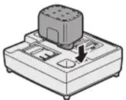
Attaching or Removing Socket
1. Attaching Socket
Attach the socket by sliding the female detent on the bottom of the socket to the square drive on the body.
Make sure the socket is firmly connected to the body.

natural_image
Diagram showing a cylindrical component being inserted into a plug socket (no text or symbols present)- Removing Socket Pull out the socket.
NOTE:
Attaching or Removing Original Options and Sockets
Keep the body above freezing point (0°C 32°F) when attach or detach
original options and sockets to the square drive on the body. The cushion rubber in the square drive to push up the ball may get hard under freezing point. This requires extra force in detaching and attaching sockets.
Attaching or Removing Battery Pack
- To connect the battery pack:
Line up the alignment marks and attach the battery pack.
- Slide the battery pack until it locks into position.

- To remove the battery pack:
Push on the button from the front to release the battery pack.

III. OPERATION
[Main Body]
Switch and Forward/Reverse Lever Operation

CAUTION:
To prevent damage, do not operate Forward/Reverse lever until the bit comes to a complete stop.
Forward Rotation Switch Operation
- Push the lever for forward rotation.
- Depress the trigger switch slightly to start the tool slowly.
- The speed increases with the amount of depression of the trigger for efficient tightening of screws. The brake operates and the bit stops immediately when the trigger is released.
- After use, set the lever to its center position (switch lock).
Reverse Rotation Switch Operation
- Push the lever for reverse rotation. Check the direction of rotation before use.
- Depress the trigger switch slightly to start the tool slowly.
- After use, set the lever to its center position (switch lock).
CAUTION:
• To eliminate excessive temperature increase of the tool surface, do not operate the tool continuously using two or more battery packs. Tool needs cool off time before switching to another pack.
How to Use the Belt Hook
WARNING!
- Be sure to attach the belt hook securely to the main unit with the screw firmly fastened. When the belt hook is not firmly attached to the main unit, the hook may disconnect and the main unit may fall. This may result in an accident or injury.
- Periodically check screw for tightness. If found to be loose, tighten firmly.
- Be sure to attach the belt hook firmly and securely onto a waist belt or other belt. Pay attention that the unit does not slip off the belt. This may result in an accident or injury
- When the main unit is held by the belt hook, avoid jumping or running with it. Doing so may cause the hook to slip and the main unit may fall.
This may result in an accident or injury.
- When the belt hook is not used, be sure to return it to the storing position. The belt hook may catch on something. This may result in an accident or injury.
- When the unit is hooked onto the waist belt by the belt hook, do not attach driver bits to the unit. A sharp edge object, such as a drill bit, may cause injury or an accident.
To Set the Belt Hook Angle Position
-
Slide the belt hook lock lever ① and hold it to unlock the belt hook.
-
Pull the belt hook from storing position ② and set it.
-
Release the belt hook lock lever to lock the angle of belt hook.
-
Make sure the belt hook is firmly locked. Also make sure the belt hook is firmly locked into position③.
• The belt hook cannot be locked in this position. Firmly lock it into position before use.


To return the belt hook to the storing position, Follow step 1. and 2. above, then lower the belt hook.
To secure the lock, follow 3 and 4 above.
To Change the Belt Hook Location Side
The belt hook can be attached to either side of the unit.

natural_image
Illustration of a medical device being adjusted for a lap joint (no text or symbols present)- Set the belt hook at storing position.
- Loosen the screw turning it counterclockwise, using a flat metal or a flat blade screw driver.
- Take out the belt hook and insert into the other side of the slot on the main unit.
- Fasten the screw firmly, turning it clockwise.
The belt hook can be taken out from the main unit only when it is at storing position.
Control Panel

(1) Impact Power Mode Select
- Selecting the impact power among 3 modes (Soft, Medium, Hard).
Press the impact power mode button to set it. The mode changes to hard, medium, or soft each time the button is pressed.
The driver is preset to "hard" impact mode setting when shipped from the manufacturer.
Recommended work guideline table
| Impact Power mode Display | Recommended Application |
H  0 – 2300 r.p.m. and0 – 3000 i.p.m. 0 – 2300 r.p.m. and0 – 3000 i.p.m. | Jobs requiring a high level of torque where there is no possibility of the bolts or screw breaking, its top shearing off, or the bit coming loose. (This setting provides maximum torque.) Suitable applications include:• Tightening M8 and larger bolts• Tightening long screws during interior finishing work |
M  0 – 1400 r.p.m. and0 – 2800 i.p.m. 0 – 1400 r.p.m. and0 – 2800 i.p.m. | Jobs requiring limited torque where there is a possibility of the screw breaking or its top shearing off. (This setting limits torque.) Suitable applications include:• Tightening bolts with smaller diameters (M6)• Tightening metalwork screws when installing fixtures |
S  0 – 1000 r.p.m. and0 – 2000 i.p.m. 0 – 1000 r.p.m. and0 – 2000 i.p.m. | Jobs requiring limited torque where there is a possibility of the screw breaking, its top shearing off, or the bit coming loose and damaging a finished exterior surface. (This setting limits torque.) Suitable applications include:• Tightening bolts smaller than M6 that may shear easily• Tightening screws into molded plastic• Installing gypsum wallboard |
* i.p.m. = Impact per minute.
(2) LED light

adversely affect the performance of the tool during use or its battery capacity.
CAUTION:
• The built-in LED light is designed to illuminate the small work area temporarily.
- Do not use it as a substitute for a regular flashlight, since it does not have enough brightness.
- LED light turns off when the tool has not been used for 5 minutes.
Caution : DO NOT STARE INTO BEAM.
Use of controls or adjustments or performance of procedures other than those specified herein may result in hazardous radiation exposure.
(3) Overheat warning lamp
Off (normal operation)


Flashing: Overheat Indicates operation has been halted due to motor or battery overheating.
The overheating protection feature halts driver operation to protect the motor and battery pack in the event of overheating. The overheat warning lamp on the control panel flashes when this feature is active.
- If the overheating protection feature activates, allow the driver to cool thoroughly (at least 30 minutes). The driver is ready for use when the overheat warning lamp goes out.
- Avoid using the driver in a way that causes the overheating protection feature to activate repeatedly.
(4) Battery low warning lamp


Off (normal operation)
Flashing (No charge) Battery protection feature active
Excessive (complete) discharging of Li-ion batteries shortens their service life dramatically. The driver includes a battery protection feature designed to prevent excessive discharging of the battery pack.
- The battery protection feature activates immediately before the battery loses its charge, causing the battery low warning lamp to flash.
- If you notice the battery low warning lamp flashing, charge the battery pack immediately.
[Battery Pack]
For Appropriate Use of Battery Pack
Li-ion Battery Pack (EY9L40/EY9L41)
- For optimum battery life, store the Li-ion battery pack following use without charging it.
- When charging the battery pack, confirm that the terminals on the battery charger are free of foreign substances such as dust and water etc. Clean the terminals before charging the battery pack if any foreign substances are found on the terminals.
The life of the battery pack terminals may be affected by foreign substances such as dust and water etc. during operation.
- When battery pack is not in use, keep it away from other metal objects like: paper clips, coins, keys, nails, screws, or other small metal objects that can make a connection from one terminal to another. Shorting the battery terminals together may cause sparks, burns or a fire.
- When operating the battery pack, make sure the work place is well ventilated.
- When the battery pack is removed from the main body of the tool, replace the battery pack cover immediately in order to prevent dust or dirt from contaminating the battery terminals and causing a short circuit.

Battery Pack Life
The rechargeable batteries have a limited life. If the operation time becomes extremely short after recharging, replace the battery pack with a new one.
Battery Recycling
ATTENTION:
For environmental protection and recycling of materials, be sure that it is disposed of at an officially assigned location, if there is one in your country.
[Battery Charger]
Charging
Cautions for the Li-ion Battery Pack
- If the temperature of the battery pack falls approximately below -10^ (14°F), charging will automatically stop to prevent degradation of the battery.
Common Cautions for the Li-ion/Ni-MH/Ni-Cd Battery Pack
- The ambient temperature range is between 0^ (32°F) and 40^ (104°F).
If the battery pack is used when the battery temperature is below 0^ C ( 32^ F), the tool may fail to function properly.
- When charging a cool battery pack (below 0^ (32^) ) in a warm place, leave the battery pack at the place and wait for more than one hour to warm up the battery to the level of the ambient temperature.
- Cool down the charger when charging more than two battery packs consecutively.
- Do not insert your fingers into contact hole, when holding charger or any other occasions.
CAUTION:
To prevent the risk of fire or damage to the battery charger.
- Do not use power source from an engine generator.
- Do not cover vent holes on the charger and the battery pack.
- Unplug the charger when not in use.
Li-ion Battery Pack
NOTE:
Your battery pack is not fully charged at the time of purchase. Be sure to charge the battery before use.
Battery charger (EY0L80)
- Plug the charger into the AC outlet.
NOTE:
Sparks may be produced when the plug is inserted into the AC power supply, but this is not a problem in terms of safety.
- Insert the battery pack firmly into the charger.
1 Line up the alignment marks and place the battery onto the dock on the charger.
2 Slide forward in the direction of the arrow.

- During charging, the charging lamp will be lit.
When charging is completed, an internal electronic switch will automatically be triggered to prevent overcharging.
-
Charging will not start if the battery pack is warm (for example, immediately after heavy-duty operation).
The orange standby lamp will be flashing until the battery cools down.
Charging will then begin automatically. -
The charge lamp (green) will flash slowly once the battery is approximately 80% charged.
- When charging is completed, the charging lamp will start flashing quickly in green color.
- If the temperature of the battery pack is 0^ C or less, charging takes longer to fully charge the battery pack than the standard charging time.
Even when the battery is fully charged, it will have approximately 50% of the power of a fully charged battery at normal operating temperature.
- If the power lamp does not light immediately after the charger is plugged in, or if after the standard charging time the charging lamp does not flash quickly in green, consult an authorized dealer.
- If a fully charged battery pack is inserted into the charger again, the charging lamp lights up. After several minutes, the charging lamp may flash quickly to indicate the charging is completed.
Ni-MH/Ni-Cd Battery Pack
NOTE:
When you charge the battery pack for the first time, or after prolonged storage, charge it for about 24 hours to bring the battery up to full capacity.
Battery charger (EY0L80)
- Plug the charger into the AC outlet.
NOTE:
Sparks may be produced when the plug is inserted into the AC power supply, but this is not a problem in terms of safety.
- Insert the battery pack firmly into the charger.
natural_image
Illustration of a mechanical device with a cylindrical component and a directional arrow (no text or symbols)- During charging, the charging lamp will be lit.
When charging is completed, an internal electronic switch will automatically be triggered to prevent overcharging.
-
Charging will not start if the battery pack is warm (for example, immediately after heavy-duty operation).
The orange standby lamp will be flashing until the battery cools down. Charging will then begin automatically. -
When charging is completed, the charging lamp will start flashing quickly in green color.
-
If the charging lamp does not light immediately after the charger is plugged in, or if after the standard charging time the charging lamp does not flash quickly in green, consult an authorized dealer.
- If a fully charged battery pack is inserted into the charger again, the charging lamp lights up. After several minutes, the charging lamp may flash quickly to indicate the charging is completed.
LAMP INDICATIONS


Green Lit
Charger is plugged into the AC outlet.
Ready to charge.
Green Flashing Quickly
Charging is completed. (Full charge.)
Green Flashing
Battery is approximately 80% charged (Usable charge. Li-ion only).
Green Lit
Now charging
Orange Lit
Battery pack is cool.
The battery pack is being charged slowly to reduce the load on the battery. (Li-ion only)
Orange Flashing
Battery pack is warm. Charging will begin when temperature of battery pack drops.
If the temperature of the battery pack is -10^ or less, the charging status lamp (orange) will also start flashing. Charging will begin when the temperature of the battery pack goes up (Li-ion only).
Charging Status Lamp
Left: green Right: orange will be displayed.
Both Orange and Green Flashing Quickly
Charging is not possible. Clogged with dust or malfunction of the battery pack.
Information for Users on Collection and Disposal of Old Equipment and used Batteries


Cd
These symbols on the products, packaging, and/or accompanying documents mean that used electrical and electronic products and batteries should not be mixed with general household waste.
For proper treatment, recovery and recycling of old products and used batteries, please take them to applicable collection points, in accordance with your national legislation and the Directives 2002/96/EC and 2006/66/EC.
By disposing of these products and batteries correctly, you will help to save valuable resources and prevent any potential negative effects on human health and the environment which could otherwise arise from inappropriate waste handling.
For more information about collection and recycling of old products and batteries, please contact your local municipality, your waste disposal service or the point of sale where you purchased the items.
Penalties may be applicable for incorrect disposal of this waste, in accordance with national legislation.
For business users in the European Union
If you wish to discard electrical and electronic equipment, please contact your dealer or supplier for further information.
[Information on Disposal in other Countries outside the European Union]
These symbols are only valid in the European Union. If you wish to discard these items, please contact your local authorities or dealer and ask for the correct method of disposal.
Note for the battery symbol (bottom two symbol examples):
This symbol might be used in combination with a chemical symbol. In this case it complies with the requirement set by the Directive for the chemical involved.
IV. MAINTENANCE
Use only a dry, soft cloth for wiping the unit. Do not use a damp cloth, thinner, benzine, or other volatile solvents for cleaning.
V. TIGHTENING TORQUE
The power required for tightening a bolt will vary, according to bolt material and size, as well as the material being bolted. Choose the length of tightening time accordingly.
Reference values are provided below.
(They may vary according to tightening conditions.)
Factors Affecting Tightening Torque
The tightening torque is affected by a wide variety of factors including the followings. After tightening, always check the torque with a torque wrench.
1) Voltage
When the battery pack becomes nearly discharged, the voltage decreases and the tightening torque drops.
Bolt Tightening Conditions

line
| Tightening time (Sec.) | M10 | M12 | M14 | M16 | | ---------------------- | ------- | ------- | ------- | ------- | | 0.00 | 0 | 0 | 0 | 0 | | 0.51 | ~49.0 | ~98.0 | ~147.0 | ~196.0 | | 1.02 | ~98.0 | ~196.0 | ~200.0 | ~200.0 | | 1.52 | ~147.0 | ~200.0 | ~200.0 | ~200.0 | | 2.02 | ~196.0 | ~200.0 | ~200.0 | ~200.0 | | 2.53 | ~200.0 | ~200.0 | ~200.0 | ~200.0 |
line
| Tightening time (Sec.) | M8 | M10 | M12 | | ---------------------- | ------ | ------ | ------ | | 0.00 | 0 | 0 | 0 | | 0.51 | ~200 | ~300 | ~400 | | 1.02 | ~400 | ~600 | ~900 | | 1.52 | ~600 | ~900 | ~1470 | | 2.02 | ~800 | ~1200 | ~1960 | | 2.53 | ~1000 | ~1500 | ~1960 |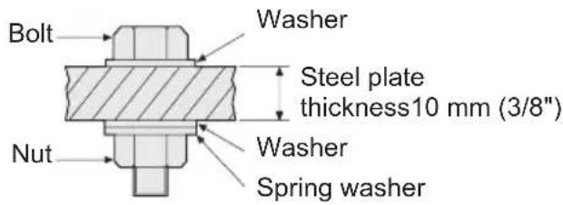
Tightening conditions
• The following bolts are used. Standard bolts: Strength type 4.8 High tensile type 12.9

2) Tightening time
Longer tightening time results in increased tightening torque. Excessive tightening, however, adds no value and reduces the life of the tool.
3) Different bolt diameters
The size of the bolt diameter affects the tightening torque.
Generally, as the bolt diameter increases, tightening torque rises.
4) Tightening conditions
- Tightening torque will vary, even with the same bolt, according to grade, length, and torque coefficient (the fixed coefficient indicated by the manufacturer upon production).
- Tightening torque will vary, even with the same bolting material (e.g. steel), according to the surface finish.
- Torque is greatly reduced when the bolt and nut start turning together.
5) Socket play
Torque is lowered as the six-sided configuration of the socket of the wrong size is used to tighten a bolt.
6) Switch (Variable speed control trigger)
Torque is lowered if the unit is used with the switch not fully depressed.
7) Effect of connecting adaptor
The tightening torque will be lowered through the use of a universal joint or a connecting adaptor.
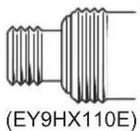
VI. ACCESSORIES
Use only bits suitable for size of drill's chuck.
Use Panasonic original Optional Quick change chuck (EY9HX110E) for maximum performance.
VII. APPENDIX
MAXIMUM RECOMMENDED CAPACITIES
| Model | EY7541 | |
| Bolt fastening | Standard bolt: M6 – M16High tensile bolt M6 – M12 | |
| Screw driving | Wood screw | 3.5 – 9.5 mm (1/8" – 3/8") |
| Self-drilling screw | 3.5 – 6 mm (1/8" – 1/4") | |
VIII. SPECIFICATIONS
MAIN UNIT
| Model EY7541 | ||
| Motor 14.4 V DC | ||
| No load speed | soft mode 0 – 1000 min | -1 (rpm) |
| medium mode 0 – 1400 min | -1 (rpm) | |
| hard mode 0 – 2300 min | -1 (rpm) | |
| Maximum torque 185 N·m (1890 kgf·cm, 1640 in-lbs) | ||
| Impact per minute | soft mode 0 – 2000 min | -1 (ipm) |
| medium mode 0 – 2800 min | -1 (ipm) | |
| hard mode 0 – 3000 min | -1 (ipm) | |
| Overall length 167 mm (6-9/16") | ||
| Weight (with battery pack: EY9L40) 1.5 kg (3.3 lbs) | ||
| Weight (with battery pack: EY9L41) 1.55 kg (3.4 lbs) | ||
| NoiseVibration | See the included sheet. | |
BATTERY PACK
| Model | EY9L40 | EY9L41 |
| Storage battery | Li-ion Battery | |
| Battery voltage | 14.4 V DC (3.6 V × 4 cells) | |
| Capacity | 3 Ah | 3,3 Ah |
BATTERY CHARGER
| Model | EY0L80 |
| Rating | See the rating plate on the bottom of the charger. |
| Weight | 0.95 kg (2.1 lbs) |
[Li-ion battery pack]
| Charging time | 3 Ah | 14.4 V | 21.6 V | 28.8 V |
| EY9L40 | EY9L60 | EY9L80 | ||
| Usable: 35 min. | Usable: 45 min. | Usable: 55 min. | ||
| Full: 50 min. | Full: 60 min. | Full: 70 min. |
| Charging time | 3,3 Ah | 14.4 V | ||
| EY9L41 | ||||
| Usable: 45 min. | ||||
| Full: 60 min. |
[Ni-Cd/Ni-MH battery pack]
| Charging time | 7.2 V | 9.6 V 12 | V 15.6 V 18 | V 24 V | |||
| 1.2 Ah | EY9065 | EY9080 | EY9001 | ||||
| EY9066 | EY9086 | ||||||
| 20 min. | |||||||
| 1.7 Ah | EY9180 | EY9101 | |||||
| EY9182 | EY9103 | ||||||
| 25 min. | |||||||
| 2 Ah | EY9168 EY9188 | EY9106 | EY9136 | EY9116 | |||
| EY9107 | EY9117 | ||||||
| EY9108 | |||||||
| 30 min. | 60 min. | ||||||
| 3 Ah | EY9200 EY9230 EY9210 | ||||||
| 45 min. 90 min. | |||||||
| 3.5 Ah | EY9201 EY9231 EY9251 | ||||||
| 55 min. 65 min. | |||||||
NOTE: This chart may include models that are not available in your area.
Please refer to the latest general catalogue
NOTE: For the dealer name and address, please see the included warranty card.
ONLY FOR U. K.
IX. ELECTRICAL PLUG INFORMATION
FOR YOUR SAFETY PLEASE READ THE FOLLOWING TEXT CAREFULLY
This appliance is supplied with a moulded three pin mains plug for your safety and convenience.
A 5 amp fuse is fitted in this plug.
Should the fuse need to be replaced please ensure that the replacement fuse has a rating of 5 amp and that it is approved by ASTA or BSI to BS1362.
Check for the ASTA mark or the BSI mark on the body of the fuse.
If the plug contains a removable fuse cover you must ensure that it is refitted when the fuse is replaced.
If you lose the fuse cover the plug must not be used until a replacement cover is obtained.
A replacement fuse cover can be purchased from your local Panasonic Dealer.
IF THE FITTED MOULDED PLUG IS UNSUITABLE FOR THE SOCKET OUTLET IN YOUR HOME THEN THE FUSE SHOULD BE REMOVED AND THE PLUG CUT OFF AND DISPOSED OF SAFELY.
THERE IS A DANGER OF SEVERE ELECTRICAL SHOCK IF THE CUT OFF PLUG IS INSERTED INTO ANY 13 AMP SOCKET.
If a new plug is to be fitted please observe the wiring code as shown below.
If in any doubt please consult a qualified electrician.
IMPORTANT:
The wires in this mains lead are coloured in accordance with the following code:
Blue: Neutral
Brown: Live
As the colours of the wire in the mains lead of this appliance may not correspond with the coloured markings identifying the terminals in your plug, proceed as follows.
The wire which is coloured BLUE must be connected to the terminal in the plug which is marked with the letter N or coloured BLACK.
The wire which is coloured BROWN must be connected to the terminal in the plug which is marked with the letter L or coloured RED.
Under no circumstances should either of these wires be connected to the earth terminal of the three pin plug, marked with the letter E or the Earth Symbol 12 .
How to replace the fuse: Open the fuse compartment with a screwdriver and replace the fuse and fuse cover if it is removable.

This apparatus was produced to BS800.
qualified
natural_image
Diagram showing a cylindrical object being inserted into a plug (no text or symbols present)natural_image
Illustration of a person's lower body and hip joint with a mechanical device (no text or symbols visible)natural_image
Line drawing of hands holding a handheld device (no text or symbols visible)natural_image
Illustration of a mechanical device with a cylindrical component and a downward arrow indicating motion (no text or symbols)natural_image
Diagram showing a mechanical component being inserted into a cylindrical housing (no text or symbols present)natural_image
Illustration of a person's seatbelt fastener and a mechanical device with a wrench (no text or symbols)natural_image
Line drawing of a hand holding a flashlight next to a portable device (no text or symbols)natural_image
Illustration of a mechanical device with a cylindrical component and a knob, no text or symbols presentnatural_image
Diagram showing a cylindrical component being inserted into a plug socket (no text or symbols present)natural_image
Illustration of a robotic device with a tool and a base device, no text or symbols presentnatural_image
Illustration of a person using a medical device to adjust a tool (no text or symbols present)natural_image
Illustration of a mechanical device with a cylindrical component and a knob, showing no text or symbols.natural_image
Diagram showing a mechanical component with two arrows indicating direction (no text or symbols)natural_image
Illustration of a robotic device with a sensor and directional arrow on a base (no text or symbols)natural_image
Illustration of a person's seatbelt buckle being adjusted for a cable or spring (no text or symbols present)Uit (normale werking


natural_image
Illustration of a mechanical component with a cylindrical top and base, showing a downward arrow indicating direction (no text or symbols present)natural_image
Diagram showing a cylindrical component being inserted into a plug (no text or symbols present)natural_image
Illustration of a mechanical device with a button and handle, no visible text or symbolsnatural_image
Diagram of a mechanical component with two arrows indicating direction (no text or symbols)natural_image
Technical illustration of a mechanical device with a spring-loaded handle and a separate view showing the same component (no text or symbols present)natural_image
Illustration of a mechanical device with a button and handle, no visible text or symbolsnatural_image
Diagram showing a cylindrical object being inserted into a mechanical component (no text or symbols present)natural_image
Illustration of a person's seatbelt fastener and a handheld device with a scroll wheel (no text or symbols)natural_image
Illustration of a mechanical device with a cylindrical component and a directional arrow (no text or symbols)natural_image
Diagram showing a cylindrical component being inserted into a plug (no text or symbols present)natural_image
Illustration of a person using a cable buckle device to interact with a tool (no text or symbols present)(3) Varsellampe for overoppheting

natural_image
Illustration of a mechanical device with a cylindrical component and a downward arrow indicating motion (no text or symbols)natural_image
Diagram showing a cylindrical component being inserted into a plug (no text or symbols present)natural_image
Illustration of a medical device with a clamp and connector, showing a close-up view of the device's handle (no text or symbols present)natural_image
Illustration of a mechanical device with a cylindrical component and a downward arrow indicating rotation (no text or symbols)VIII. TEKNISET TIEDOT
PÄÄLAITE
natural_image
Diagram of a mechanical component with arrows indicating direction (no text or symbols)natural_image
Mechanical tool with threaded end and spring mechanism (no text or symbols)natural_image
Illustration of hands using a handheld device to interact with a device (no text or symbols visible)natural_image
Illustration of a mechanical device with a cylindrical component and a downward arrow indicating a force or movement (no text or symbols present)natural_image
Diagram showing a cylindrical object being inserted into a plug socket (no text or symbols present)natural_image
Line drawing of a mechanical device with a threaded end and handle, showing no text or symbols.natural_image
Illustration of a mechanical device with a cylindrical component and a downward arrow indicating motion (no text or symbols)

- Read "the Safety Instructions" booklet and the following before using.
- ADDITIONAL SAFETY RULES
- WARNING:
- ASSEMBLY
- NOTE:
- Attaching or Removing Socket
- Attaching Socket
- Attaching or Removing Battery Pack
- OPERATION
- [Main Body]
- Switch and Forward/Reverse Lever Operation
- CAUTION:
- Forward Rotation Switch Operation
- Reverse Rotation Switch Operation
- How to Use the Belt Hook
- WARNING!
- To Set the Belt Hook Angle Position
- To Change the Belt Hook Location Side
- Control Panel
- Impact Power Mode Select
- LED light
- Overheat warning lamp
- Battery low warning lamp
- [Battery Pack]
- For Appropriate Use of Battery Pack
- Li-ion Battery Pack (EY9L40/EY9L41)
- Battery Pack Life
- Battery Recycling
- ATTENTION:
- [Battery Charger]
- Charging
- Cautions for the Li-ion Battery Pack
- Common Cautions for the Li-ion/Ni-MH/Ni-Cd Battery Pack
- Li-ion Battery Pack
- Battery charger (EY0L80)
- Ni-MH/Ni-Cd Battery Pack
- LAMP INDICATIONS
- Information for Users on Collection and Disposal of Old Equipment and used Batteries
- For business users in the European Union
- [Information on Disposal in other Countries outside the European Union]
- Note for the battery symbol (bottom two symbol examples):
- MAINTENANCE
- TIGHTENING TORQUE
- Factors Affecting Tightening Torque
- 1) Voltage
- Tightening conditions
- 2) Tightening time
- 3) Different bolt diameters
- 4) Tightening conditions
- 5) Socket play
- 6) Switch (Variable speed control trigger)
- 7) Effect of connecting adaptor
- ACCESSORIES
- APPENDIX
- SPECIFICATIONS
- ONLY FOR U. K.
- ELECTRICAL PLUG INFORMATION
- FOR YOUR SAFETY PLEASE READ THE FOLLOWING TEXT CAREFULLY
- IMPORTANT:
- TEKNISET TIEDOT
Brand : PANASONIC
Model : EY7541
Category : Screwdriver