
EY7881 - Cordless drill PANASONIC - Free user manual and instructions
Find the device manual for free EY7881 PANASONIC in PDF.
| Product Type | Cordless Electric Drill - Rotary Hammer |
| Brand | Panasonic |
| Model | EY7881 |
| Overall Length | 368 mm |
| Weight (with battery EY9L84) | 3.85 kg |
| Power Supply | Li-ion battery 28.8 V DC |
| Compatible Battery Models | EY9L82 (28.8 V), EY9L84 (28.8 V) |
| No-load Speed | Low mode: 0–560 min⁻¹, Medium mode: 0–680 min⁻¹, High mode: 0–840 min⁻¹ |
| Impact Frequency | Low mode: 0–2950 min⁻¹, Medium mode: 0–3600 min⁻¹, High mode: 0–4400 min⁻¹ |
| Max Drilling Diameter (concrete) | 28 mm |
| Max Drilling Diameter (steel) | 50 mm (hole cutting) |
| Max Drilling Diameter (wood) | 33 mm |
| Operating Modes | Rotation with impact, Rotation only, 3 adjustable speeds |
| Lighting | Built-in LED (temporary work area lighting) |
| Battery Level Indicator | 3 levels (full, 60%, low, empty flashing) |
| Battery Protection | Overheat, overcharge and over-discharge protection |
| Operating Temperature | 0 °C to 40 °C |
| Charging Temperature | 0 °C to 40 °C |
| Charger Model | EY0L82 (weight 0.93 kg) |
| Charging Time (full) | EY9L82: 80 min, EY9L84: 90 min |
| Included Accessories (depending on destination) | Drill chuck EY9HX402E, side handle, depth gauge |
| Optional Accessories | Dust collector EY9X004E, EY9X400E |
| Maintenance and Cleaning | Clean with a dry, clean cloth; do not use water or solvent |
| Warranty | Damage due to prolonged heavy use is not covered |
Frequently Asked Questions - EY7881 PANASONIC
User questions about EY7881 PANASONIC
0 question about this device. Answer the ones you know or ask your own.
Ask a new question about this device
Download the instructions for your Cordless drill in PDF format for free! Find your manual EY7881 - PANASONIC and take your electronic device back in hand. On this page are published all the documents necessary for the use of your device. EY7881 by PANASONIC.
USER MANUAL EY7881 PANASONIC
Cordless Rotary Hammer
Kabellos Bohrhammer
Before operating this unit, please read these instructions completely and save this manual for future use.
NOTE: Not all battery packs display the alignment mark (L).
Original instructions: English Translation of the original instructions: Other languages
WARNING
Read all safety warnings and all instructions. Failure to follow the warnings and instructions may result in electric shock, fire and/or serious injury.
Save all warnings and instructions for future reference.
I. INTENDED USE
This tool is a Rotary Hammer for drilling in concrete. In addition, the tool has a "rotation only mode" without hammering. The mode is suitable for metal-drilling, wood-drilling.
II. ADDITIONAL SAFETY RULES
Hammer safety warnings
- Wear ear protectors. Exposure to noise can cause hearing loss.
- Use auxiliary handle (support handle) supplied with the tool.
Loss of control can cause personal injury.
- Hold power tool by insulated gripping surfaces, when performing an operation where the cutting accessory may contact hidden wiring or its own cord. Cutting accessory contacting a "live" wire may make exposed metal parts of the power tool "live" and could give the operator an electric shock.
1) While working, use safety equipment such as protective glasses, and where necessary an anti-dust mask, anti-slip safety boots, helmet and ear protectors.
2) If the bit becomes jammed, immediately turn the trigger switch off to prevent an overload, which can damage the battery pack or motor. Use reverse motion to loosen jammed bits.
3) Do NOT operate Forward/Reverse lever when the trigger switch is on. The battery will discharge rapidly and damage to the main unit may occur.
4) During charging, the charger may become slightly warm. This is normal. Do NOT charge the battery for a long period.
5) Do not strain the tool by holding the speed control trigger halfway (speed control mode) so that the motor stops.
6) To prevent injury during use, hold the tool steady at all times and avoid waving it around.
7) Make certain that there are no hidden gas or water pipes, or electrical wires in the area where you will be working. Coming into contact with hidden pipes or wires could result in electric shock, or water or gas leaks.
8) Make sure to hold the object you are working on steady.
9) Check for damaged parts.
- Check thoroughly for damage to the protective cover and other parts before operating.
- Check to make sure the tool and all of its functions are working properly.
- Check the adjustment of all movable parts, and check all fixed parts to make sure they are fitted properly and free of damage. Check all parts of the tool for abnormal function.
10) When attempting to repair the protective cover or other parts, please follow the instructions in the user manual. In cases where there are no instructions in the manual, please take it back to the store to have it repaired.
11) If the tool gets exceptionally hot during use, please take it in for service and repair.
12) To avoid potential injury, keep face and hands away from the drill bit and any shavings.
13) Do not wear gloves when operating the tool, as they may get caught by the drill, leading to injury.
14) Battery terminals, screw shavings, and tool accessories such as drill bits will be very hot immediately after operation. Do not touch them as there is a risk of burning yourself.
| Symbol Meaning | |
| V | Volts |
| --- | Direct current |
| n0 | No load speed |
| ... min-1 | Revolutions or reciprocations per minutes |
| Ah | Electrical capacity of battery pack |
| Read the operating instructions before use. | |
| For indoor use only. | |
| T | Rotation with hammering |
| Rotation only | |
WARNING
- Do not use other than the Panasonic battery packs that are designed for use with this rechargeable tool.
- Panasonic is not responsible for any damage or accident caused by the use of recycled or counterfeit battery pack.
- Do not dispose of the battery pack in a fire, or expose it to excessive heat.
- Do not allow metal objects to touch the battery pack terminals.
- Do not carry or store the battery pack in the same container as nails or similar metal objects.
- Do not charge the battery pack in a high-temperature location, such as next to a fire or in direct sunlight. Otherwise, the battery may overheat, catch fire, or explode.
- After removing the battery pack from the tool or the charger, always reattach the pack cover. Otherwise, the battery contacts could be shorted, leading to a risk of fire.
WARNING
- When the Battery Pack Has Deteriorated, Replace It with a New One. Continued use of a damaged battery pack may result in heat generation, ignition or battery rupture.
-
To prevent leakage, overheating, smoke generation, fire, and rupturing from occurring, follow these instructions when handling our rechargeable power tools (tool main body/battery pack/charger).
-
Do not allow material cuttings or dust to fall onto the battery pack.
-
Before storing, remove any material cuttings and dust from the battery pack, fit red plastic "terminal cover", then place separately from metal objects (screws, nails, etc.) in tool case. Damage caused by loose objects in the case will not be covered by warranty.
-
Do not handle the rechargeable power tools in the following way.
(There is a hazard of smoke generation, fire, and rupturing)
- Use or leave in places exposed to rain or moisture
- Use submerging in water
III. ASSEMBLY
Attaching or Removing Bit
NOTE:
When attaching or removing a bit, disconnect battery pack from the main unit or place the switch in the center position (switch lock).
1. Attachment
NOTE:
Precautions for attaching the drill
- When using an old drill bit, for example, attachment may not be possible if its mounting section is deformed.
- Clean the mounting section of the drill bit and apply grease to it.
(1) Insert a bit into the mounting hole, and turn it slightly to locate an engaged position. [Fig.1]
(2) At the engaged position, push the bit as far as it goes. Make sure that the bit is fixed by pulling it.
2. Removal
- Depress the chuck cover and pull the bit. [Fig.2]
Attaching or Removing Battery Pack
Battery pack fixing
The battery pack is designed to be installed by proceeding two steps for safety. Make sure the battery pack is installed properly to the main body before use.
1. Attachment
(1) Flip the main unit upside down.
(2) To attach the battery pack:

Align the highlighted marker points and attach battery pack.
Slide the battery pack until it locks into position.
(3) Insert the battery pack until the battery pack fixing lever catches on the hook portion of the pack.

NOTE:
The overheat warning lamp (H) and the battery level indicator [E] (J) will flash when the battery pack is not inserted firmly.
2. Removal
(1) Flip the main unit upside down.
(2) To remove the battery pack: [Fig.5] While holding down the the battery fixing lever,do the following. (1) Push the button (2) and slide the battery pack backward.
IV. OPERATION

WARNING!
- Do not inhale smoke emitted from the main unit or battery pack as it may be harmful.
[Main Unit]
CAUTION
When storing or carrying the tool, set the Forward/Reverse lever to the center position (switch lock).
NOTE:
Exercise caution to ensure no objects come into contact with the tool's trigger switch.
If an object comes into contact with the tool's trigger switch, even while the Forward/Reverse lever is in the center position (locked), a small amount of electric current may continue flowing, which may cause an excessive discharge from the battery pack and subsequent battery pack failure.
Switch and Forward/Reverse Lever Operation [Fig.6]
- Push the lever for forward or reverse rotation. Check the direction of the lever before using.
-
Depress the trigger switch slightly to start the tool slowly.
-
Speed will increase by pressing the trigger. The tool stops working immediately by releasing the trigger.
- When done with an application, lock the switch by centering the lever.
NOTE:
When the brake operates, a braking sound may be heard. This is normal.
CAUTION:
When operating the tool by pulling the trigger, there may be a momentary lag before rotation starts. This does not signal a malfunction.
- This lag occurs as the tool's circuitry starts up when the trigger is pulled for the first time after installing a battery pack or after the tool has not been used for at least 1 minute (or at least 5 minutes when the LED is on). Rotation will start without any lag during second and subsequent operations.
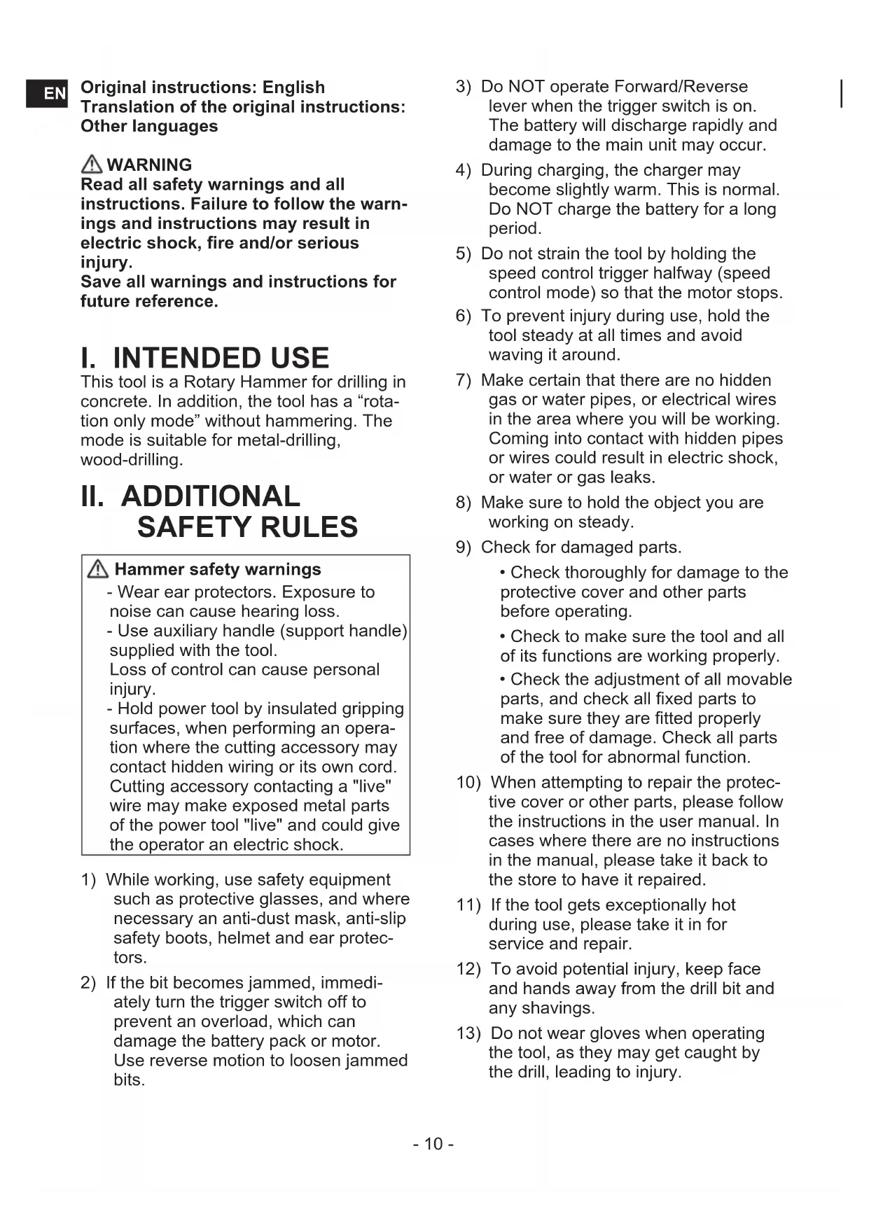
Hammering/drilling switching lever (C) / Speed setting button (K)
- There are six modes available with the combination of Hammering/drilling switching lever and Speed setting button.
Select the suitable mode for application.
- Operate the mode change after the motor rotation is completely stopped.
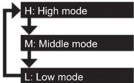
| Position of switching lever | Speed setting indicator | Recommended application |
| (Rotation with hammering) | This mode has hard blow hammering which is suitable for concrete drilling. •Concrete drill | |
| This mode is suitable for concrete drilling with smaller diameter drill, or for drilling into soft base material. •Small diameter concrete drill | ||
| By saving speed and blow force, it is suitable for drilling with a thin drill that is prone to breakege, or drilling on a brittle base metal. •Smaller diameter concrete drill | ||
| (Rotation only) | This mode is suitable for metal drilling with high speed rotation. •Metal drill •Metal hole saw •Stainless steel drill |
3 speed modes setting
Press the speed setting button (K). The mode changes each time the button is pressed.
EN
Variable speed control trigger
To set the center of a hole, pull the trigger slightly to start the drill rotation slowly.
Support handle [Fig.7]
Place the support handle at your favorite position and tighten the handle securely.
![PANASONIC EY7881 - Support handle [Fig.7] - 1](/content/2026/03/454751/images/02405aa31631c62f9acdea9b12c20d7f6716abbf6fdec215cf639ae129cbb38a.jpg)
CAUTION:
Always make sure to tighten the handle securely before use as illustrated below, to avoid injurt.
Depth gauge [Fig.8]
Loosen the support handle and adjust the depth gauge at your favorite depth.
After adjusting, tighten the support handle and fix depth gauge.
Control panel
(G) LED light [Fig.9]
Before the use of LED light, always pull the power switch once.
Press the LED light on button.
The light illuminates with very low current, and it does not adversely affect the performance of the tool during use or its battery capacity.
![PANASONIC EY7881 - LED light [Fig.9] - 1](/content/2026/03/454751/images/9b9ac47c891f7745efcf8b94e2b940ed7108d4706a17433473218ad221de2d11.jpg)
CAUTION:
- The built-in LED light is designed to illuminate the small work area temporarily.
- Do not use it as a substitute for a regular flashlight, since it does not have enough brightness.
CAUTION:DO NOT STARE INTO BEAM.
Use of controls or adjustments or performance of procedures other than those specified herein may result in hazardous radiation exposure.
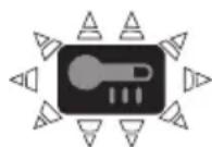
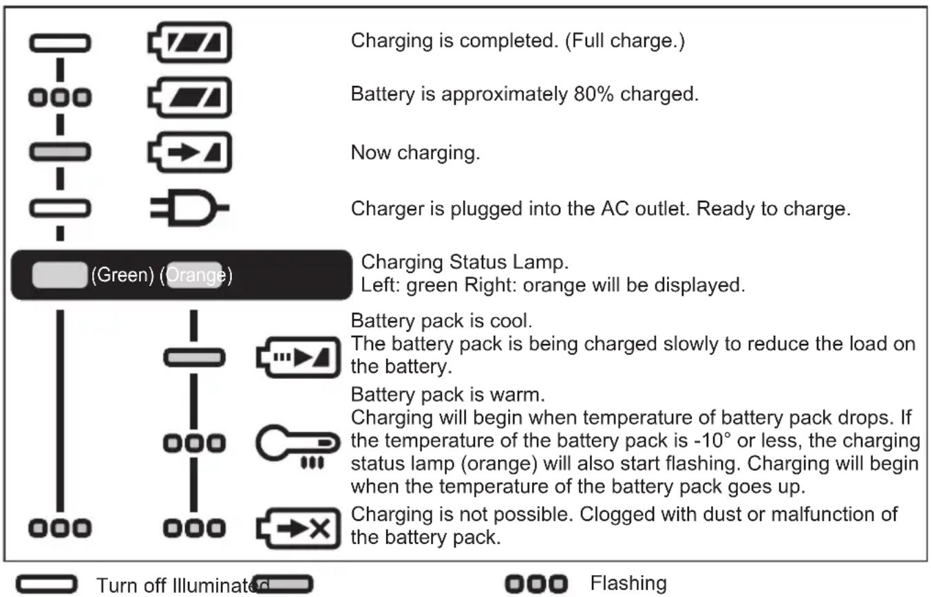
(I) Battery Level Indicator
Press the battery level button.
Battery level indicator shows battery level in three levels while pressing the button.
NOTE:
The indicator will not show the battery level when the button is pressed in the following cases.
The tool is powered off.
- Just after attaching the battery pack
- The main unit or battery level button is not operated for approx. five minutes. Press the battery level button again after depressing the trigger switch.
- If the battery temperature is high, stop the operation and wait until the battery temperature is low.
| Indicator Battery status | ||
| 3 lamps illuminated | Fully charged or high charge level | |
| 2 lamps illuminated | Approx. 60% remaining | |
| One lamp illuminated | Low level - Will require charging soon | |
| 3 lamps flashing | Empty - Immediate charging required | |
This battery level function is only a guide and indication may change due to the condition of the battery or ambient temperature.
Excessive (complete) discharging of lithium ion batteries shortens their service life dramatically. The driver includes a battery protection feature designed to prevent excessive discharging of the battery pack.
Warning Functions
(1) Overheat Warning


Off (normal operation)
Illuminated: Overheat (motor)
Flashing: Overheat (battery)
Indicates operation has been halted due to motor or battery overheating.
To protect the motor or battery, be sure to note the following when carrying out this operation.
- If the motor or battery becomes hot, the protection function will be activated and the motor or battery will stop operating. The overheat warning lamp on the control panel illuminates or flashes when this feature is active.
- If the overheating protection feature activates, allow the tool to cool thoroughly (at least 30 minutes). The tool is ready for use when the overheat warning lamp goes out.
- Avoid using the tool in a way that causes the overheating protection feature to activate repeatedly.
- If the tool is operated continuously under high-load conditions or if it is used in hot-temperature conditions (such as during summer), the overheating protection feature may activate frequently.
- If the tool is used in cold-temperature conditions (such as during winter) or if it is frequently stopped during use, the overheating protection feature may not activate.
(2) Voltage Reduction Warning
3 lamps flashing
If the tool is subject to a sudden load during use that causes the motor to lock up, the overdischarge prevention sensor may be triggered, and the battery low warning lamp may flash. The lamp will stop flashing once you address the cause of the motor's locking up and cycle the trigger.
(3) Overload Warning
If the tool is subject to a sudden load during use that causes the motor to lock up, the overcurrent prevention sensor may be triggered, the voltage reduction warning lamp may illuminate and flash. (Bottom of it illuminates and middle and top flashes.)
The lamp will stop illuminating and flashing once you address the cause of the motor's locking up and cycle the trigger.
[Battery Pack]
For Appropriate Use of Battery Pack [Fig.9]
- The rechargeable batteries have a limited life.
- Do not use the battery pack soaked in conductors like water.
- For optimum battery life, store the Li-ion battery pack following use without charging it.
- When operating the battery pack, make sure the work place is well ventilated.
For safe use
- The battery pack is designed to be installed by proceeding two steps for safety. Make sure the battery pack is installed properly to the main unit before use.
- If the battery pack is not connected firmly when the switch is switched on, the overheat warning lamp and the battery low warning lamp will flash to indicate that safe operation is not possible, and the main unit will not rotate normally. Connect the battery pack into the unit of the tool until the red or yellow label disappears.
- Only use rechargeable battery packs for Panasonic rechargeable tools. Do not use modified battery packs (including battery packs which have been disassembled and parts replaced).
- Do not use deteriorated battery packs. There is a risk of the generation of heat, ignition and explosion.
-
If a battery pack leaks fluid, cease use, keep away from open flames, and return it to the store immediately.
-
Attach the battery pack by sliding until the yellow and red labels are no longer visible, and check that it does not fall out of place.
- Failure to do so may result in scalding.
- The usage temperature range for lithium ion battery packs is 0 to 40 degrees.
- Use of battery packs cooled to below zero, such as in colder northern areas, may result in abnormal operation of the device. In such cases, leave the battery pack in a location of 10 degrees or more for one hour or more before use, and only use the device after the battery pack has warmed up.
[Battery Charger]
Charging
CAUTION:
1) If the temperature of the battery pack falls approximately below -10^ (14^) , charging will automatically stop to prevent degradation of the battery.
2) The ambient temperature range is between 0^ (32^) and 40^ (104^) . If the battery pack is used when the battery temperature is below 0^ (32^) , the tool may fail to function properly.
3) Use the charger at temperatures between 0^ and 40^ , and charge the battery at a temperature similar to that of the battery itself. (There should be no more than a 15^ difference between the temperatures of the battery and the charging location.)
4) When charging a cool battery pack (below 0^ (32^) ) in a warm place, leave the battery pack at the place and wait for more than one hour to warm up the battery to the level of the ambient temperature.
5) Cool down the charger when charging more than two battery packs consecutively.
6) Do not insert your fingers into contact hole, when holding charger or any other occasions.
7) Unplug the charger when not in use.
8) Store the charger between 0 and 40 degrees, and charge the battery pack at a temperature close to the storage temperature.
- If the battery pack is charged while at a temperature below 0 degrees, a full charge will give only around 50% of a normal charge. Commence charging after 1 hour or more at the prescribed temperature.
9) Do not charge in a poorly ventilated place.
10) Do not cover the battery pack or charger with a cloth or the like while charging is in progress.
NOTE:
Your battery pack is not fully charged at the time of purchase. Be sure to charge the battery before use.
How to charge
- Plug the charger into the AC outlet.
NOTE:
Sparks may be produced when the plug is inserted into the AC power supply, but this is not a problem in terms of safety.
- Connect the battery pack firmly into the charger.
(1) Line up the alignment marks and place the battery onto the dock on the charger.
NOTE:
Not all battery packs display the alignment mark (Q) (on page 2).
(2) Slide forward in the direction of the arrow. [Fig.10]
-
During charging, the charging lamp will be lit. When charging is completed, an internal electronic switch will automatically be triggered to prevent overcharging.
-
Charging will not start if the battery pack is hot (for example, immediately after heavy-duty operation).
The orange standby lamp will be flashing until the battery cools down. Charging will then begin automatically.
- The charge lamp (green) will flash slowly once the battery is approximately 80% charged.
- When charging is completed, the charging lamp in green color will turn off.
- If the temperature of the battery pack is 0^ or less, charging takes longer to fully charge the battery pack than the standard charging time. Even when the battery is fully charged, it will have approximately 50% of the power of a fully charged battery at normal operating temperature.
- Consult an authorized dealer if the charging lamp (green) does not turn off.
- If a fully charged battery pack is inserted into the charger again, the charging lamp lights up. After several minutes, the charging lamp in green color will turn off.
- Remove the battery pack while the battery pack release button is held up. [Fig.10]
LAMP INDICATIONS
ATTENTION:
For environmental protection and recycling of materials, be sure that it is disposed of at an officially assigned location, if there is one in your country.
Information for Users on Collection and Disposal of Old Equipment and used Batteries

These symbols on the products, packaging, and/or accompanying documents mean that used electrical and electronic products and batteries should not be mixed with general household waste.
For proper treatment, recovery and recycling of old products and used batteries, please take them to applicable collection points, in accordance with your national legislation and the Directives 2012/19/EC and 2006/66/EC.
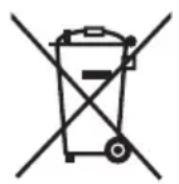
By disposing of these products and batteries correctly, you will help to save valuable resources and prevent any potential negative effects on human health and the environment which could otherwise arise from inappropriate waste handling.
For more information about collection and recycling of old products and batteries, please contact your local municipality, your waste disposal service or the point of sale where you purchased the items.
Penalties may be applicable for incorrect disposal of this waste, in accordance with national legislation.
[For business users in the European Union]
If you wish to discard electrical and electronic equipment, please contact your dealer or supplier for further information.
[Information on Disposal in other Countries outside the European Union]
These symbols are only valid in the European Union. If you wish to discard these items, please contact your local authorities or dealer and ask for the correct method of disposal.
Chisel Attachment (EY9HX402E) (will be included with shipment according to the destination)

CAUTION:
- The Chisel attachment is intended to be used with Rotary hammer EY7880/ EY7881. When used on another tool, it may create a risk of injury.
- Disconnect Battery pack from tool or place the switch in the locked off position before attach or remove the Chisel attachment. Such preventive safety measures reduce the risk of starting the tool accidentally.
-
Apply the lubricant grease on the shaft in the Chisel attachment before use.
-
The Chisel attachment creates heat. It may become very hot and may cause skin burns. Do not operate the Chisel attachment more than 30 minutes continuously.
To reduce the risk of injury, use the Support handle on the Rotary hammer. - Replace the Chisel attachment immediately when the Dust protect rubber cap is broken to avoid the dust coming inside the attachment.
Usage:
-
Use with a Chisel bit with SDS-Plus type shank in Rotation+Hammer mode, for Light duty chiseling (ceramic tile remove, scraping sealing material etc.)
-
To attach the Chisel attachment Remove the Support handle from the Rotary hammer. Mount the Chisel attachment on the tool. Make sure to eliminate a play between the attachment and tool. Fix the attachment firmly on the tool using the butterfly screw.
- Attach the Support handle on the Chisel attachment.
- Insert/detach the Chisel bit Read instruction manual of the Rotary hammer.
- To adjust the blade angle of the Chisel bit Rotate the Chisel attachment to adjust the blade angle of Chisel bit for better setting.
Dust Collection Cup (EY9X004E) (Available as an optional accessory)
- Drill bits of which diameter is 20mm above cannot be inserted through dust collection cup.
-
Do not use the tool for cutting other than concrete, mortar and other ceramic materials. If used for cutting metal materials, the dust collection cup may be damaged by the metal chip heat.
-
Install a drill bit.
- Pass the drill bit through A and fix the cup at B by matching with the shape of the support handle.
[Fig.11]
Operation [Fig.12]
Keep the dust collection cup in close contact with the wall surface during operation.
Removal [Fig.13]
Hold the base of the dust collection cup for removal.
Please remove after thoroughly getting rid of the dust in the dust collection cup.
Storage [Fig.14]
Do not store the dust collection cup in a compressed position. If kept in a compressed position, it may be impossible to return to the original shape.
V. MAINTENANCE
- Use only a dry, soft cloth for wiping the unit.
Do not use a damp cloth, thinner, benzine, or other volatile solvents for cleaning. - In the event that the inside of the tool or battery pack is exposed to water, drain and allow to dry as soon as possible.
Carefully remove any dust or iron filings that collect inside the tool. If you experience any problems operating the tool, consult with a repair shop.
VI. OPTIONAL ACCESSORIES
CAUTION:
To prevent the risk of injury, only use accessory or attachment for its stated purpose.
NOTE:
If you need any assistance for more details regarding these accessories, ask your local service center.
Chisel Attachment
- EY9HX402E
Dust Collection Cup
- EY9X004E
Dust Collection System
- EY9X400E
See the operating instruction "EY9X400".
VII. USAGE SUGGESTION
- If there isn't enough force pushing down on the bit, the hammer may not be able to blow in hammering mode. This is to prevent the hammering mode from operating with no load. Press down harder on the bit to engage the hammer and cause it to blow. Always be sure to press down with enough force when working.
- In winter or in other situations where the temperature of the unit is low (5^ or below), the blow of the hammering mode may be weaker than normal at the beginning stage. This is because the grease becomes stiffer in low temperatures, increasing friction. If this should happen, operating hammering mode with no load for approximately 30 seconds and repeat this 3 times. This will restore its blowing power.
VIII. SPECIFICATIONS
NOTE: Weight indication
Greater than or equal to 1kg : indicated by 0.05kg
Less than 1kg : indicated by 0.01kg
MAIN UNIT
| Maximum Drilling Diameter | Concrete | φ28 mm |
| Steel | φ50 mm (Metal hole saw) | |
| Wood | φ33 mm | |
| Motor Voltage 28.8 V DC | ||
| Speed At No Load (RPM) | Low Mode 0 – 560 min -1 (rpm) | |
| Middle Mode 0 – 680 min -1 (rpm) | ||
| High Mode 0 – 840 min -1 (rpm) | ||
| Blows Rate Per Minute (BPM) | Low Mode 0 – 2950 min -1 (bpm) | |
| Middle Mode 0 – 3600 min -1 (bpm) | ||
| High Mode 0 – 4400 min -1 (bpm) | ||
| Weight (with battery pack: EY9L84) | 3.85 kg | |
| Overall length 368 mm | ||
| Noise, Vibration See the included sheet | ||
BATTERY PACK
| Model No. EY9L82 EY9L84 | |||
| Storage battery Li-ion Battery | |||
| Battery | voltage DC 28.8 V | ||
| detail spec. 3.6 V × 16 cells 3.6 V × 8 cells | |||
BATTERY CHARGER
| Model | EY0L82 | |
| Electrical rating | See the rating plate on the bottom of the charger. | |
| Weight | 0.93 kg | |
| Charging time | EY9L82 EY9L84 | |
| Usable: 60 min | Usable: 60 min | |
| Full: 80 min | Full: 90 min | |
NOTE: This chart may include models that are not available in your area.
Please refer to the latest general catalogue.
IX. APPENDIX
WARRANTY SUPPLEMENT
- The breakdown and damage caused by usage consistent for a long time (e.g.: factory work on the assembly line, etc.) is out of warranty.
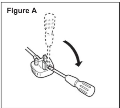
X. CAUTION FOR AC MAINS LEAD
FOR YOUR SAFETY PLEASE READ THE FOLLOWING TEXT CAREFULLY
This appliance is supplied with a moulded three pin mains plug for your safety and convenience. A 5 amp fuse is fitted in this plug.
Should the fuse need to be replaced please ensure that the replacement fuse has a rating of 5 amp and that it is approved by ASTA or BSI to BS1362.
Check for the ASTA mark or the BSI mark on the body of the fuse.
If the plug contains a removable fuse cover you must ensure that it is refitted when the fuse is replaced.
If you lose the fuse cover the plug must not be used until a replacement cover is obtained.
A replacement fuse cover can be purchased from your local Panasonic Dealer.
CAUTION:
IF THE FITTED MOULDED PLUG IS UNSUITABLE FOR THE SOCKET OUTLET IN YOUR HOME THEN THE FUSE SHOULD BE REMOVED AND THE PLUG CUT OFF AND DISPOSED OF SAFELY. THERE IS A DANGER OF SEVERE ELECTRICAL SHOCK IF THE CUT OFF PLUG IS INSERTED INTO ANY 13 AMP SOCKET.
How to replace the fuse
The location of the fuse differs according to the type of AC mains plug (figures A and B).
Confirm the AC mains plug fitted and follow the instructions below. Illustrations may differ from actual AC mains plug. Open the fuse cover with a screwdriver and replace the fuse and close or attach the fuse cover.

Manche de support [Fig.7]
Clignotant: Surchauffe (battery)
(G) Luce LED [Fig.9]
(G) LED-lampje [Fig.9]
(I) Indicator accuniveau
(G) LED-ljus [Fig.9]
Lyser: Overhettning (motor)
Blinkande: Overhett- ning (battery)
Sikkerhetsadvarsler for hammer
- Bruk hørselvern. Stoyeksponering kan fore til tap av hørsel.
- Bruk hjelpehandtaket (stottehandtak) som folger med verktoyet.
Tap av kontroll kan.fore til personskade.
- Hold elektriske verktøy på isolerte gripeeverflater nár du utfører en jobb der verktoyets kuttefunksjon kankommen i kontaktmed skjulte ledninger eller verktoyetsledning.
Kuttetilbehör somkommen i kontakt med en strømførende ledning kan lede strøm til eksponerte metalldeler på det elektriske verktøyet, og kan gi operatoren elektrisk støt.
(G) LED-valo [Fig.9]
VIII. TEKNISET TIEDOT
Importer for Turkey:
Panasonic Eco Solutions Elektnik San Tic A.S
Abdurrahmangazi Mah. Ebubekir Cad. No: 44
34887 Sancaktepe Istanbul/Turkiye
(G) Latarka LED [Fig.9]
(G) LED feny [Fig.9]
Vilagit: Tulmelegedes (motor)
Villog: Tulmelegedés (akkumulator)
Panasonic Testing Centre
Panasonic Europe Ltd. Hamburg office
Winsberging 15,
22525 Hamburg,
Germany
Panasonic Corporation
1006,Kadoma,Osaka 571-8501,Japan
http://www.panasonic.com
- Original instructions: English Translation of the original instructions: Other languages
- WARNING
- INTENDED USE
- ADDITIONAL SAFETY RULES
- Hammer safety warnings
- ASSEMBLY
- Attaching or Removing Bit
- NOTE:
- Attachment
- Removal
- Attaching or Removing Battery Pack
- Battery pack fixing
- OPERATION
- WARNING!
- [Main Unit]
- CAUTION
- Switch and Forward/Reverse Lever Operation [Fig.6]
- CAUTION:
- Hammering/drilling switching lever (C) / Speed setting button (K)
- speed modes setting
- EN
- Variable speed control trigger
- Support handle [Fig.7]
- Depth gauge [Fig.8]
- Control panel
- LED light [Fig.9]
- CAUTION:DO NOT STARE INTO BEAM.
- Battery Level Indicator
- Warning Functions
- Overheat Warning
- Voltage Reduction Warning
- lamps flashing
- Overload Warning
- [Battery Pack]
- For Appropriate Use of Battery Pack [Fig.9]
- For safe use
- [Battery Charger]
- Charging
- How to charge
- LAMP INDICATIONS
- ATTENTION:
- Information for Users on Collection and Disposal of Old Equipment and used Batteries
- [For business users in the European Union]
- [Information on Disposal in other Countries outside the European Union]
- Chisel Attachment (EY9HX402E) (will be included with shipment according to the destination)
- Usage:
- Dust Collection Cup (EY9X004E) (Available as an optional accessory)
- Operation [Fig.12]
- Removal [Fig.13]
- Storage [Fig.14]
- MAINTENANCE
- OPTIONAL ACCESSORIES
- Chisel Attachment
- Dust Collection Cup
- Dust Collection System
- USAGE SUGGESTION
- SPECIFICATIONS
- APPENDIX
- WARRANTY SUPPLEMENT
- CAUTION FOR AC MAINS LEAD
- FOR YOUR SAFETY PLEASE READ THE FOLLOWING TEXT CAREFULLY
- How to replace the fuse
- Manche de support [Fig.7]
- Luce LED [Fig.9]
- LED-lampje [Fig.9]
- Indicator accuniveau
- LED-ljus [Fig.9]
- Sikkerhetsadvarsler for hammer
- LED-valo [Fig.9]
- TEKNISET TIEDOT
- Latarka LED [Fig.9]
- LED feny [Fig.9]
Brand : PANASONIC
Model : EY7881
Category : Cordless drill