
TYWK42PR20 - TV PANASONIC - Free user manual and instructions
Find the device manual for free TYWK42PR20 PANASONIC in PDF.
| Product Type | Plasma TV |
| Screen Size | 42 inches (107 cm) |
| Resolution | 1920 x 1080 pixels (Full HD) |
| Weight (without stand) | Approx. 22 kg |
| Dimensions (without stand) | 1020 x 660 x 90 mm |
| Power Supply | 220-240 V ~ 50/60 Hz |
| Power Consumption | Approx. 250 W |
| Connectivity | 2 x HDMI, 1 x SCART, 1 x USB, 1 x PC input |
| Wall Mount Angle | Adjustable from 0° to 20° in 5° increments |
| Wall Mount Weight | Approx. 3.2 kg |
| Panel Material | Glass |
| Maintenance | Clean with a soft, dry cloth; for stubborn stains, use a diluted neutral detergent |
| Safety | Professional installation recommended; do not expose to moisture or excessive heat |
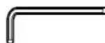
| Supplied Parts | Mounting brackets, M5x10 screws, M8x32 screws, washers, hex key |
| Compatibility | Only for specified Panasonic plasma screen |
| Operating Ambient Temperature | Do not exceed 40°C |
| Warranty | Refer to the manual for warranty conditions |
Frequently Asked Questions - TYWK42PR20 PANASONIC
User questions about TYWK42PR20 PANASONIC
0 question about this device. Answer the ones you know or ask your own.
Ask a new question about this device
Download the instructions for your TV in PDF format for free! Find your manual TYWK42PR20 - PANASONIC and take your electronic device back in hand. On this page are published all the documents necessary for the use of your device. TYWK42PR20 by PANASONIC.
USER MANUAL TYWK42PR20 PANASONIC
Fitting work and connection equipment expansion and removal should never be done by any other than a qualified installation specialist.
- Incorrect fitting may cause equipment to fall, resulting in injury.
Do not fit at a location that cannot bear the load.
- If the fitting location lacks sufficient strength the equipment may fall.
Include a safety factor when considering the strength of the proposed fitting location.
- If strength is not sufficient the equipment may fall, resulting in injury.
Do not disassemble or modify the wall-hanging bracket.
- Otherwise the unit may be dropped and become damaged, and personal injury may result.
Ensure that the installation location is strong enough to support long-term use.
- If its strength becomes insufficient over the course of long-term use, the plasma display may drop, possibly causing injury.
CAUTION
Do not use any plasma displays other than those given in the catalogue.
- Otherwise the unit may be dropped and become damaged, and personal injury may result.
Do not install the plasma display in any other way than the steps specified in these instructions.
- Otherwise the unit may be dropped and become damaged, and personal injury may result.
Do not fit facing upwards, sideways or upside down.
- This may cause heat to build up inside the plasma display, resulting in a fire.
Do not fit at any locations subject to humidity, dust, smoke, steam or heat.
- This may have an adverse effect on the plasma display and cause fire or electric shock.
Do not block the ventilation holes. When using the wall-hanging bracket, do not block the space between the rear surface of the plasma display and the wall surface.
- Otherwise heat may build up inside and cause a fire.
Secure at least 10 cm (3.9 inches) of space at the top, bottom, left, and right of the plasma display. Also
secure some space at the back.
- Failing to do so may result in a fire.
The work of fitting or removing the plasma display must be performed by at least two people.
- The plasma display may fall and cause injury.
For installation, use the special-purpose constituent parts.
- Otherwise, the plasma display may fall off the wall and/or be damaged, possibly causing injury.
Install the mounting screws and power cable in such a way that they will not make contact with the inside parts of the wall.
- Electric shocks may result from contact with any metal objects inside the wall.
When removing the plasma display, remove the wall-hanging brackets as well.
- Otherwise, bumping into the brackets, etc., may result in injury.
Requests regarding handling
1) Exercise care when selecting the location for the plasma display because it may discolor or deform due to light or heat if it is placed where it is exposed to direct sunlight, or near a heater.
2) Clean the wall-hanging bracket by wiping it with a soft, dry cloth (such as cotton or flannel). If the bracket is very dirty, remove the dirt using a neutral detergent diluted in water, and then wipe it clean with a dry cloth.
Do not use benzene, thinner, or furniture wax as this may cause the coating to peel.
(For information on cleaning the plasma display, see the plasma display's instruction manual. If using a chemically-treated cloth, follow the instructions supplied with the cloth.)
3) Do not affix adhesive tape or stickers to the product. Doing so may dirty the surface of the wall-hanging bracket. Do not allow long-term contact with rubber, vinyl products or the like. (Doing so will cause deterioration.)
4) The panel of the plasma display is glass. Do not subject it to a strong force or impact.
Caution:
This bracket is intended for only Panasonic plasma display models (See page 71).
Use with other apparatus is capable of resulting in instability causing possible injury.
PROFESSIONAL INSTALLATION IS REQUIRED.
PANASONIC DISCLAIMS ANY PROPERTY DAMAGE AND/OR SERIOUS INJURY, INCLUDING DEATH
RESULTING FROM IMPROPER INSTALLATION OR INCORRECT HANDLING.
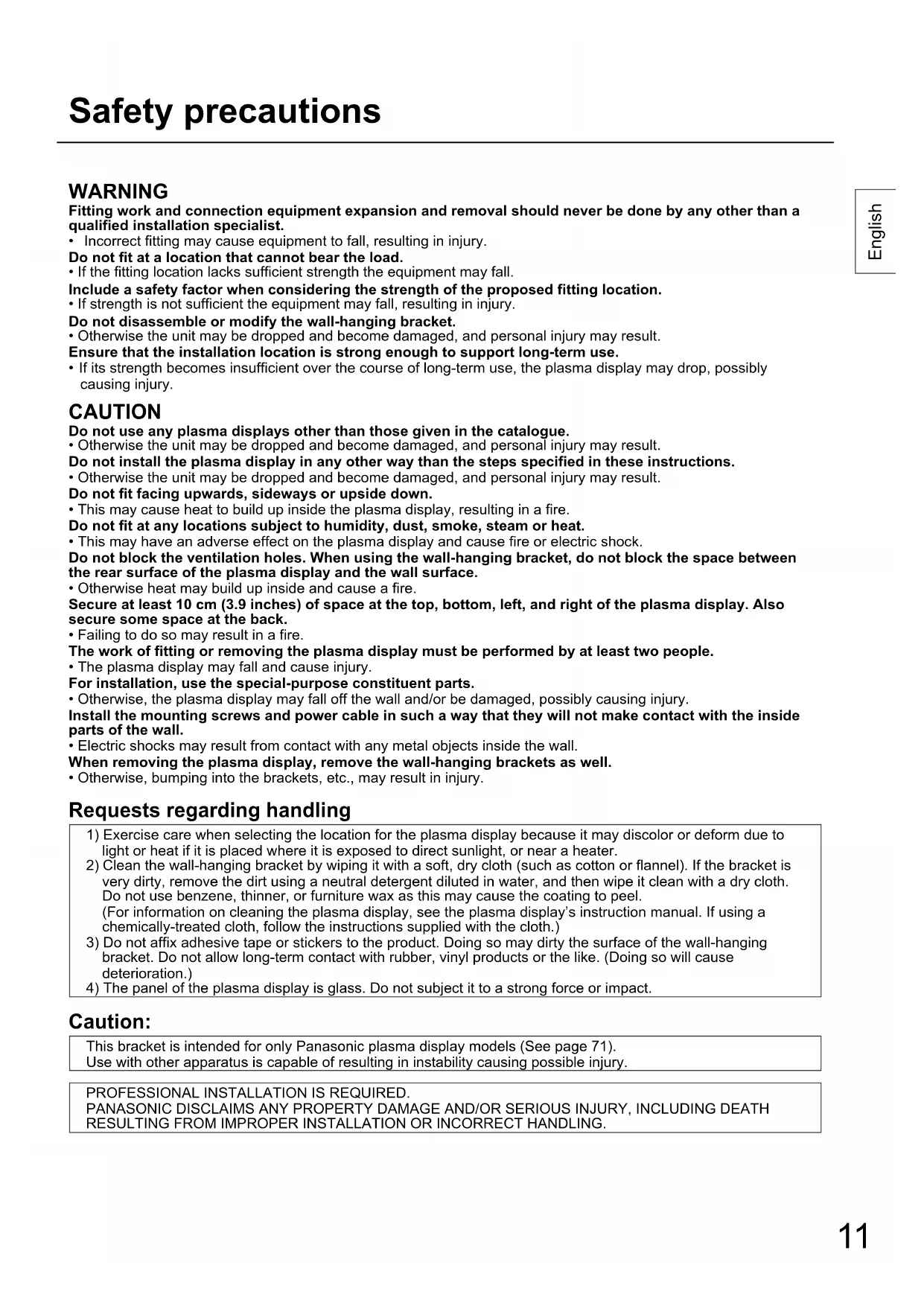
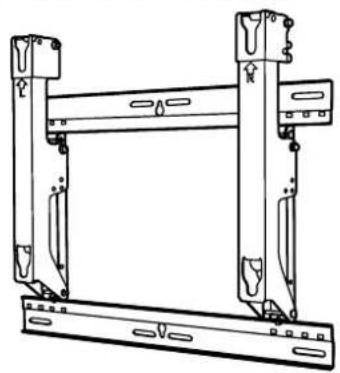
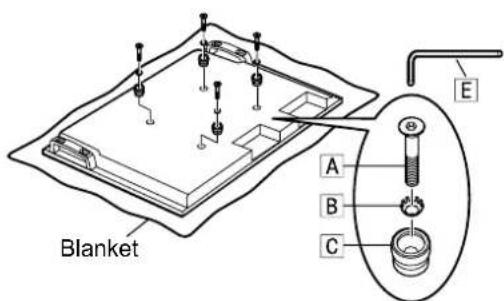
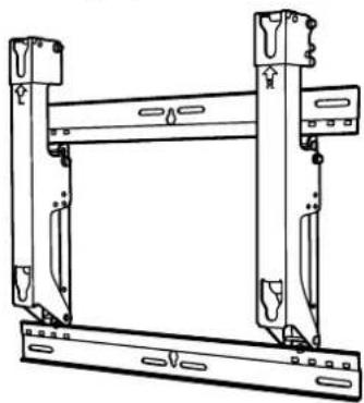
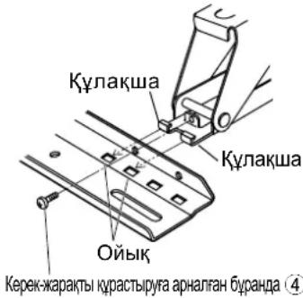
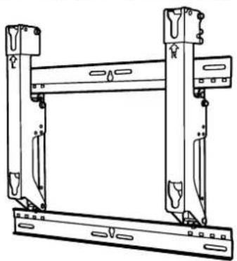
Parts used to assemble the wall-hanging bracket
① Base upper and lower fitting (2)
② Bracket base left fitting (1)
③ Bracket base right fitting (1)
④ Screw for assembling the fixture (4) M5x10

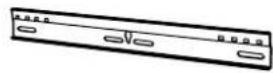
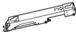
Parts used for installation
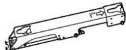
View of fully assembled fixture
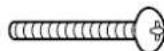
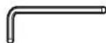
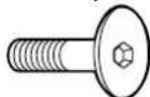
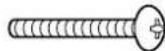
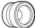
| A Allen head countersunk screw (4) M8×32 | D Screw for securing unit(2) M5×50 |
| B Dished toothed washer (4) | E Allen wrench (included tool) (1) |
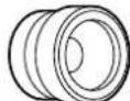
| C Insulation spacer (4) |
[The images shown in this manual are for illustrative purpose only.]
Precautions for wall-hanging bracket fitting
The wall-hanging bracket is for use in attaching a plasma display unit to a vertical wall for viewing. Do not fit to any surface other than a vertical wall.
To ensure correct plasma display performance and prevent trouble, do not fit at any of the following locations.
- Near sprinklers or fire/smoke detectors
- Where there is a risk of exposure to vibration or impact
- Near high-voltage wires or dynamic power supplies
Near sources of magnetism, heat, water vapor or soot - Locations exposed to air blown from heating equipment
- Where droplets of condensation from an air conditioner or other unit may form
Fit using techniques suited to the structure and materials of the fitting location.
Use commercially available screws with a nominal diameter of 6 mm (0.2 inches) that are suited to the wall material (wood, steel frame, concrete etc.) you are fitting the bracket to.
Ensure good air flow so that the ambient temperature does not exceed 40^ (104 F). Failure to do this may cause heat to build up inside the plasma display, resulting in malfunction.
Spread a soft blanket or cloth over the floor so that the plasma display and floor will not be marked or scratched during the assembly and installation work.
When screwing down the parts, ensure that the screws are neither insufficiently tightened nor over tightened.
For the plasma display power supply plug, use a power supply outlet that can be reached easily.
Take sufficient care and ensure safety around you when performing the installation work.
Do not install the plasma display underneath ceiling lamps (spotlights, halogen lamps, etc.). Otherwise, the cabinet may be bent or damaged by high heat.
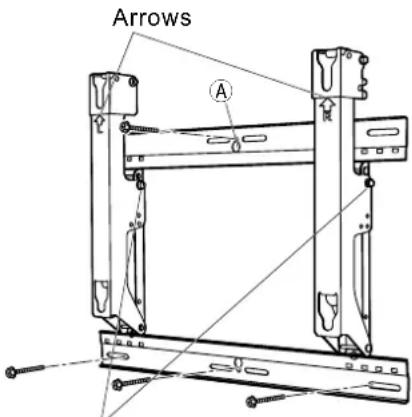
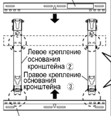
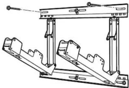
1. Assembling the wall-hanging bracket
- Assemble it according to the size of the plasma display.
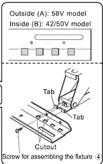
Place the base upper and lower fittings ① and base left ② and right ③ fittings as shown in the diagram. Insert the projecting parts (tabs) of the base left and right fittings into the cutouts of the base upper and lower fittings (two positions on right, and two on left), and secure the fittings with the screws for assembling the fixtures ④ 4).
(Tightening torque: 1.2 to 1.5N· m
Note
- Please hold the bracket base left and right fittings as you work with the assembled wall hanging bracket. Holding the base upper and lower fittings might deform this unit.
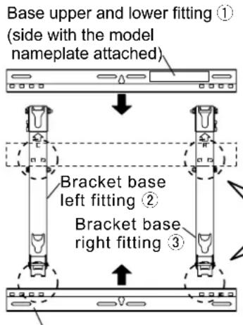
Base upper and lower fitting ①
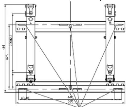
2. Checking the strength of the installation location
① The wall-hanging bracket weighs approximately 3.2kg (7.1 lbs). Refer to the instruction manual of the plasma display, and check the weight of the plasma display unit which will be fitted into the wall-hanging bracket.
Refer to the outline drawing of the wall-hanging bracket shown on the right, and check the wall strength at the six installation positions shown. If the strength at any of these positions is lacking, provide sufficient reinforcement.
Notes
- There are five pre-drilled mounting holes at the top and another five at the bottom of the wall-hanging bracket. Use the spare holes provided if wood or some other material is used for the wall and a sufficient level of mounting strength cannot be ensured by anchoring the fixture at the six positions shown on the right. However, bear in mind that, depending on which materials the mounting surface is made of, cracks may form on the surface if the screws are used at positions which are too close together.
- Do not mount or place any other product other than the plasma display on the fixture.
- For details on the dimensions applying when the plasma display is mounted, refer to the outline drawing (See page 71).
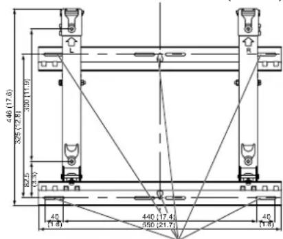
Unit: mm (inches)
Wall mounting holes (at 6 points)
Use the screws without fail to anchor the fixture.
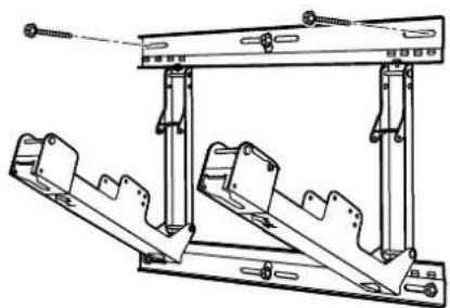
3. Installing the wall-hanging bracket on the wall
Notes
- If it is necessary to embed screws or nuts in the wall prior to installing the wall-hanging bracket because the wall is made of concrete or such other materials, determine the positions of the holes by fitting the actual wall-hanging bracket or calculating from the figures shown in the outline drawing, and then embed screws or nuts with a nominal diameter of 6mm (0.2 inches) or their equivalent. If you are embedding the screws, make sure they protrude from the wall surface by 10 to 15mm (0.4 to 0.6 inches).
- For the wall mounting screws, use commercially available screws with a nominal diameter of 6mm (0.2 inches) that are suited to the material/structure to which you are fitting the bracket.
- Anchor the screws in at least six locations.
- Check the strength of the mounting screws. Use screws that are sufficiently strong.
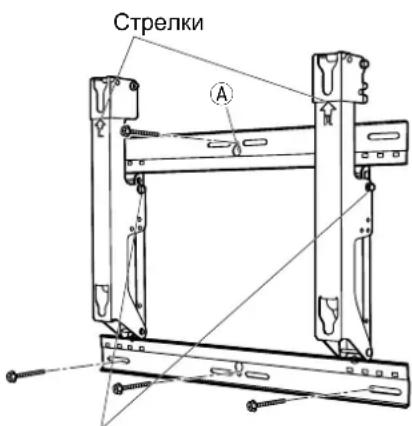
① Install the wall-hanging bracket so that the arrows indicated on it are pointing upward.
2 First of all, secure the screw in the upper center hole A.
Use a level to ensure that the bracket is not inclined at an angle, and screw the bracket into position using the three screw holes at the bottom.
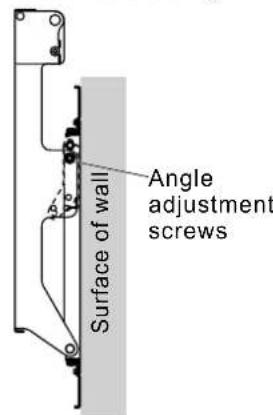
④ Remove the angle adjustment screws from the bracket base left ② and right ③ fittings, and open the bracket base left ② and right ③ fittings.
Angle adjustment screws
Screw the bracket into position using the screws at the remaining two screw holes at the top.
Use the angle adjustment screws, which were removed, to perform the angle adjustment of step 4.
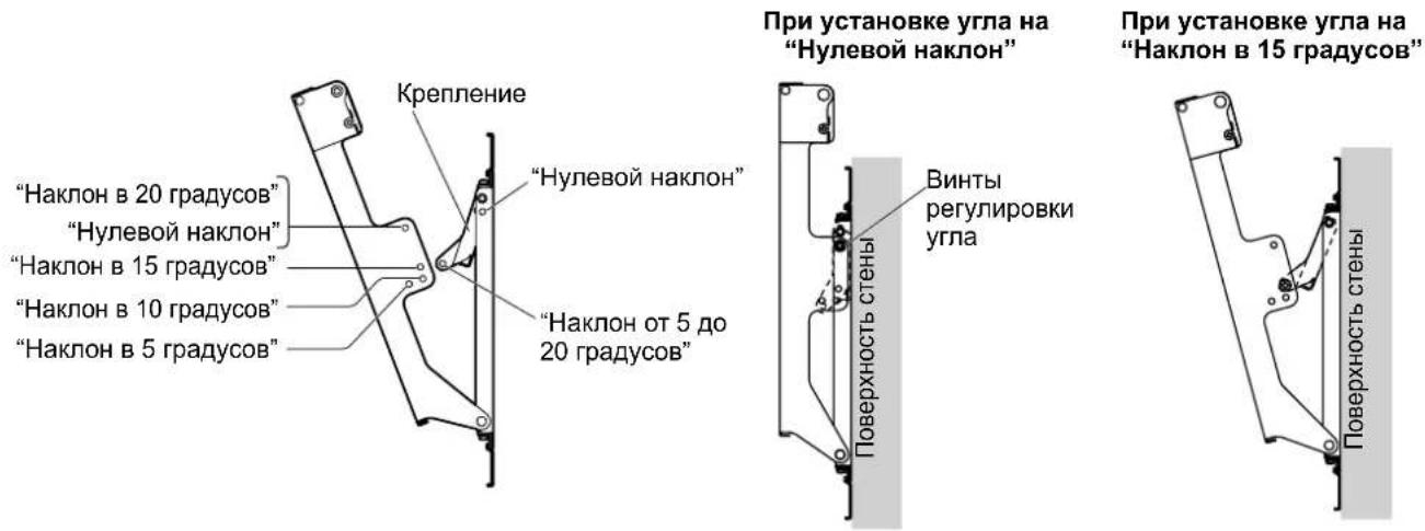
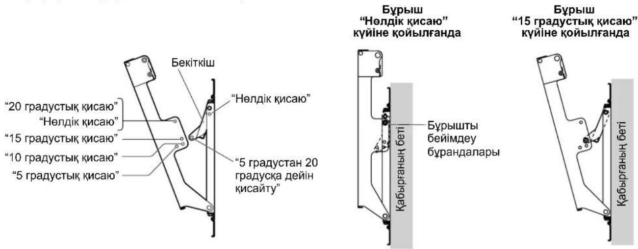
4. Adjusting the angle of the wall-hanging bracket
The angle of this wall-hanging bracket can be adjusted in 5-degree increments to one of five positions ranging from "Zero tilting" to "20-degree tilting".
The wall-hanging bracket is shipped from the manufacturing plant in the "Zero tilting" angle position. To change the angle, use the angle adjustment screws to change the position of the stay.
(Tightening torque: 1.2 to 1.5N· m
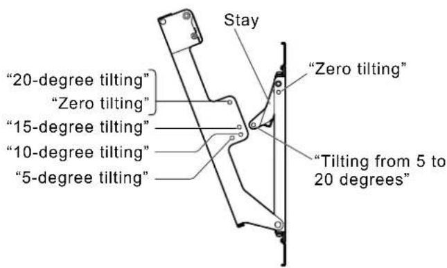
When the angle is set to "Zero tilting"
When the angle is set to "15-degree tilting"
Note
- When using some types of HDMI cables (RP-CDHG80 or RP-CDHG100) or PC cables, the cable may touch the wall and cause damage to the HDMI terminal or the PC input terminal on the plasma display.
In such a case, adjust the angle of the wall-hanging bracket so that no weight is applied to the cable.
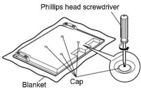
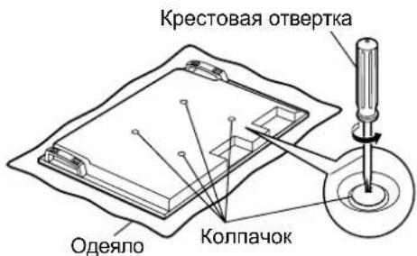
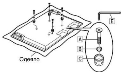
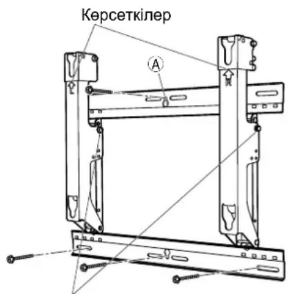
5. Preparing the plasma display
Attaching the insulation spacers
① Place the front surface of the plasma display on a clean cloth that has no dirt or foreign objects on it, and follow the procedure below. If the plasma display has any protruding parts, take care not to scratch or damage them.
② Remove the four caps from the plasma display using a Phillips head screwdriver.
Note
- Keep the caps that were removed in a safe place. (They will be required if you use the pedestal.)
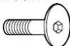
3 Using the supplied Allen wrench, mount the supplied 4 Allen head countersunk screws A, 4 dished toothed washers B and 4 insulation spacers C at the locations where the caps were removed as shown in the figure on the right. (Tightening torque: 3 to 4 N·m)
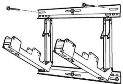
6. Mounting the plasma display onto the wallhanging bracket and connecting it to the other components
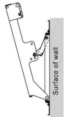
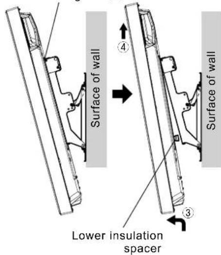
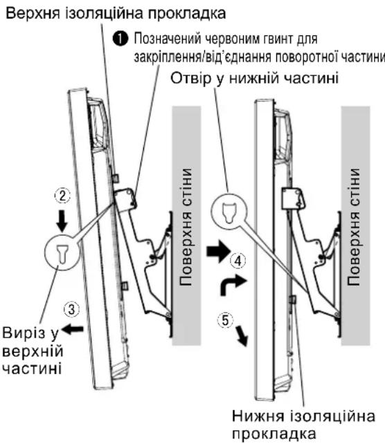
1 Remove the red-marked pivot fixing/releasing screws on the left and right (one at the left and one at the right).
② Fit the insulation spacers at the top of the plasma display onto the cutouts at the top of the wall-hanging bracket, and lower the plasma display.
Pull the plasma display toward you as shown in the figure on the right, and connect it to the power cord and the cables of other components.
After completing the connections, lift the plasma display slightly, and insert the lower insulation spacer into the hole at the lower part of the wall-hanging bracket.
⑤ Now lower the plasma display.
CAUTION
- If the plasma display is lifted too much, its top part will become disengaged from the wall-hanging bracket.
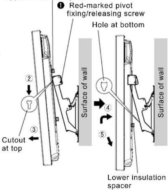
Upper insulation spacer
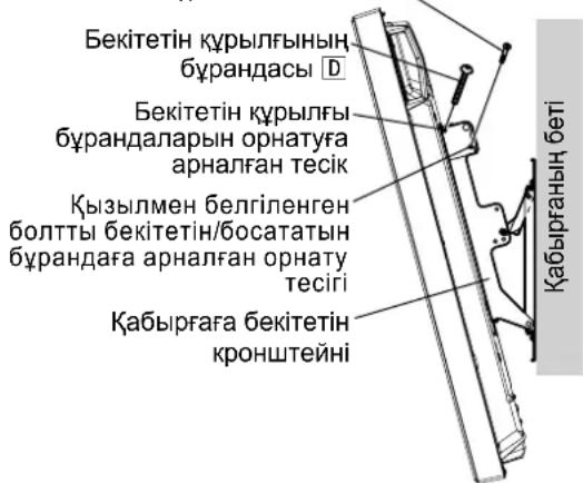
7. Anchoring the plasma display
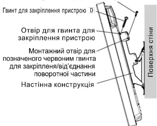
① Install the accessory screws for securing unit D (2) into the mounting holes of the screws for securing unit on the sides (left and right) of the wall-hanging bracket.
② Securely tighten the removed red-marked pivot fixing/releasing screws 1 (one at the left and one at the right) in the mounting holes of the red-marked pivot fixing/releasing screws on the sides of the wall-hanging bracket.
(Tightening torque: 1.2 to 1.5 N·m)
Note
- In order to prevent the plasma display from becoming disengaged from the wall-hanging bracket, the screws for securing unit D must be securely tightened at the left and right as far as their bases.
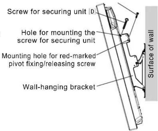
Red-marked pivot fixing/releasing screw
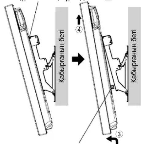
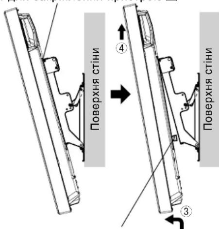
How to remove the plasma display from the wall-hanging bracket
① Remove the screws for securing unitD (one at the left and one at the right) which are mounted on the sides of the wall-hanging bracket.
② Disconnect the power cord and the wires connecting the plasma display to the other units.
③ While lifting the bottom part of the plasma display, pull the plasma display toward you.
After the bottom insulation spacers have been removed, continue lifting up the plasma display and remove it.
Note
- The plasma display needs to be lifted up approximately 4cm (1.6 inches) to be removed.
Screw for securing unit D
Warning
BbInHnIte yctAHOBky, nCNoIb3y TeXHOJOrnN, noDxOJaUne IaCTpyKTypb N MaTePnaJIOB MeCTaYcTaHOBKn.
IcnoIb3yIte HmeIOUneCBA npOaKe BnHTbHOMHaJIbHbIM dAmEtPOM 6 MM, NOxOJaue Ne dN MaTePnAna cTeHbI (DepeBO, CTaNbHOK KapKac, 6eToH nT.D.), B KOTOpM 6yDet 3aKpeIIeH KPOHtTeH.
O6ecneyTe xopouyo BeHTnJrauH, YTo6bI TeMnepaTpya OkpykaOuei cpeBHe Inpebbiua 40°C. B npOTNBOM Cnyae 3TO MOKeT npVBecTu K HAKONJIeHIO TEnJa BHyTpN Pna3MeHHoro DnCnner, YTO MOKeT Bbl3BaTb HeNCnPabBHOCTb.
PacTeJIte MraKoe OeIIO IIN TKAHb HA NOJy TaK, YTO6bl INa3MeHHbI DnCnne N NOI He IcnaKanCb H NoapanaNcB BO Bpempa60r no c6OpKe uycTaHOBe.
Bo Bpem npBnHvBaHnJeTanee cneDnte 3a Tem, YTO6bI BnHTbI He 6blnn 3aTAYbI HeOCTaTOHNO HHe 6blnn 3aTAYbI Ype3MepHo.
IcnoIb3yIte dna IwTeNCbHOBuINKuShHypa nITAHnI pNa3MeHHoro DnCnner JERKOIOCTynHyO cTeByo po3eTky.
PpIMTe DoCTaToHbIe Mepbl, UTo6bl ObecneHtB 63onacHocTb BOKpyr Ce6n npn BbInOnHeHH pa60 T no yctahOBke.
He yctaHabnBaIte 3OT nla3MeHHbI dncJIe HENOCpeCTBeHHO NOI NOTIOUHyIMN CBEtINbHkAMn (HaNPmep, NOD IcTOuHnKaMm MeCTHO OCBeueHn, PPOXKeTOpHOrO OCBeueHn INI rAIONeHHbIMN IaMnaM), KOTOpBle O6bIuHO BbIeJrHOT MHOrO TeIIa.
Takne DeiCTBnM Oryr npBecrK DeOpMaun Nnn NOBpeKdHIO PIACTMACCObIX DetaneN KOPnyca.
CobepnteeroBCOTBETCTBnCpa3MePOM Pna3MeHHoro Dncnner.
YcTaHOBnTe BepxHHee HnHXHee KpeNHeHHo OCHOBHn 1 N neBOe 2 N npaBoe 3 KpeNHeHHO OCHOBHn, KAK NOKa3aHO Ha CXeMe. BCTaBbTe BbICTyNaOHue qactn (fHKCaTOpbl) JEBORIO n npaBOrO KpeNHeHH OCHOBHn B BbIpe3bIBepxHero HnXHReo KpeNHeHH OCHOBHn (DBA MeCTa CnpBaN dBa cNeBa) n 3akpeNtTe KpeNHeHH BNHTAMn Dn rC6OpKn KpeNekHBIX npncnoc6JIeHH 4). (KpyTAAm MOMENT: ot 1,2 do 1,5 H·M)
PpMueaHne
-Пи BынОнHeHn paObT C sobpaHHbIM KPOHHTeHOM ДЯ КрелпЕнHa cTeHy, NOKAnIyIcTa, ДерКITE ЛевоE И павоE КрелпЕнЯ OCHOBaHЯ КрOHHTeHа. УдерЖИBaHme ВсХHero И НИХHero КрелпЕнЯ ОСНБАнМоКET ПИВecTи K DeФOPMaIg 6IOKa.
Bepxhee HnKHee KpenHne OCHOBAHNA ① (Ta CTOPOHa, Ha KOtopyO npKpeNHeHa nacOpTHa Ta6nUka c HAnMeHOBaHMe MoDeJI)
BepxHHe HnKHee KpeIeHne OCHOBaHna ①
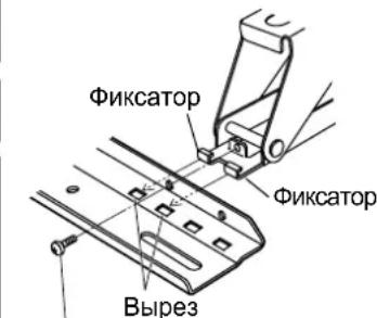
BHHT DIIa c6b0Km KpEeXHOro TnHcTOco6JIeHMe 4
BnHTbpepylnipOBKn yrrna
3aФнксypyTe KPOHHTeH Ha MecTe BnHTaMn B OCTaBuxxCBAByx OTBepCTnX DnBnHTOB, pACNOJIOKeHHbIX CBepxy.
6 NcnoB3yTe BnHTbI peryNupOBKn yrna, KOTOpBie 6bln ydaJIeHbI, DnB bInONHeHHa peryNupOBKn yrNa B nyHKte 4.
4. PerynipoBka yrna kpoHsTeHa dJa KpenJeHnHa cTeHy
YrOJ 3TOrO KpEnExHOr OyCTpoINCTBa DnI KpENNeHn Ha CTeHy MoKeT 6bITb yCTaHOBnE C WaROM B 5 rpaDycOB B ODHO n3 pAnI NOxKeHn, OT NOnoxeHn "HyneBOH HAKNoH" Do "HakNoH B 20 rpaDycOB".
Pn Otnpabke c 3aOda-n3roTOBtEny yron KPOHtEnHa dny KpenneHn Ha cTeHy yctAOBHe Hn "HyneBOHnaknoh".Iyra nCOnb3ynte BnHTbI perynpOBKn yrna, YTo6bl n3MeHnTB nOIOKeHne KpenneHn. (KpyTmN MOMENT: ot 1,2 do 1,5 H·M)
PpmeuHne
- PnncnoB0aHnn HeKoTOpbIX TINOB Ka6eJeHDMI (RP-CDHG80 nnn RP-CDHG100) nn Ka6eNe IIK, Ka6eNb MoKeT KacaTbCtHeBn Bb3BaTb NobpeKdEHepe pa3bema HDMI nnn BxOHoro pa3bema PIK Ha nna3MeHHOM dncnnee. B 3ToM cnyae NpOpyuye ron kpoHTeHa dn HacTeHHoro KpenneHra TaK, YTObHa Ka6eNb He npunaraoB daBneHne.
5. PodroTObKa pIa3MeHHoro dIscnpe
PpNkpennene H3OJIaunOHhbix npoknaodK
① PacnonoXnTe JnueByIO NOBepxHocTb NpA3MeHHoro DnCnJNe Ha YnCToN TKAHN 6e3 rpa3N NnN NOCTOPOHHX NpeDMTOB n CneDyIte npoueDpye, ONnCAHHo HnXe. EcnHa nnA3MeHHOM DnCnnee eCtB BbICTyNaIOUme DeTaN, No3a6ObTbTEcB O TOM, YTO6bl He NOnapanaTb N He NOBpeDHTb NX.
② C nOMOuIbIO KpeCTOBOI OTBepTKI ydaJIHTe C nIIa3MeHHORO dncnner YteIbe KOllnaUka
PpIMeuaHne
XpaHnTe CHrTbIe KOIIaHKn BHaJeXHom MeCTe. (Ohn noHaIO6BaTcR, ecnn bbl Byde Te nCNoIb3ObaTb NoCDTaBky.)
③ NcnoB3yra NOCTaBnREMbI TOpOBoB KInOu E, 3aKpeNITe 4 NOCTaBnREMbIX BnHTA C WeCTINrPaHNOI NOTaHNOI ROnOBKO A, 4 BbInyKnIbe 3y6uTBe IaNbB B n 4 N3OJIauHOHbIe npOKJaKn CB MeCTa, OTkyda 6bln CHrTbI KOJNaUKN, KAK NOKa3aHO Ha PNCyHKe CnpBa. (KpyTaeMOMeHT:OT3do4H·M)
③ KpoHwTeH Heri3iHi OH Jkak6ekitkiwi(1)
Kepek-kaapKbI Kypactbipyfa apHaanra6paHda4) M5×10

Ophaty ywiH naJaIaHaBbIaTbIH 6eJIweKTeP
ToJIbIK KypactbIpbIurHan 6ekITkiu KypblfBhHk Kepihici
A AJIbI KblpIbI Oblk 6actbl 6ypaHa4 (4) M8x32
DBekeTeTIN KypbIITbIHbH 6ypaHdacbl (2) M5×50
B Ticti deHec wai6a (4)

E Antbki KbiPbn KiT (XeK3y XnHaBbHa Kipei) (1)
C OkaynaftbIu Tecem (4)
[OcbI HcyckaynbikTaBcypeTTEp TEK MbicaI petiHde KepcetIITHe.]
Ka6bIpfara 6ekiTeiH KPOHHTeHdi KypacTbpy Ke3iHderi caKtbk waapanapbl
Ka6bipfara inetih KPOHwTeHH nna3MaIbIK dncnneHdi TIK ka6bipfara 6ekitin Kepy ywiH naJdaHaNbIa. TIK Ka6bipfadaH backa 6etke opHaTyBb 6oMaHbI3.
PnanaMbnIK DncnnneiH dypbic Kymbic icTeyih KaMTamacbi3 ety XeHe KaHdaJa6ip akaydbH anDbH any yuH MblHa Jepnepre opHaTnAbI3.
Cy wawkbwapdbH Hemece ept/TyTih DeTeKTopnapbHbH XaHbI
-Дірін Hemece COKKbI TnIO KayNi TəHETIN JekpneP
Korapbl KepHeyIcBIMdApdbH Hemece DnHaMkAkbK Kyat Ke3depiHiX KaHb
MarHnt epicepi, kblny, cy 6ybl Hemece Kyne lbfatbIH Jepnepdi KaHbi
KbInby XabdbfbHAn ypneHReh aya TneTIN Kepnep
Aya KOHdunuHepHeH HeMece 6aKa KypbIbIdaH 7bIfaTbIH KOHdeHcat TaMbInapbI Ty3iNetIH Xepnep
OphatJIaTbIH JepiH KpyblmbMeH MaTePnaJIbHa caikec KeNetIH aicTepeMHe opHaTbIbI3.
KpohTeH opHaTbIaTBIH Ka6bipraHbIH MaTePnaJIbHa (araU, 60NaT KapKac, 6eToH, T.6.) caikec KeNetiH, Ke3 KeIre H Jepde CaTbIaTH HOMHaJIdbI dJaMeTpI 6 MM 6ypaHdaapB1 naJdaHbIHbI3.
Cbiptkbi TemnepaTpaHbIH 40 C-tan acnaybi yuH OH bH XaKcbi XeNdeTIyH KAMTaMaCbI eTIH3. Θntnece, nna3MaBbIK dncnneH iuiHne Kbly naDa 6oBbI, OHbI 6y3blbHa ce6en 6onybl My
Kypacbpy KHe opHaTy Ke3iHne PnaMaBik DnCnnen MeH eEHe 6eJIr KaMaybI Hemece OnapbH Cbl3blmaybl yuiH eHRe Kymcak Kepne Hemece MaTATEcEN KOblb13.
BenweKTePdi 6paHdAmen 6ekTKeH Ke3e, 6paHdaIapdbIH 6oc Hemece TbIM KaTbI TapTbIMaybIH KaDaFaJNaHbI3.
Pna3MaBik Dncnneiin Kyat aWacbI yuH kon OHaJ KeTeIH 3eKtp po3eTkacbH naDaanahBHy3.
Ophaty Ke3iHde aca caKtbIKneH Kapan, Kayinc3diKi KaMTaMaCbI3 etIH3.
Пазmaындиспneид Te6e wamdapbHbIH (KapbIKaHdbIpfbIw npOKeKTopnapbIH, ranoreh wamdaPbIH, T.6.) actbHa opHaTnHaI3.
Tne, KaTbI KbIyadnKopnyc MaBicByHeme3aKbIMdanyblMymkIH.
1. Ka6bIPrAfa 6eKITeTIN KPOHHTeHdi KypacTbIpy
- ByhI pna3MaIbIK dncnneHIN KeJIeMIHe 6aIIaHaBcTbI KypacTbIPbIH3.
Heri3ri Kofapfbl XHe TEmHri 6eKTIkwepdi ① XHe Heri3ri con ② XHe OH XaK ③ 6eKTIwTePiOpHaJAcTbIPMaHbI3. Heri3dIn con XHe OH XaK 6eKTIwTePiH WbIFbIKb6BnweKTePi (KynakwanaP) Heri3dIn ycTHri XHe acTbIHfbI 6eKTIwTePiH ObIFbHa (OH XaKaTc EKI opBH XeHe CON XaKaTa eKI opBH) kipri3IH3 De, 6eKTIwTePi 6eKTIkw KypbINbHbI Kypactbpyra apHanrah bpaHdaanpMeH MbKTan 6eKITHi3 ④ (4).
(Taptydbin 6ypay MOMENTi:1,2-1,5 H·M)
EckepTne
KypactbipbIraH Ka6bpIraF a6kiTy KpoHtTeHIMeH Kymblc icTeReHde, KpoHtTeH Her3iHlCOn JAK KHe OH XaK 6eKtiKuTePi Yctan TypbHb. Her3dHnXoFarpFl KHe TEmehri 6eKtiKuTePi YctACAHI3, 6yN KpybIbHbN iuiHi 6y3blybl MyMKH.

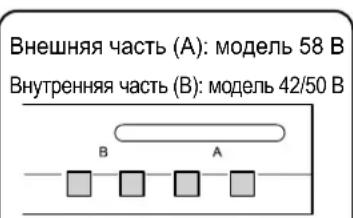
CbptbHa(A):58B ynrici IwHne (B):42/50B ynrici
2. OphatbIaTbIH kepDIn 6epiktirH Tekcepy
① Ka6biprara iTeiH KPOHwTeHHHcAImaFbI -waMaMeH 3,2 Kr. PJIa3MaJIbIK DnCnneDIn NaJdaNAnHybI HcyKayNbIFbIH Kapan, Ka6biprara iTeiH KPOHwTeHRe opHaTbJaTbIH PJIa3MaJIbIK DnCnneDIn CaImaFbIH TeKcepH3.
② OH KaKaTaBb Ka6bipra KPOHWeHiH KOHTypNbK cb36acBHa Kapan, KepceTInreH anTbI opHaTy opHBHdaFb Ka6bipFaHbH 6epiktirH TeKcepH3. Erep 6yI opbHapda 6epiktik XeTKiNikci 6oJca, XeTKiNikTi KyweTinyi H KaTAMacbI3 etIH3.
EckertneJep
Ka6bipfara iIeTIN KPOHtEHHIH XOFapfbl KaftbHa 6ec opHTy Teciri XHe TEmehri KaftbHa 6ec opHTy TECiB ap. Ka6bipfa aafTah Hemece baca MaTePnAnDaH XacanFaH BcONCA XHe OPAhTbNAtbIH XepDII MbIKTbJIbIFbI OH XaKta KepCetIInRe HAnTBOpBHHAN B6kTIy ApKbIbX KeTKlNkTI BOnMaCa, KocaNbI TECiKTEpDi NaidanaHbH3.DereHMHe, OPAH Ty BeHIN KaHdA MaTePnAnDaH XacanFaHbHn Kaai, 6ypaHdAnap 6bp-6ipHe TBIM XaKbIH OpBHpAp da naadanaHbHrF HxJaDnA, 6BeTte XapkTAP na DaONaTbHbH yMbITNaHb3.
- Bekity KpybIbIcIbHa Nla3MaIbIK DInCnNeiDeH 6aCa 6yIbIMDbI opHaTnaHbI3 Hemece opHaJAcTbIpMaHbI3.
-Плзмалын диспеловратынfaндколдahlлaitbн entwemdepr typabltonblk MJIIMETTEPDI KOTypblk cb36adaH KapaHb3 (71 6etTI KapaHb3).
Bipnik:MM
Ka6bipyfara 6ekitetih TecikTeep (6 HkyTepe)
Bekity KypbInfbicbH 6ekity yuiin, miDettI TypDe
bpaHdaIapdbI naIdaIaNbIHbI3.
3. Ka6biprara 6ekiteiH kpoHtEHHdi Ka6biprara opHaTy
EckertneJep
Ka6bipra 6eToH Hemece coJcKtbl 6acka MaTePnAnDapdAn XacanFaHbIKTaH, Ka6bipra KpOHuTHeHH opHaTnac 6ypbH 6ypaHdaIapDbH Hemece rAkaIaIapDb Ka6bipra Ra Kpri3y KaXet 6oNca, Ka6bipra KpOHuTHeHH iE3iH opHaty apkBnIb Hemece KHTyplbK cbl3aDa KepeCtiJIreh CypETTepHe EcenTe NbIFapBIn TECIKTePdiOpIHdApBH aHbIKTaHb3 Da, HomHnAbDi DnAmEtpi 6 MM Hemece OfAH 6Banama 6ypaHdAnap MeH raKanapDbI Kpri3H3. Erep 6ypaHdAnapDbI Kpri3in KaTKaHda, OlanDbI Ka6bipra 6eTIHeH 10-15 MM WbIFapBIn KObHb3.
Ka6biprara 6ekTeiH 6pyaHaIap yuHKn KPOHtEIn OphTaIaNtBn MaTePnaIra/ KypbIbIMFa caikec KeetIH catbIn aIbIHra HnAmETpi 6 MM 6ypaHaIapDbI naIdaIaNbIbI3.
-Бурандане кемпде aNTы Керден bypанб3.
- ByapaHdaIapabihMbIKbIbIbIFbIH TEKcepiH3. TeMbIKbIb ByapaHdaIapabHnJaIaHaHbHbI3.
① Ka6biprara 6ekiteiH kpoHtTeHHi OHdaftbI KepceTKinep KOFapbl Kapan TpyaTbIHdai etin opHaTbIHb3.
2AnbIMeH, XOFaPbI OPAHbI TecikTeri 6ypaHaDaHbI A TapTbHbI3.
③ KpOHTeH 6pybIbIHda 6yriin TyphaHbHa Ke3 XeTki3y yuH deHreynweriHn aadanaHbHb3 da, TEmeHderi yw 6ypaHa teciktepinKoJdaHbIn, KpOHTeHdi opHbHa 6ypan 6ekitih3.
④ KpohwTeH Heri3HH con ② XaHe OH ③ Ka6eKITKIHTepineH 6ypbIbI bEmdey 6ypaHaanapbH anbHbI3 da, KpOHTeH Heri3HH coJ ② XaHe OH ③ Ka6eKITkiTEpiH aWbHbI3.
BpybIbIb6eIMdEy bpaHdaIapbI
⑤ Yctideri Kanrah eki 6ypaHaTecikTePiHderi 6ypaHaJaNapdbI naJaHaBIn KPOHtEHHdi OPhbHa 6ypan 6ekitih3.
4-KaamHbH 6ypbIbH 6eIMdey yin aIbIHraH 6ypbiTbI 6eimdey 6ypaHaIapbH naJaIaHaBbIb3.
4. Ka6biprafa 6ekiteTIN kpoHwTeHHiH 6ypbIshbIH peTteHi3
BykKa6bipra KpoHwTeHHiH 6ypbIuBn 5 rpaDyCTbIK KaamdapMeH "Henik KncAHO" neH "20 rpaDyCTbIK KncAHO" apacbHdaI yu KaIbINTbH 6pIHe KoIbIn petTeyre bonaBl.
Ka6bipra kpoohTeHNI eHdipywi 3ayblTah xekTkiIreHde, 6pbli "Henik Kcaco" kaNbHa KoBlaNbIaBl. Byn 6ypbiWtBi e3repTy ywiH, pettey ywiH naadanaHbIaTbH 6paHdaanapdbI anbIn Tactan, 6eKtiWiTH opHATy Kyin e3reprhi3. (TaptydbH bypay MOMHI: 1,2-1,5 H·M)
EckepTne
- HDMI ka6eIbIepiH (RP-CDHG80 Hemece RP-CDHG100) Hemece Iep6ec KOMIbIopeK Ka6eJIbIepiH KeIbIepiH NaIaIaHaHReK3e, Ka6eIb Ka6bIpFara TIn, TeJeIuapdaBb HDMI yacbH Hemece PnA3MaNbIK DcNpeJderi Iep6ec KOMIbIOTep CINHaJIbIH Kipic YcBtH 3akIMdaybl MyMKIH.
Myndaa Kaafdaa, Ka6bipra KpoHnTeHinH 6ypbHbH Ka6eBre caJMaK TycneTIn eTin peTHei3.
Kb3bnMeH6enrHeH6oTTbI6KeTeTih/ 6ocataTbH 6paHa
Pna3MaIbIK DnCpIeNdi Ka6bIpra KpoHtTeHiHeH any
① Ka6bipra KpoHtEHHiHJXaKTapbHda opHaTbIraH 6eKITEIH Kypblfbl 6ypaHdAnapbH [D] (6ipeyH - coJ XaKaT, eKihwicH - OH XaKaT) WbHrFapbIn TaCTaHbI3.
② 3NeKtp WnHypbMeH nIa3MaJIbIK dncJIeNi6acka Kpyblfblnapfa KaIraTbIH CbIMapDbI aXbIpaTbIHbI3.
3 Nnma3MaNbIK dncnnneiH actbIHfbi KaFBH KETepreHde, nna3MaNbIK dncnnnei e3Hi3re kapaTapTBHbI3.
Tomehri apanbik Ka6aTTap anbHbIN 6oNraH COH, nla3MaJIbIK DnCnneDi TaBkTepein, OHBI Wewin aBbHbI3.
Eckertne
-ПиаMaJIbKДиСпл徳Дi Ушin any yшin YamAmeH 4 cm KeTepy KepeK.
BekiteiH KpybIfblhH 6paHaacbi D
TemeHri n30JnIyIbIK
apaka6aT
NONEPEDXKEHH
Yci po60TN 3 MOHTaxy, NiDKNIOUeHHRA 3'cNDyBaJIbHORO o6NaIHaHHra Ta BnDAJIeHHRA NOBHeH BIKOHByBaTH KBAIqDfIKOBAHn CneuaianCT.
- HehaJIeXHO BnKOHaHm MOHTaK MoKe cnpuHHnTu naIHnBa Hpo6y i npu3BeCTn Do TpaBMyBaHHra.
He BCTaHOBNIoTe Bnpi6 y Micqx, HenpndaTHnx IJIy BNTpmyBaHHHaBaHTaxeHb.
- YKUo MICue dIy MOHTaxy HeOCTaTHbO MiHcE, Bpi6 MoKe BNactN.
Iid yac po3paxynky miucnti Bn6paHoro mica nmoTaky bpaxoByte Koepicieht 6e3neKn.
- YKIO MUIHICTb MOHTaKy 6ynde HeIOCTaTHbOIO, Bnpi6 MoKe Bnactn i 3aBdaTn TpaBMn.
He po36npaIte I He moNphiKyIte HactiHnn KpoHHTeH.
LcMoKe npn3BecTn do nooKoJxehn a6o naHn npncpo o tprmaHH BHaCnIOK cboTO TpaBM.
IpekoHaTeC, 0o Miue, De MOHTyBaTmMeTbCra Bnpi6, DOCTaTHbO Miue dna 3a6e3neueHHr TpNBanoro BkOpncTaHHKpinHeHH.
- YkUaComMiHicb cTaHe HeoCTaTHbOIO,IIa3MOBn DInCpIe MoKe Bnactu 3abDAtu TpaBM.
3ACTEPEXEHH
BukopncToByte Inwe Ti nna3MObi dncnnei, kki HabeDehi y katano3i.
- IHaKHe Bnpi6 MoKe Bnacti i N0wKOJNTuC8, BOdHocac CnpNCHyOuH pN3NK OTPmHaHH TpaBM.
Iy yctaHOBNn nna3MOBOrO dncnner BnKOpNCToByte IInwe Ti di, rki HabeHb B cux IHctpyKciAx: He BCTaHOBNIOte npucpiy y kOdHn iHm cnoci6.
- IHaKSe Bnpi6 MoKe Bnactn i NpOkoDHTncsA, BoDHOcA CnpuHryHouHpy n3Nk OTpMaHHa TpaBM.
He BCTaHOBnIOTe nla3MOBn DnCnNeJ NlUcBOO CTOPOHO BROPy, Ha 6oCi a6o HxHbO O CTOPHO O DorOpn.
Lc moKe cnpuHHTn CkyuHHeHr TepNa BCEpeDHHI Pna3MOBOrO DnCnJIe, BHaCNIkOK YORo MOKe BHNKHyTn NOxExa.
He BCTAHOBNIHTE Bnpi6 y Micx i3 NiDbNueHO BOIoricTHo, CKynueHHm Nnny, DnMOM, BoaHOIO npoHO a60 BucOKOTo TEMnepatypoHO.
LCHHNI MOKytb HeratNBHO BnNbaTn Ha po60ty nla3MOBOrO dncnner, a TAKOX CTaTI npuHHIO NOJeki YpaxKeHH eNEKTpuHm Ctpymom.
He 6Nokyte BeHTnlaiHi OTbOpN. BnkOpncTOByOuH HactHHN KPOHsteH, He 3aKpNbAte npocTip mix 3aHbOIO NOBepxHeo nla3MOBOrO dncnner NOBepxHeo CTIHn.
- IhaKHe TeNIO MoKe HAcONuHTnCyrcepeDnHi CnpuHHTn POnkExy.
3aHitb xOa 6 10 cm BInbHoro npocTopy Buue, HxKue, npabOpuy i NibOpuy BiD nla3MOBOro dncnpe.
3aHitb TAKOK He6arato Micua 3a dnCnneM.
- HeDoTpmaHnI cxpeKOMeHdaI MoKe cnpuHHTn IoxExy.
Yci po60tn 3i BcTaHOBJIeHHa Ta dEmoHTaxy INa3MOBOrO dIcnIe MaOt b BkOHyBaTnC r OHaHMeHwe DbOMa IIOdbMn.
- IhaKwe nla3MOBn dncnne MoKe BnaCTn i 3aBdaTn TpaBMn.
BnKOpncToByTe dny yctaHOKn cneuaJIbHi cklaIObi YaCTHn.
- HeDToPMaHnH IeI BmOrn MoKe np3BecTn Do naIHn Pna3MOBOrO nncnIe 3i CTHN Ta/a6o Ioro yuKoJxHn, 3aBdaOnu TpaBMn NIOHi.
3akpinitb MOHTaXHi rBnHTn i Ka6eIb XKMBHeHHr TaKIM YHOM, 0o6 BOH He TOpKaHcR BHyTpiHix DeTaJIe CTiH.
- HeDToPMMaHnIeBmOrnMoKe npN3BeCTn Do ypaKeHHa eNeKtpuHm CtpyMOM BiD KOHTaKTy 3 6yDb-RAKMIMetaneBMn PpeDMtAMN BCEpEnHi CTiH.
3HimaOuH nIpa3MOBn dncnneJ, 3HimaTe TAKoK i HactiHHN KPOHHTeH.
- IhaKHe MoKHa BdApITcR O KPOHHTeHH ToIoo N OTPMaTn TpaBMy.
PekomeHdauciTCTOCOBHO NOBODXeHHA
1) YBaXHo BnBpaTte Micue dIy BCTaHOBLeHHN INa3MOBOrO DnCnJIeR, OCKINbKN BHaCNIIDOK II CBITna a60 TeIIa (y pa3i po3MiueHH no6m3y HarpBaJIbHnx npIaIbAIB a6o nIid nprMM COHcHMM pOMIHHM) BIn MOKe BTPaNTtKoJIip qN deOpMyBaTncb.
2) YnctbTe HactHHN KPOHSeH M'KIO cyxO TKaHNHO (HaPnKNaD, 6aOBHNO a6o φnanebeOIO).
Kaio KPOHSeH CNJbHO 3a6pydHeO, 3MnTe 6pyd BODHM PO3HNOM HeTpaJIbHO r MOUcOHO 3acOBy, a
notim BnTpIb KPOHSeH cyxO TKaHNHO. He BnKOpNCTOByTE 6eH30JI, PO3HNHK a6o BICK dIy Me6nIB,
Tomy Ioo IX 3actocyBaHH MoKe npn3BeCTn Do BiDnyuence HH AP6n NOKpTTT.
(IIo6 di3HaTncA, kY nCTHTn PnA3MOBn DnCnne, INB. IHCTpyKciIO Do DnCnpe. Ppr BnKOpNCtAHHi xIMiHOO
obpo6JeHO tKaAHHn CNoaTky yBaXHo npouHTaTe IHCTpyKciI do Hei.)
3) He npinkpinnrte IINKy cTpiuKy uH aninkn do Bnpo6y. LcMoKe npn3BecTu do 3a6pydHeHHra nobepxhi HactiHoro kpoHwTeHa. 3anobiraTe TpnbAlomy KOHTaKTy npncTPO 3 rymOBmN, BiHIOBmN Ta noDi6HMn Bnpo6amN. (Lc npns3Bepe Do noripweHra BnactnBOCTe npncTPO.)
4) PanaeB Ipa3MOBOrO DnCInner 3po6neHa 3i ckna. He DoKnaDaIte Do HeI HAdMipHy cnly N he NiDabAaTe II ydapam.
3ACTEPEKEHHJ:
LeynactiHnn KpOnuTeH np3HaueHn Iuwe nla3MOBx dncnneB Panasonic (DVB. cTOp. 71).
BnKopnCTaHn 3 iHIMM npnCTpOmn MoKe pN3BecTn Do HeHaJinHOi fikcaui, 10 MoKe CnpuHHnTn pn3NK OTPMaHn TpaBM.
MOHTAX IOBUNHEH BIKOHYBATNC CNEUJAICTAMN.
KOMNAHIA PANASONIC HE HECE BIDIOBIAJIbHOCTI 3A ByIb-RAI NOIKOJKEHHB JACHOCTI TA/ABO CEPIO3HI TPABMI, BKIOUAOCH CMEPTb, IIO E HACNI KOM HEBIIOBIHO HORO MOHTAXY ABO HENPABINbHOrO OBCJLYTOBYBAHHJ.
② JIIBE KpINJIeHHN OCHOBNKPOHHTeHa(1)
Bnrrn noBHicTHo 3i6paHOI KOHCTpykui
A TBNHT i3 yTONJNEHO rONOBKOHO i3 BHYTPIIWIM WecTMRPAHNNKOM (4) M8x32
TbHNTdN3aKpinHeHH npnctpo1o (2)M5×50
B YbirHyta 3y6chacta waia6a (4)

E TopeBn KIOU (BXOINTb DO KOMNNEKTY) (1)
C]IzolayiHa npoknaKa (4)
[3o6paXeHHy y cIbOMy nOciBnIKy NODaHbTcJNlWe 3 iJIIOCTpaTHBHOIO MeTOIO.]
3aTepeKhi 3axoDi nID Yac MoHTaKy HaCTIHHorO KPOHHTeHa
HactHHKPOHHTeIN BIKOPNCOTBycBcI Jn3aKpInJIeHH INa3MOBOrO DnCnJIeHa BEPTKaNbHi CTiHi npePrry. KPOHHTeIN DO3BOJAEbCMAHTyBaTn NIIe Ha BEPTKaNbHi CTiHi.
3a6e3neHTn HaleXHe yHKIOHyBaHHN Pna3MOBOrO DnCnIeR i 3ano6iRTN BUNKHeHHIO HeCnpabHOCTe, He cnID NORo BCTAHOBHOBATy TaNX Micx.
-Побиу розпскУваib a6о пожекнИx/ДиMOВИx DeTeKTopiB
B Miczex, de e p3nk Bv6yxy uepe3 Bi6paio a6o nowTOxN
-ПобиуВИСКОВОЛьнхДрOTIBaboHAmiHnx6NOKIЖИВLEHHA
-Побиу джерел Магнithor noя, tenna, napu abo caski
B Micua, 0o nndaTbca BnNBy nobitpy, 0o BnuBaetc3 onanIOBaHoro oHaHaHH
B Micx, De moKyb yTBOpOBaTncb kpani KOHeHcAty BiD KOHNuioHepB nobitpr a6o iHoro o6nHaHH
Iid yac MOHTaKy BnKOpNCTOByTe MeTOd KpInIeHnry, Akn Ha6iNbWe BiNObIaE cTpykTypi Ta MaTepiany NOBepxHi, HA kki BCTaHOBJIIOBAtUMETbCRA KPOHtTeH.
BnKOpncToByte HABHny npOAnky rBNHTN i3 HOMHaJIbHM diametpom 6 MM, kki BiIOBiaOTb MaTepiany CTIN, do koi KpInntbcra KPOHsteH (depeBO, ctaJeBa KOHCTpykui, 6eTOH TOIO).
CnD 3a6e3neHTN HopMaIbHy BeHTnlaIIO, Ioo TeMpepaTypa y npmiueHHi He nepeBnuSybana 40^ HeOpTpMaHnHa cboRo MoKe npn3BeCTn Do HAKONuHHe TennBa BCEpeDi Hi nla3MOBOrO dncnner i cnpuHHnTo Ioro HecnPabHicTB.
Po3TeiB M'ky KObpy a6o TKaHnHy Ha niJIOsI dIy TORO, 06 NiJ Yac cKnaDaHHra Ta MOHTaKy nJa3MOBn DnCnne Ta nIora He noopraanncr.
PnckpInneHHI deTaeH He 3aTaryTe rBHTN 3aHaTcNO CINbHO, aJe H eDOnyckaTe HeoCTaTHbOro 3aTaryBaHHra.
UTeNcIb shHypa kINBHeHH nIa3MOBOrO dIcIJIe NOBHeH IerKO dIcTaBAtNo eNEKtpuHoi pOsetKn.
Iicac BIKOHaHH po6it 3 MoTacky npdiinlby ybary 6eanei p6oohor Micra.
He MoxHa MOHTyBaTu NnA3MOBn DnCnne 6e3nocepHbO nID OCBITneHHa CTeni (TAKIM, JIK TOKOBi CBITNBHN, PPOXeKTOpn a6o ranoehrHi lamnn). Lc Me Moke npn3BeCTn Do deopmaui abo ykoDkeHHa nactMacobux Detanen Kopnyca.
(Moment 3aTaryBaHHa:3-4Hm)
6. MoHTaX pIIa3MOBOrO dIscnJeHa HactiHOMy KPOHUsTeHi Ta NiDkNIOUeHHa IHuX KOMNoHEHTiB
① BnkyTbNo3HaueHi YepBOHm TBnHTn Ia 3akpinneHa/Bid' EHaHH NOBOPoTHOI qACTHNI #IIBopyTu npabopyu (no ODHomy 3 Koxhoro 60ky).
② BctabTe i3onaiHn npoknaKn y Bepxhi qactnHi nla3MOBOrO DncnJe y Bnpi3n y Bepxhi qactnHi HactIHHoro KpOHwTeHa Ta onyctTb nla3MOBn dncnne.
③ NotarHITb pIa3MOBn DIncNney HAnpRMyD0 Ce6e, Ra noka3aHO Ha CXemipabopyu, Ta niKNoHcytB uHyp XnBHeHHr Ta Ka6eJI IHxk KomnoHEHTiB.
④ NicJn iNkIoueHn HnlaBHO nIDHIMt b nJa3MOBn DnCnJIe I BCTaBTe 130JauiHi npoknaDKn B OTbOpn y HxKHi YacTnHi HactIHHoro KPOHHTeHa.
⑤ Nicra yboro onycttbna3MOBn dncnne.
3ACTEPEXEHH
-ⅢAHTO CINbHO NIDHn Tn Pna3MOBn DnCnne, HORo BepxHa 即TnHa BiD'cHaEbCBAIDHACTHHOro KPOHTeHa.
7.3akpinlenHHnla3MOBOrO nucnJeA
① YcTaHObitdoaTkoBI rBHTnD (2) 3akpinneHH npncTpO B MOHTaxHI OTBOpN DnA rBHTIB nA 3akpinneHH npncTpO 36okIB (3 NIBORo Ta npaboro 6okIB) HactiHoro KPOHHTeHa.
② Haichiho 3aTaryHItb BuaJalehi No3haueHi cepBOHm TBnHTn Dnra 3akpinIeHHB/IdcDHaHnnoBOPoTHoi qactnHn (OINH JIBOpuy i OINn npabopyu) B MOHTaxHNX OTbopax dnn NO3haeHHx cepBOHm TBnHTiB dNra 3akpinIeHHB/IdcDHaHn noBOPoTHoi qactnHn 360kIB HactIHHO KPOHHTeHa. (Moment 3aTaryBaHH:1,2-1,5 H·M)
Pnmuitka
-Ⅲo6 nonepeDHTN BiD'EDHaHnrr Pna3MOBOrO Dncnner BiD HAcTINHO KPOHtTeHa, TBnHTn Dnra 3aKpInIeHHn IpiCtpoHO D MaOTb 6yTn ⅢJbHo 3aTgHyTmN 3 NIBORO Ta npABORO 60ky Do CBOIX OCHOB.
1 P03HaHeHn YepBOHM rBnHT dIy 3akpinHeHHr/Bid'EdHaHHNoBopOTHOuactHH
Bid'εdHaHnЯ Пla3MOBOrO dncnpey BiD hAcTiHHoro KPOHtEynHa
① BuaTb rBHTn dIy 3akpinHHeH npNCTpoIO (OIN npabopyu i OIN JIBOPuy), kI 6yno npKpInNeHO 3 60kIB HactHHoro KPOHtEHa.
② BiD'cHaHte uHyp XnBHeHHa Ta Ka6eNi, 3'cHyIb Nna3MOBn DnCnNe i3 IHuMn npIcTpoMn.
③ПиДимаюн HnxHIO qaCTHy Pna3MOBOrO nucnJIe,NotarHITb Ioro ha ce6e.
④ NicJI BnDAneHHH HnKHX i3OJauHnHn npOKJaOk npoObKyTe nIDHIMaTH nIa3MOBn DnCnnei 3HIMITb Ioro.
Пуимитka
- 3Hn nna3MOBn DnCnJe, noo Cn i nHrtn np6n3Ho Ha 4 cm.
Tbntdna3akpinienn npnctpoio D
HnXnI3oJauHa npoknaKa
警告
Wall-hanging bracket (Adjustable angle type)
External dimensions drawing
