D26501 - Planer DEWALT - Free user manual and instructions
Find the device manual for free D26501 DEWALT in PDF.
| Product Type | Planer |
| Brand | DeWalt |
| Model | D26501 |
| Rated Voltage | 230 V |
| Power Consumption | 1150 W |
| No-Load Speed | 11500 min⁻¹ |
| Base Length | 320 mm |
| Planing Width | 82 mm |
| Weight | 4 kg |
| Sound Pressure Level | 86 dB(A) |
| Sound Power Level | 95 dB(A) |
| Vibration Emission Value | 4.5 m/s² (uncertainty K=1.5 m/s²) |
| Max Cutting Depth | 4 mm (progressive adjustment, 0.1 mm per graduation) |
| Special Features | Constant speed and electronic brake |
| Blade Type | Reversible blades, replace in pairs |
| Parallel Guide | Side mounting, adjustable |
| Grooving Depth Stop | Included, height adjustable |
| Chip Ejection | Right or left, with ejector |
| Dust Extraction System | Adapter for dust bag or vacuum cleaner |
| Dust Bag | Included for K models, optional for others |
| Carrying Case | Included for K models |
| Double Insulation | Class II, no earth connection required |
| Warranty | 30-day satisfaction, 1 year free maintenance, 1 year parts |
| Package Contents | Planer, parallel guide, depth stop, wing nut, wrench, ejector, deflector (K models), dust bag (K models), vacuum adapter, carrying case (K models), manual, exploded drawing |
Frequently Asked Questions - D26501 DEWALT
Important: always replace blades in pairs.
User questions about D26501 DEWALT
0 question about this device. Answer the ones you know or ask your own.
Ask a new question about this device
Download the instructions for your Planer in PDF format for free! Find your manual D26501 - DEWALT and take your electronic device back in hand. On this page are published all the documents necessary for the use of your device. D26501 by DEWALT.
USER MANUAL D26501 DEWALT
English (original instructions)
Figure 6
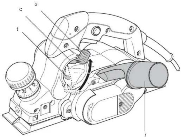
Figure 7
Figure 8
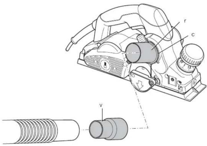
Figure 9
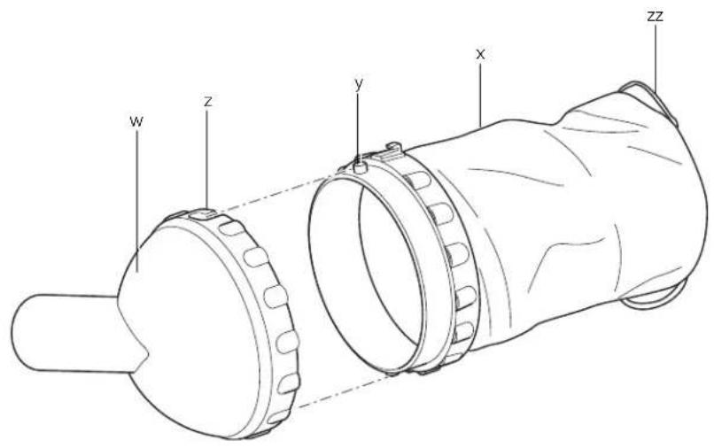
Figure 10
DANSK
H∅VLEMASKINE D26500, D26501
Tillykke!
RSEL: For at reducere
You have chosen a DEWALT tool. Years of experience, thorough product development and innovation make DEWALT one of the most reliable partners for professional power tool users.
Technical Data
| D26500 | D26501 | ||
| Voltage V 230 230UK & Ireland V 230/115 230/115 | |||
| Type | 1 | 1 | |
| Power output | W | 1050 | 1150 |
| No-load speed | min^1 | 13500 | 11 |
| Base length | mm | 320 | 320 |
| Planing width | mm | 82 | 82 |
| Weight | kg | 4 | 4 |
| L_pu (sound pressure) | dB(A) | 90 | 86 |
| K_pu (sound pressure uncertainty) | dB(A) | 3 | 3 |
| L_WD (sound power) | dB(A) | 99 | 95 |
| K_WD (sound power uncertainty) | dB(A) | 3.2 | 3.2 |
Vibration total values (triax vector sum) determined according to EN 60745:
| Vibration emission value a ah = | h m/s2 | 4.2 | 4.5 |
| Uncertainty K = | m/s2 | 1.5 | 1.5 |
The vibration emission level given in this information sheet has been measured in accordance with a standardised test given in EN 60745 and may be used to compare one tool with another. It may be used for a preliminary assessment of exposure.

WARNING: The declared vibration emission level represents the main applications of the tool. However if the tool is used for different applications, with different accessories or poorly maintained, the vibration emission may differ. This may significantly increase the exposure level over the total working period.
An estimation of the level of exposure to vibration should also take into account the times when the tool is switched off or when it is running but not actually doing the job. This may significantly reduce the exposure level over the total working period.
Identify additional safety measures to protect the operator from the effects of vibration such as: maintain the tool and the accessories, keep the hands warm, organisation of work patterns.
Fuses
| Europe | 230 V tools | 10 Amperes, mains |
| U.K. & Ireland | 230 V tools | 13 Amperes, in plugs |
| U.K. & Ireland | 115 V tools | 16 Amperes, in plugs |
Definitions: Safety Guidelines
The definitions below describe the level of severity for each signal word. Please read the manual and pay attention to these symbols.

DANGER: Indicates an imminently hazardous situation which, if not avoided, will result in death or serious injury.

WARNING: Indicates a potentially hazardous situation which, if not avoided, could result in death or serious injury.

CAUTION: Indicates a potentially hazardous situation which, if not avoided, may result in minor or moderate injury.
NOTICE: Indicates a practice not related to personal injury which, if not avoided, may result in property damage.

Denotes risk of electric shock.

Denotes risk of fire.
ENGLISH
EC-DeclarationofConformity
MACHINERY DIRECTIVE

D26500, D26501
DEWALT declares that these products described under "technical data" are in compliance with: 2006/42/EC, EN 60745-1, EN 60745-2-14.
These products also comply with Directive 2004/108/EC. For more information, please contact DEWALT at the following address or refer to the back of the manual.
The undersigned is responsible for compilation of the technical file and makes this declaration on behalf of DEWALT.

Horst Grossmann
Vice President Engineering and Product Development
WARNING: To reduce the risk of injury, read the instruction manual.
General Power Tool Safety Warnings

WARNING! Read all safety warnings and all instructions. Failure to follow the warnings and instructions may result in electric shock, fire and/or serious injury.
SAVE ALL WARNINGS AND INSTRUCTIONS FOR FUTURE REFERENCE
The term "power tool" in the warnings refers to your mains-operated (corded) power tool or battery-operated (cordless) power tool.
1) WORK AREA SAFETY
a) Keep work area clean and well lit.
Cluttered or dark areas invite accidents.
b) Do not operate power tools in explosive atmospheres, such as in the presence of flammable liquids, gases or dust. Power tools create sparks which may ignite the dust or fumes.
c) Keep children and bystanders away while operating a power tool. Distractions can cause you to lose control.
2) ELECTRICAL SAFETY
a) Power tool plugs must match the outlet. Never modify the plug in any way. Do not use any adapter plugs with earthed (grounded) power tools. Unmodified plugs and matching outlets will reduce risk of electric shock.
b) Avoid body contact with earthed or grounded surfaces such as pipes, radiators, ranges and refrigerators. There is an increased risk of electric shock if your body is earthed or grounded.
c) Do not expose power tools to rain or wet conditions. Water entering a power tool will increase the risk of electric shock.
d) Do not abuse the cord. Never use the cord for carrying, pulling or unplugging the power tool. Keep cord away from heat, oil, sharp edges or moving parts. Damaged or entangled cords increase the risk of electric shock.
e) When operating a power tool outdoors, use an extension cord suitable for outdoor use. Use of a cord suitable for outdoor use reduces the risk of electric shock.
f) If operating a power tool in a damp location is unavoidable, use a residual current device (RCD) protected supply. Use of an RCD reduces the risk of electric shock.
3) PERSONAL SAFETY
a) Stay alert, watch what you are doing and use common sense when operating a power tool. Do not use a power tool while you are tired or under the influence of drugs, alcohol or medication. A moment of inattention while operating power tools may result in serious personal injury.
b) Use personal protective equipment. Always wear eye protection. Protective equipment such as dust mask, non-skid safety shoes, hard hat, or hearing protection used for appropriate conditions will reduce personal injuries.
c) Prevent unintentional starting. Ensure the switch is in the off position before connecting to power source and/or battery pack, picking up or carrying the tool. Carrying power tools with your finger on the switch or energising power tools that have the switch on invites accidents.
d) Remove any adjusting key or wrench before turning the power tool on. A wrench or a key left attached to a rotating part of the power tool may result in personal injury.
e) Do not overreach. Keep proper footing and balance at all times. This enables better control of the power tool in unexpected situations.
f) Dress properly. Do not wear loose clothing or jewellery. Keep your hair, clothing and gloves away from moving parts. Loose clothes, jewellery or long hair can be caught in moving parts.
g) If devices are provided for the connection of dust extraction and collection facilities, ensure these are connected and properly used. Use of dust collection can reduce dust-related hazards.
4) POWER TOOL USE AND CARE
a) Do not force the power tool. Use the correct power tool for your application. The correct power tool will do the job better and safer at the rate for which it was designed.
b) Do not use the power tool if the switch does not turn it on and off. Any power tool that cannot be controlled with the switch is dangerous and must be repaired.
c) Disconnect the plug from the power source and/or the battery pack from the power tool before making any adjustments, changing accessories, or storing power tools. Such preventive safety measures reduce the risk of starting the power tool accidentally.
d) Store idle power tools out of the reach of children and do not allow persons unfamiliar with the power tool or these instructions to operate the power tool. Power tools are dangerous in the hands of untrained users.
e) Maintain power tools. Check for misalignment or binding of moving parts, breakage of parts and any other condition that may affect the power tool's operation. If damaged, have the power tool repaired before use. Many accidents are caused by poorly maintained power tools.
f) Keep cutting tools sharp and clean.
Properly maintained cutting tools with sharp cutting edges are less likely to bind and are easier to control.
g) Use the power tool, accessories and tool bits etc., in accordance with these instructions taking into account the
working conditions and the work to be performed. Use of the power tool for operations different from those intended could result in a hazardous situation.
5) SERVICE
a) Have your power tool serviced by a qualified repair person using only identical replacement parts. This will ensure that the safety of the power tool is maintained.
Additional Specific Safety Rules for Planers
- Wait for the cutter to stop before putting the tool down. An exposed cutter may engage the surface leading to possible loss of control and serious injury.
- Hold the power tool by insulated gripping surfaces only, because the cutter may contact its own cord. Cutting a "live" wire may make exposed metal parts of the power tool "live" and could give the operator an electric shock.
- Use clamps or another practical way to secure and support the workpiece to a stable platform. Holding the work by your hand or against the body leaves it unstable and may lead to loss of control.
- Wear a dust mask.
ResidualRisks
In spite of the application of the relevant safety regulations and the implementation of safety devices, certain residual risks cannot be avoided. These are:
- Impairment of hearing.
– Risk of personal injury due to flying particles. - Risk of burns due to accessories becoming hot during operation.
– Risk of personal injury due to prolonged use.
Markings on Tool
The following pictograms are shown on the tool:

Read instruction manual before use.
DATE CODE POSITION (FIG. 1)
The Date Code (aa), which also includes the year of manufacture, is printed into the housing.
Example:
2010 XX XX
Year of Manufacture
ENGLISH
Package Contents
The package contains:
1 Planer
1 Parallel fence
1 Rebating depth stop
1 Wing bolt
1 Spanner
1 Shavings ejector
1 Shavings deflector (K-models only)
1 Dustbag (K-models only)
1 Dust extraction adapter
1 Kitbox (K-models only)
1 Instruction manual
1 Exploded drawing
• Take the time to thoroughly read and understand this manual prior to operation.
- Check for damage to the tool, parts or accessories which may have occurred during transport.
Description (fi g. 1)
WARNING: Never modify the power tool or any part of it. Damage or personal injury could result.
a. On/off switch
b. Lock-off button
c. Shavings discharge outlet
d. Planing depth adjustment knob/front handle
e. Planing depth graduation
f. Parking shoe
CONSTANT SPEED FEATURE (D26501)
The constant speed feature maintains the cutting speed under load. This means less noise and a constant cutting speed. Moreover the speed will not increase dramatically when lifting the tool off the workpiece.
ELECTRONIC BRAKE (D26501)
The electronic brake stops the cutters upon releasing the on/off switch.
INTENDED USE
Your D26500/D26501 planers have been designed for professional planing of wood.
DO NOT use under wet conditions or in presence of flammable liquids or gases.
These planers are professional power tools.
DO NOT let children come into contact with the tool. Supervision is required when inexperienced operators use this tool.
Electrical Safety
The electric motor has been designed for one voltage only. Always check that the power supply corresponds to the voltage on the rating plate.

Your DEWALT tool is double insulated in accordance with EN 60745; therefore no earth wire is required.

WARNING: 115 V units have to be operated via a fail-safe isolating transformer with an earth screen between the primary and secondary winding.
If the supply cord is damaged, it must be replaced by a specially prepared cord available through the DEWALT service organisation.
Mains Plug Replacement (U.K. & Ireland Only)
If a new mains plug needs to be fitted:
- Safely dispose of the old plug.
- Connect the brown lead to the live terminal in the plug.
- Connect the blue lead to the neutral terminal.

IG: No connection is to be made to the earth terminal.
Follow the fitting instructions supplied with good quality plugs. Recommended fuse: 13 A.
Using an Extension Cable
If an extension cable is required, use an approved 3-core extension cable suitable for the power input of this tool (see technical data). The minimum conductor size is 1.5 mm ^2 ; the maximum length is 30 m.
When using a cable reel, always unwind the cable completely.
ASSEMBLY AND ADJUSTMENTS

NG: To reduce the risk of injury, turn unit off and disconnect machine from power source before installing and removing accessories, before adjusting or changing set-ups or when making repairs. Be sure the trigger switch is in the OFF position. An accidental start-up can cause injury.
Replacing the Cutting Blades (fi g. 2)
The cutting blades fitted on this tool are reversible. If both sides are worn, the cutting blades have to be replaced.

WARNING: Always replace the blades simultaneously.
- Carefully rotate the cutterhead (g) until the first blade becomes visible.
- Loosen the bolts (h) using the spanner supplied.
- Pull up the side guard (i).
- Slide the blade (j) out of its holder.
- Reverse the blade or replace it.
- Slide the blade into the holder. At the rebating side (i.e., the side where the side guard is mounted), the cutting blade must be flush with the planing shoe.
- Adjust the blade as described below.
- Tighten the bolts (h).
Repeat as for the other blade.
Adjusting the Blades (fi g. 2)
- Ensure the depth of cut is set at 0 mm.
- Check the position of the blade (j) at both ends. Use a flat object as a level across the planing shoe.
- The tip of the blade must be flush with the planing shoe surface.
- If adjustment is required, proceed as follows:
Turn each adjusting screw (k) in or out as necessary until the blade tip coincides with the planing shoe.
Adjusting the Depth of Cut (fi g. 1)
Turn the planing depth adjustment knob (d). One revolution of the adjustment knob equals a 4.0 mm change in depth.
One graduation corresponds to a depth of cut of 0.1 mm.
Attaching, Removing and Adjusting the Parallel Fence (fi g. 3)
The parallel fence (l) is used for optimum tool control on narrow workpieces. The parallel fence can be fitted to either side of the tool.
-
Assemble the parallel fence (l) in such way that the fence profile will provide guidance from the front of the tool until behind the cutterhead.
-
Fit the parallel fence to the threaded hole (m) from either side.
- Tighten the wing bolt (n).
To remove the parallel fence, remove the wing bolt.
TO ADJUST THE PARALLEL FENCE
- Loosen the wing nut (o).
- Adjust the fence so that there will be just enough area of the cutterhead left to cut the workpiece surface.
- Tighten the wing nut.
Attaching, Removing and Adjusting the Rebating Depth Stop (fi g. 4)
- Install the depth stop (p).
- Tighten the wing bolt (q) at the desired height in the threaded hole (m) using the scale.
To remove the depth stop, remove the wing bolt.
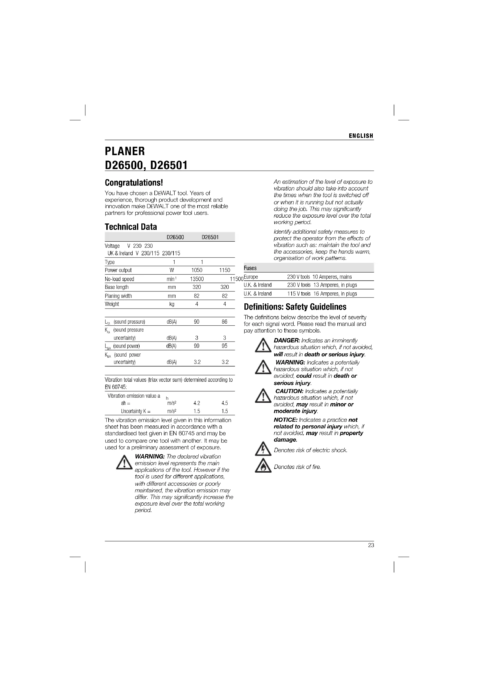
Fitting and Removing the Shavings Ejector (fi g. 5, 6)
The tool can be used for both left-hand and right-hand side shavings discharge.
For right-hand side shavings discharge (fig. 5), the tool can be used with or without the ejector. The ejector must be used in combination with the dust extraction adaptor when connecting a vacuum extractor.
- Push the ejector (r) into the right-hand side shavings discharge outlet (c) until it clicks in place.
- To remove the ejector, raise the lever (s) and pull out the ejector.
For left-hand side shavings discharge (fig. 6), the ejector must always be used.
- Raise the lever (s) to open the spring-loaded closure (l).
- Push the ejector (r) into the left-hand side shavings discharge outlet (c) until it clicks in place.
- Release the lever.
- To remove the ejector, raise the lever and pull out the ejector.
Dust Extraction (fi g. 7–9)

WARNING: When appropriate, connect a dust extraction system designed in compliance with the applicable directives regarding dust emission.
ENGLISH
The tool is supplied with an adapter for connecting a dustbag or a vacuum extractor. The dustbag is standard for K-models and available as an option for all other models.
- Fit the shavings ejector (r) into the outlet (c) as shown.
- Attach the dustbag (u) to the shavings ejector.
- Alternatively, connect the tool to a vacuum extractor using the adaptor (v).
ASSEMBLING THE DUSTBAG (FIG. 9)
- Assemble the dustbag by aligning the open ended slots (z) with the notches (y) and fitting the (w) deflector onto the bag (x).
- Turn the assembly clockwise to lock it in position.
- Release the loops (zz) to unfold the bag.
- Fit the dustbag as described above.
Prior to Operation
- Adjust the depth of cut.
- If necessary, fit and adjust the parallel fence.
- Attach the shavings ejector.
- Use sharp cutting blades only.
OPERATION
Instructions for Use
WARNING: Always observe the safety instructions and applicable regulations.
WARNING: To reduce the risk of serious personal injury, turn tool off and disconnect tool from power source before making any adjustments or removing/installing attachments or accessories.
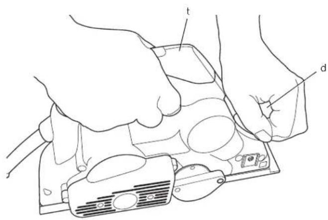
Proper Hand Position (fi g. 10)
WARNING: To reduce the risk of serious personal injury, ALWAYS use proper hand position as shown.
WARNING: To reduce the risk of serious personal injury, ALWAYS hold securely in anticipation of a sudden reaction.
Proper hand position requires one hand on the front handle (d), with the other hand on the main handle (t).
Switching On and Off (fi g. 1)
For safety reasons the on/off switch (a) of your tool is equipped with a lock-off button (b).
- Press the lock-off button to unlock the tool.
- To run the tool, press the on/off switch (a). As soon as the on/off switch is released the lock-off switch is automatically activated to prevent unintended starting of the machine.

WARNING: Do not switch the tool on or off when the cutters touch the workpiece or other materials.
Planing (fi g. 1)
- Switch the tool on.
- Slowly move the tool over the workpiece.

• The feed speed should not be too high, especially when using the maximum depth of cut and planing width.
• Remember that several shallow cuts are better than one deep cut.
• Always switch off the tool when work is finished and before unplugging.
The tool is equipped with a parking shoe (f). After switching off the tool can be put down without waiting for the cutters to come to a standstill.
Rebating
- Fit and adjust the parallel fence.
- Fit and adjust the rebating depth stop.
- Proceed as for planing.
Chamfering Edges
The V-grooves in the nose piece of the shoe enable you to chamfer edges.
Emptying the Dustbag (fi g. 7–9)
The amount of shavings collected in the dustbag can be determined from the transparent deflector.
- Remove the dustbag (u).
- Remove the deflector (w) from the bag (x) by turning it counter-clockwise.
- Empty the contents of the bag into a waste container.
-
Re-assemble the dustbag by aligning the open ended slots (z) with the notches (y) and fitting the deflector onto the bag.
-
Turn the assembly clockwise to lock it in position.
-
Re-fit dustbag.

Dust Extraction (fi g. 7–9)
When the tool is used indoor for extended periods of time, use a suitable dust extractor designed in compliance with the applicable directives regarding dust emission.
MAINTENANCE
Your DEWALT power tool has been designed to operate over a long period of time with a minimum of maintenance. Continuous satisfactory operation depends upon proper tool care and regular cleaning.

JG: To reduce the risk of injury, turn unit off and disconnect machine from power source before installing and removing accessories, before adjusting or changing set-ups or when making repairs.
Be sure the trigger switch is in the OFF position. An accidental start-up can cause injury.

Lubrication
Your power tool requires no additional lubrication.

Cleaning

WARNING: Blow dirt and dust out of the main housing with dry air as often as dirt is seen collecting in and around the air vents. Wear approved eye protection and approved dust mask when performing this procedure.

JG: Never use solvents or other harsh chemicals for cleaning the non-metallic parts of the tool. These chemicals may weaken the materials used in these parts. Use a cloth dampened only with water and mild soap. Never let any liquid get inside the tool; never immerse any part of the tool into a liquid.
Optional Accessories

WARNING: Since accessories, other than those offered by DEWALT, have not been tested with this product, use of such accessories with this tool could be hazardous. To reduce the risk of injury, only DEWALT, recommended accessories should be used with this product.
Consult your dealer for further information on the appropriate accessories.
Protecting the Environment

Separate collection. This product must not be disposed of with normal household waste.
Should you find one day that your DEWALT product needs replacement, or if it is of no further use to you, do not dispose of it with household waste. Make this product available for separate collection.

Separate collection of used products and packaging allows materials to be recycled and used again. Re-use of recycled materials helps prevent environmental pollution and reduces the demand for raw materials.
Local regulations may provide for separate collection of electrical products from the household, at municipal waste sites or by the retailer when you purchase a new product.
DEWALT provides a facility for the collection and recycling of DEWALT products once they have reached the end of their working life. To take advantage of this service please return your product to any authorised repair agent who will collect them on our behalf.
You can check the location of your nearest authorised repair agent by contacting your local DEWALT office at the address indicated in this manual. Alternatively, a list of authorised DEWALT repair agents and full details of our after-sales service and contacts are available on the Internet at: www.2helpU.com.
GUARANTEE
DEWALT is confident of the quality of its products and offers an outstanding guarantee for professional users of the product. This guarantee statement is in addition to and in no way prejudices your contractual rights as a professional user or your statutory rights as a private non-professional user. The guarantee is valid within the territories of the Member States of the European Union and the European Free Trade Area.
• 30 DAY NO RISK SATISFACTION GUARANTEE •
If you are not completely satisfied with the performance of your DEWALT tool, simply return it within 30 days, complete with all original components, as purchased, to the point of purchase, for a full refund or exchange. The product must have been subject to fair wear and tear and proof of purchase must be produced.
• ONE YEAR FREE SERVICE CONTRACT •
If you need maintenance or service for your DEWALT tool, in the 12 months following purchase, you are entitled to one service free of charge. It will be undertaken free of charge at an authorised DEWALT repair agent. Proof of purchase must be produced. Includes labour. Excludes accessories and spare parts unless failed under warranty.
• ONE YEAR FULL WARRANTY •
If your DEWALT product becomes defective due to faulty materials or workmanship within 12 months from the date of purchase, DEWALT guarantees to replace all defective parts free of charge or – at our discretion – replace the unit free of charge provided that:
• The product has not been misused;
- The product has been subject to fair wear and tear;
• Repairs have not been attempted by unauthorised persons;
• Proof of purchase is produced.
- The product is returned complete with all original components
If you wish to make a claim, contact your seller or check the location of your nearest authorised DEWALT repair agent in the DEWALT catalogue or contact your DEWALT office at the address indicated in this manual. A list of authorised DEWALT repair agents and full details of our after-sales service is available on the Internet at: www.2helpU.com
CEPILLADORA D26500, D26501
¡Enhorabuena!
Vice President Engineering and Product Development
BEWAAR ALLE WAARSCHUWINGEN EN INSTRUCTIES ALS TOEKOMSTIG REFERENTIEMATERIAAL
Stofafzuiging (afb. 7–9)

De stofzak legen (afb. 7–9)
Door de transparante deflector heen kunt u bepalen hoeveel spaanders er in de stofzak zitten.
Stofafzuiging (afb. 7–9)
1) SIKKERHET PÅ ARBEIDSOMRÅDET
SETTE PÅ ST∅VPOSEN (FIG. 9)
Vice President Engineering and Product
Development
DEWALT, Richard-Klinger-Strasse 11,
D-65510, Idstein, Germany
31.12.2009

DATUMKODPLACERING (FIG. 1)
VARVTALSKOMPENSERING (D26501)
natural_image
Pure horizontal line with endpoints and no text or symbols| Belgique et LuxembourgBelgië en Luxemburg | Black & Decker - DEWALTNieuwlandlaan 7, IZ Aarschot B156 Fax: +32 (0)015 - 15 47 9210B-3200 Aarschot | Tel: +32 (0)015 - 15 47 9211 | ||
| Danmark | DEWALTSiuseholmen | 2-4 | Tlf: | 70201511Fax: |
| 2450 Kobenhavn SV www.dewalt.dk | ||||
| Deutschland | DEWALTRichard-Klinger-Straße65510 | Idstein | Tel:Fax: | 06126-21-106126-21-2770www.dewalt.de |
| Ελλάς | Black & Decker (Hellas) S.A.Στράβωνος 7 & Bouλιαγμένης 159Γλυφάδα 16674, Αθήνα | Τηλ: (01) 8981-616Φαξ: (01) 8983-570Service: (01) 8982-630 | ||
| EspañaParque de Negocios "Mas Blau"Edificio Muntadas, c/Borgadá, 1, Of. A608820 El Prat de Llobregat (Barcelona) | DEWALTFax: 934 797 439www.dewalt.es | Tel: 934 797 400 | ||
| France5, allée des hêtresBP 30084, 69579 Limonest Cedex | DEWALTFax: 04 72 20 39 00www.dewalt.fr | Tel: 04 72 20 39 20 | ||
| SchweizSuisseSvizzera | DEWALTIn der Luberzen 408902 Urdorf | Tel: 01 - 730 67 47Fax: 01 - 730 70 67www.dewalt.ch | ||
| IrelandCalpe House Rock HillBlack Rock, Co. Dublin | DEWALTFax: 00353-2781811www.dewalt.ie | Tel: | 00353-2781800 | |
| ItaliaViale Elvezia 220052 Monza (Mi) | DEWALTFax: 039-2387592www.dewalt.it | Tel: | 800-014353 | |
| NederlandsJoulehof 124600 AB Børgon Op Zoom | Black & Decker - DEWALTFax: 0164 283100www.dewalt.nl | Tel: 0164 283000 | ||
| NorgePostboks 4814, Nydalen | DEWALTFax: 22 90 99 010422 Oslo | Tel: 22 90 99 00www.dewalt.no | ||
| ÖsterreichWorkzeugevertriebs GmbHErlaaerstraße 165, Postfach 320,1231 Wien | DEWALTFax: 01 - 66116 - 14www.dewalt.at | Tel: 01 - 66116 - 0 | ||
| PortugalRua Egas Moniz 173João do Estoril, 2766-651 Estoril | DEWALTFax: 214 66 75 75www.dewalt.pt | Tel: 214 66 75 00 | ||
| SuomiTeknikantie 1202150 Espoo, Finland | DEWALT OyFaksi: 0800 411 340www.dewalt.fi | Puh: 010 400 430 | ||
| DEWALT OyFax: 0800 411 340 | Tel: 010 400 430 | |||
| Teknikvägen 1202150 Esbo, Finland www.dewalt.fi | ||||
| SverigeBox 94431 22 Mölndal | DEWALTFax: 031 68 60 08www.dewalt.se | Tel: 031 68 61 00 | ||
| TürkiyeDefterdar Mah. Savaklar Cad. No:15Edirnekapi / Eyüp / İSTANBUL 34050 TÜRKİYE | Tel: 0212 533 52 55www.dewalt.com.tr | |||
| United Kingdom210 Bath RoadSlough, Berks SL1 3YD | DEWALTFax: 01753-57 21 12www.dewalt.co.uk | Tel: 01753-56 70 55 | ||
| N072598 | 04/10 | |||