DW735X - Planer DEWALT - Free user manual and instructions
Find the device manual for free DW735X DEWALT in PDF.
| Product Type | Thickness Planer |
| Brand | DEWALT |
| Model | DW735X |
| Power Supply | 120 V AC, 15 A |
| Frequency | 60 Hz |
| No Load Speed | 10 000 rpm |
| Feed Speed (Adjustable) | 4.3 m/min (14 ft/min) or 7.9 m/min (26 ft/min) |
| Max Planing Height | 152 mm (6 in) |
| Min Planing Height | 3 mm (1/8 in) |
| Max Planing Width | 325 mm (13 in) |
| Max Planing Depth | 3 mm (1/8 in) (for boards ≤ 152 mm wide) |
| Chip Ejection System | Fan Assisted |
| Carriage Lock | Integrated Automatic |
| Turret Stop (Positions) | 6 positions: 3, 6.5, 12.7, 19, 25.5, 32 mm |
| Built-in Circuit Breaker | 18 A, with reset button |
| Switch with Lock | Yes, lockable with padlock |
| Warranty | 3 years limited |
| Regular Maintenance | Cleaning, knife and brush replacement |
| Optional Accessories | Mobile stand DW7350, folding tables DW7351, knives DW7352, dust chute DW7353 |
Frequently Asked Questions - DW735X DEWALT
User questions about DW735X DEWALT
0 question about this device. Answer the ones you know or ask your own.
Ask a new question about this device
Download the instructions for your Planer in PDF format for free! Find your manual DW735X - DEWALT and take your electronic device back in hand. On this page are published all the documents necessary for the use of your device. DW735X by DEWALT.
USER MANUAL DW735X DEWALT
Definitions: Safety Alert Symbols and Words
This instruction manual uses the following safety alert symbols and words to alert you to hazardous situations and your risk of personal injury or property damage.
DANGER: Indicates an imminently hazardous situation which, if not avoided, will result in death or serious injury.
WARNING: Indicates a potentially hazardous situation which, if not avoided, could result in death or serious injury.
CAUTION: Indicates a potentially hazardous situation which, if not avoided, may result in minor or moderate injury.
(### without word) Indicates a safety related message.
NOTICE: Indicates a practice not related to personal injury which, if not avoided, may result in property damage.
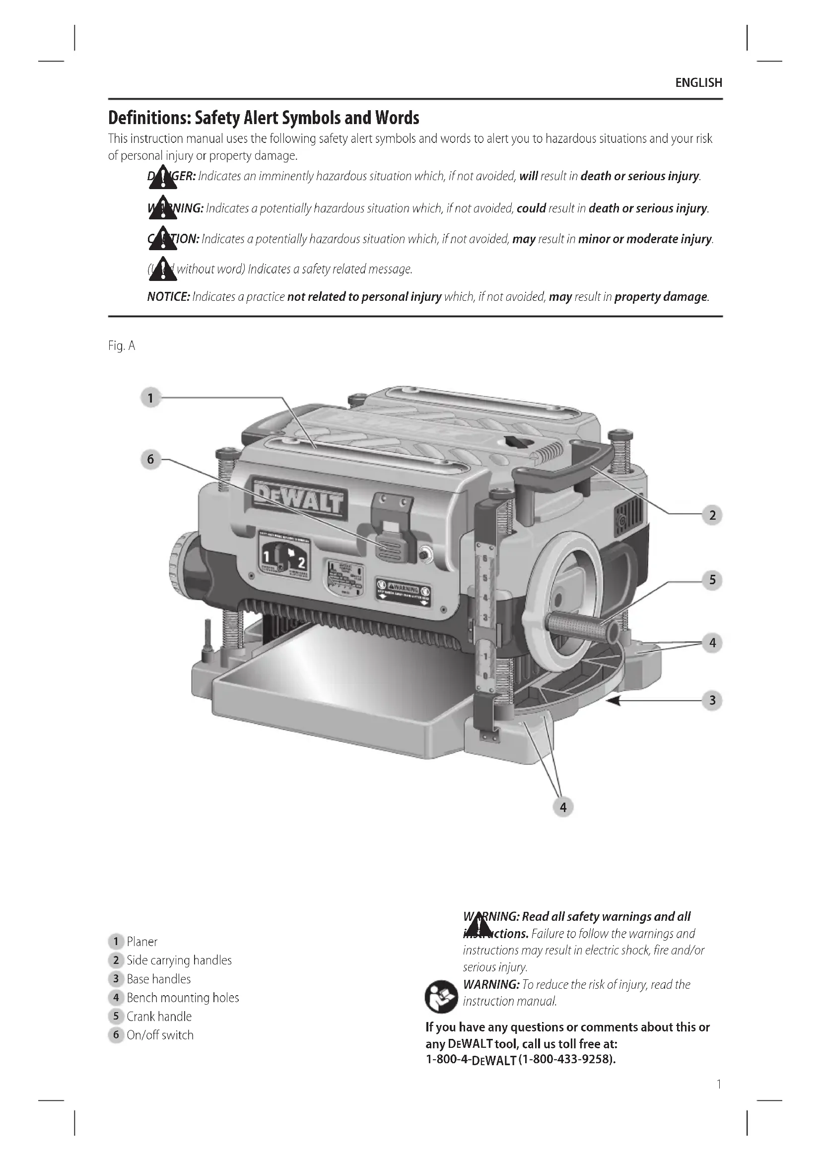
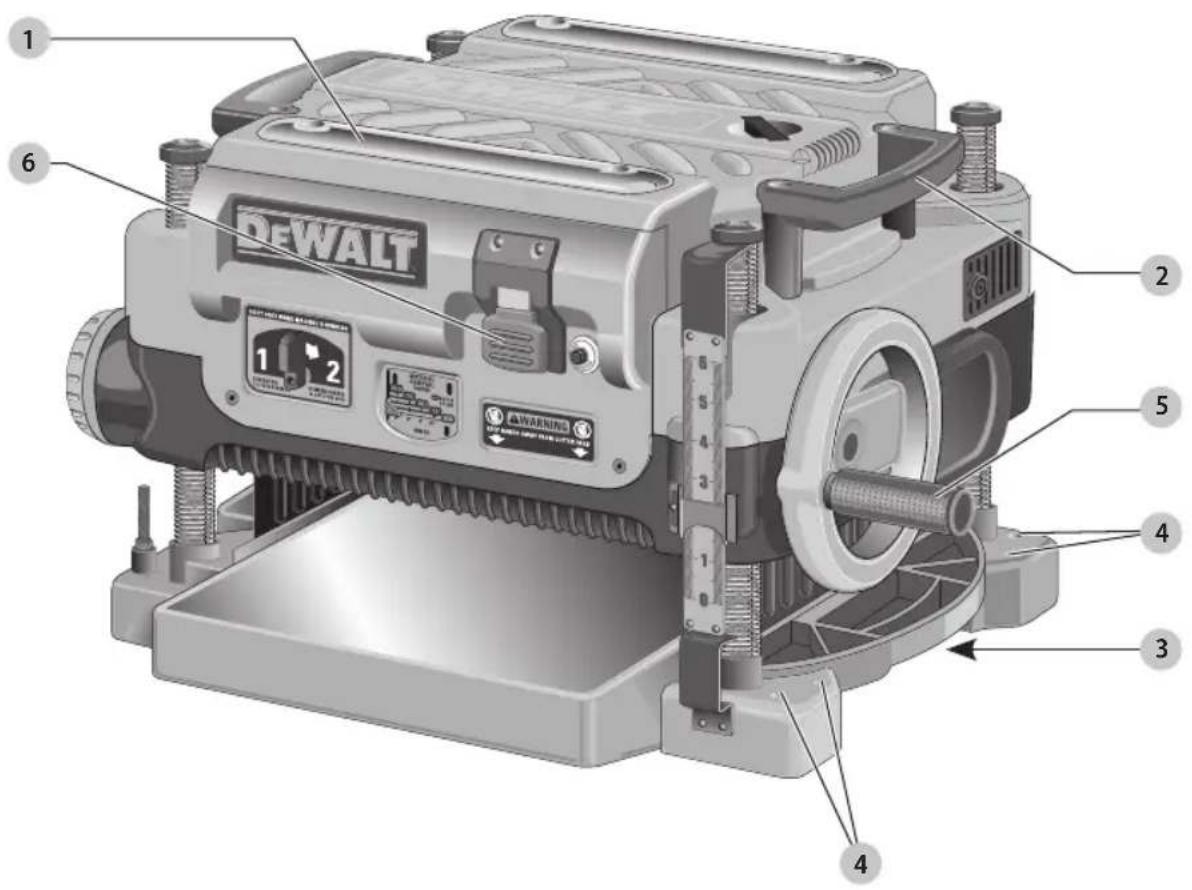
Fig. A
text_image
1 2 6 DEWALT 1 2 WARNING 4 3 41 Planer
2 Side carrying handles
3 Base handles
4 Bench mounting holes
5 Crank handle
6 On/off switch
WARNING: Read all safety warnings and all
instructions. Failure to follow the warnings and instructions may result in electric shock, fire and/or serious injury.

WARNING: To reduce the risk of injury, read the instruction manual.
If you have any questions or comments about this or any DEWALT tool, call us toll free at:
1-800-4-DEWALT(1-800-433-9258).
ENGLISH
General Power Tool Safety Warnings
WARNING: Read all safety warnings, instructions, illustrations and specifications provided with this power tool. Failure to follow all instructions listed below may result in electric shock, fire and/or serious injury.
SAVE ALL WARNINGS AND INSTRUCTIONS FOR FUTURE REFERENCE
The term "power tool" in the warnings refers to your mains-operated (corded) power tool.
General Safety Instructions
- KEEP GUARDS IN PLACE and in working order.
- REMOVE ADJUSTING KEYS AND WRENCHES. Form habit of checking to see that keys and adjusting wrenches are removed from tool before turning it on.
- KEEP WORK AREA CLEAN. Cluttered areas and benches invite injuries.
- DON'T USE IN DANGEROUS ENVIRONMENT. Don't use power tools in damp or wet locations, or expose them to rain. Keep work area well lighted. Always operate tool in a well-ventilated area free of combustible materials, gasoline or solvent vapors. If sparks come in contact with flammable vapors, they may ignite, causing fire or explosion.
- KEEP CHILDREN AWAY. All visitors should be kept safe distance from work area.
- MAKE WORKSHOP KID PROOF with padlocks, master switches, or by removing starter keys.
- DON'T FORCE TOOL. It will do the job better and safer at the rate for which it was designed.
- USE RIGHT TOOL. Don't force tool or attachment to do a job for which it was not designed.
- USE PROPER EXTENSION CORD. Make sure your extension cord is in good condition. When using an extension cord, be sure to use one heavy enough to carry the current your product will draw. An undersized cord will cause a drop in line voltage resulting in overheating and loss of power. The Minimum Gauge for Cord Sets table shows the correct size to use depending on cord length and nameplate ampere rating. If in doubt, use the next heavier gauge. The smaller the gauge number, the heavier the cord. When operating a power tool outside, use an outdoor extension cord marked "W-A" or "W." These cords are rated for outdoor use and reduce the risk of electric shock.
- WEAR PROPER APPAREL. Do not wear loose clothing, gloves, neckties, rings, bracelets, or other jewelry which may get caught in moving parts. Nonslip footwear is recommended. Wear protective hair covering to contain long hair. Air vents often cover moving parts and should also be avoided.
-
ALWAYS USE SAFETY GLASSES. Also use face or dust mask if cutting operation is dusty. Everyday eyeglasses only have impact resistant lenses, they are not safety glasses.
-
SECURE WORK. Use of clamps or a vise to hold work when practical. It's safer than using your hands and it frees both hands to operate tool.
- DON'T OVERREACH. Keep proper footing and balance at all times.
- MAINTAIN TOOLS WITH CARE. Keep tools sharp and clean for best and safest performance. Follow instructions for lubricating and changing accessories.
- DISCONNECT TOOLS before servicing; when changing accessories, such as blades, bits, cutters, and the like.
- REDUCE THE RISK OF UNINTENTIONAL STARTING. Make sure switch is in off position before plugging in.
- USE RECOMMENDED ACCESSORIES. Consult the instruction manual for recommended accessories. The use of improper accessories may cause risk of injury to persons.
- NEVER STAND ON TOOL. Serious injury could occur if the tool is tipped or if the cutting tool is unintentionally contacted.
- CHECK DAMAGED PARTS. Before further use of the tool, a guard or other part that is damaged should be carefully checked to determine that it will operate properly and perform its intended function—check for alignment of moving parts, binding of moving parts, breakage of parts, mounting, and any other conditions that may affect its operation. A guard or other part that is damaged should be properly repaired or replaced.
- DIRECTION OF FEED. Feed work into planer according to direction of feed arrows on top of the unit.
- NEVER LEAVE TOOL RUNNING UNATTENDED. TURN POWER OFF. Don't leave tool until it comes to a complete stop.
Safety Rules for Surface Planers
WARNING: Failure to follow these rules may not in serious personal injury.
- Do not operate this machine until it is completely assembled and installed according to the instructions. A machine incorrectly assembled can cause serious injury.
- Obtain advice from your supervisor, instructor, or another qualified person if you are not thoroughly familiar with the operation of this machine. Knowledge is safety.
- Follow all wiring codes and recommended electrical connections to prevent shock or electrocution.
- Keep knives sharp and free from rust and pitch. Dull or rusted knives work harder and can cause kickback.
- Never turn the machine "ON" before clearing the table of all objects (tools, scraps of wood, etc.). Flying debris can cause serious injury.
- Never turn the machine "ON" with the workpiece contacting the cutterhead. Kickback can occur.
- Secure the machine to a supporting surface to prevent the machine from sliding, walking or tipping over.
- Be sure that the cutter knives are mounted as described in the instruction manual and check that
all bolts are firmly tightened before connecting unit to power source.
- Avoid awkward operations and hand positions. A sudden slip could cause a hand to move into the knives.
- Keep arms, hands, and fingers away from the cutterhead, the chip exhaust opening, and the feed rollers to prevent severe cuts.
- Never reach into the cutterhead area while the machine is running. Your hands can be drawn into the knives.
- Do not stand in line with the workpiece. Kickback can cause injury.
- Allow the cutterhead to reach full speed before feeding a workpiece. Changing speeds while planing can cause kickback.
- When planing bowed stock, place the concave (cup down) side of the stock on the table and cut with the grain to prevent kickback.
- Do not feed a workpiece that is warped, contains knots, or is embedded with foreign objects (nails, staples, etc.). Kickback can occur.
- Do not feed a short, thin, or narrow workpiece into the machine. Your hands can be drawn into the knives and/or the workpiece can be thrown at high speeds. See the Operation section of this instruction manual for details.
- Do not feed a workpiece into the outfeed end of the machine. The workpiece will be thrown out of the opposite side at high speeds.
- Remove shavings only with the power "OFF" and the cutterhead stopped to prevent serious injury.
- Properly support long or wide work pieces. Loss of control of the workpiece can cause serious injury.
- Never perform layout, assembly or set-up work on the table/work area when the machine is running. Serious injury will result.
- Turn the machine "OFF", disconnect it from the power source, and clean the table/work area before leaving the machine. Lock the switch in the "OFF" position to prevent unauthorized use. Someone else might accidentally start the machine and cause injury to themselves or others.
- Additional information regarding the safe and proper operation of power tools (i.e. a safety video) is available from the Power Tool Institute, 1300 Sumner Avenue, Cleveland, OH 44115-2851 (www.powertoolinstitute.com). Information is also available from the National Safety Council, 1121 Spring Lake Drive, Itasca, IL 60143-3201. Please refer to the American National Standards Institute ANSI 01.1 Safety Requirements for Woodworking Machines and the U.S. Department of Labor Regulations.
Supplemental Safety Rules for Planers
- To avoid injury, never rotate the cutterhead directly with your hands.
- Keep hands away from the underside of the cutterhead carriage.
- Never clear clogs, make cutter knife replacement, or any other repairs/adjustments with unit plugged in.
• Make certain that the switch is in the "OFF" position before connecting plug to a power source. - Stay alert—never operate the unit when tired or under the influence of drugs, alcohol, or medication.
- Do not use in dangerous environments. Do not use near flammable substances, in damp or wet locations, or expose to rain.
- Never plane material which is shorter than 12" (304.8 mm) narrower than 3/4" (19.05 mm), or wider than 12" (304.8 mm) or thinner than 1/2" (12.7 mm).
- Exhaust chute: remove shavings with brush or vacuum after power has been shut off and cutterhead has stopped rotating.
• Always locate planer with proper clearance on the outfeed side of the unit to prevent pinching or binding of the workpiece against any obstacle. - Maintain the proper relationships of infeed and outfeed table surfaces and cutterhead knife path.
- Lock the speed setting securely before feeding the workpiece through the machine. Changing speeds while planing can cause kickback.
Additional Safety Information
WARNING: Never modify the power tool or any part of all. Damage or personal injury could result.
WARNING: ALWAYS use safety glasses. Everyday eyeglasses are NOT safety glasses. Also use face or dust mask if cutting operation is dusty. ALWAYS WEAR CERTIFIED SAFETY EQUIPMENT:
• ANSI Z87.1 eye protection (CAN/CSA Z94.3),
• ANSI S12.6 (S3.19) hearing protection,
• NIOSH/OSHA/MSHA respiratory protection.
WARNING: Some dust created by power sanding, sanding, grinding, drilling, and other construction activities contains chemicals known to the State of California to cause cancer, birth defects or other reproductive harm. Some examples of these chemicals are:
- lead from lead-based paints,
• crystalline silica from bricks and cement and other masonry products, and
• arsenic and chromium from chemically-treated lumber.
Your risk from these exposures varies, depending on how often you do this type of work. To reduce your exposure to these chemicals: work in a well ventilated area, and work with approved safety equipment, such as those dust masks that are specially designed to filter out microscopic particles.
English
- Avoid prolonged contact with dust from power sanding, sawing, grinding, drilling, and other construction activities. Wear protective clothing and wash exposed areas with soap and water. Allowing dust to get into your mouth, eyes, or lay on the skin may promote absorption of harmful chemicals.
WARNING: Use of this tool can generate and/or disperse dust, which may cause serious and permanent respiratory or other injury. Always use NIOSH/OSHA approved respiratory protection appropriate for the dust exposure. Direct particles away from face and body.
WARNING: Always wear proper personal hearing protection that conforms to ANSI S12.6 (S3.19)
during use. Under some conditions and duration of use, noise from this product may contribute to hearing loss.
Power Connections
A separate electrical circuit should be used for your machines. This circuit should not be less than #12 wire and should be protected with a 20 Amp time lag fuse.
NOTE: Time delay fuses should be marked "D" in Canada and "T" in the US. If an extension cord is used, use only 3-wire extension cords which have 3-prong grounding type plugs and matching receptacle which will accept the machine's plug. Before connecting the machine to the power line, make sure the switch (or switches) is in the "OFF" position and be sure that the electric current is of the same characteristics as indicated on the machine. All line connections should make good contact. Running on low voltage will damage the machine.
DANGER: Do not expose the machine to rain or open the machine in damp locations.
MOTOR SPECIFICATIONS
Your machine is wired for 120 Volts, 60 HZ alternating current. Before connecting the machine to the power source, make sure the switch is in the "OFF" position.
Grounding Instructions
DANGER: This machine must be grounded while in use to protect the operator from electric shock.
-
All grounded, cord-connected machines:
-
In the event of a malfunction or breakdown, grounding provides a path of least resistance for electric current to reduce the risk of electric shock. This machine is equipped with an electric cord having an equipment-grounding conductor and a grounding plug. The plug must be plugged into a matching outlet that is properly installed and grounded in accordance with all local codes and ordinances.
- Do not modify the plug provided - if it will not fit the outlet, have the proper outlet installed by a qualified electrician.
- Improper connection of the equipment-grounding conductor can result in risk of electric shock. The conductor with insulation having an outer surface that is green with or without yellow stripes is the
equipment-grounding conductor. If repair or replacement of the electric cord or plug is necessary, do not connect the equipment-grounding conductor to a live terminal.
- Check with a qualified electrician or service personnel if the grounding instructions are not completely understood, or if in doubt as to whether the machine is properly grounded.
-
Use only 3-wire extension cords that have 3-prong grounding type plugs and matching 3-conductor receptacles that accept the machine's plug.
– Repair or replace damaged or worn cord immediately. -
Grounded, cord-connected machines intended for use on a supply circuit having a nominal rating less than 150 Volts:
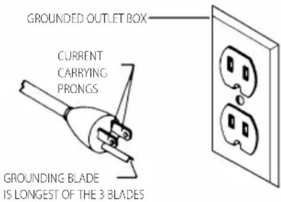
- This tool is intended for use on a circuit that has an outlet that looks like the one illustrated in Fig. B. The tool has a grounding plug that looks like the plug illustrated in Fig. B. A temporary adapter, which looks like the adapter illustrated in Fig. C, may be used to connect this plug to a 2-pole receptacle as shown in Fig B if a properly grounded outlet is not available. The temporary adapter should be used only until a properly grounded outlet can be installed by a qualified electrician. The green-colored rigid ear, lug, and the like, extending from the adapter must be connected to a permanent ground such as a properly grounded outlet box.
Fig. B
text_image
GROUNDED OUTLET BOX CURRENT CARRYING PRONGS GROUNDING BLADE IS LONGEST OF THE 3 BLADESFig. C
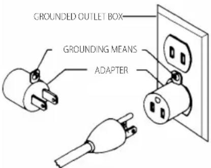
text_image
GROUNDED OUTLET BOX GROUNDING MEANS ADAPTERnOTE: In Canada, the use of a temporary adapter is not permitted by the Canadian Electric Code.
DANGER: In all cases, make certain that the receptacle in question is properly grounded. If you are not sure, have a qualified electrician check the receptacle.
EXTENSION CORDS
WARNING: Use proper extension cords. Make sure your extension cord is in good condition and is a
3-wire extension cord which has a 3-prong grounding type plug and matching receptacle which will accept the machine's plug. When using an extension cord, be sure to use one heavy enough to carry the current of the machine. An undersized cord will cause a drop in line voltage, resulting in loss of power and overheating. Minimum Gauge for Cord Sets shows the correct gauge to use depending on the cord length. If in doubt, use the next heavier gauge. The smaller the gauge number, the heavier the cord.
Minimum Gauge for Cord Sets
| Volts | Total Length of Cord in Feet (meters) | ||||
| 120 V 25 (7.6) | 50 (15.2) 100 (30.5) 150 (45.7) | ||||
| 240 V 50 (15.2) | 100 (30.5) 200 (61.0) 300 (91.4) | ||||
| Ampere Rating | American Wire Gauge | ||||
| More Than | Not More Than | ||||
| 0 6 18 | 16 16 14 | ||||
| 6 10 | 18 16 14 12 | ||||
| 10 12 | 16 16 14 12 | ||||
| 12 16 | 14 12 Not Recommended | ||||
The label on your tool may include the following symbols. The symbols and their definitions are as follows:
V....volts
Hz......hertz
min minutes
or DC.....direct current
Class I Construction (grounded)
.../min.....per minute
BPM.....beats per minute
ClassII Construction (double insulated)
n_0 .....no load speed n .....rated speed
earthing terminal
⚠️ ____ safety alert symbol
△......visible radiation
......wearrespiratory protection
weareye protection
O....wearhearing
protection
readall documentation
SAVE THESE INSTRUCTIONS FOR FUTURE USE
Specifications
| Input 120V AC, 15 Amp |
| No-load speed 10000 RPM |
| Feed speed 14' (4.3 m) or 26' (7.9 m) per minute |
| Planing height Maximum 6" (152.4 mm)Minimum 1/8" (3.2 mm) |
Planing width Maximum 13" (325 mm)
Planing depth Maximum 1/8" (3.2 mm) (for boards 6" [152 mm] wide or less)
Electrical Connection
Be sure your power supply agrees with the nameplate marking. Volts, 50/60 Hz or "AC only" means your planer must be operated only with alternating current and never with direct current. Voltage decrease of more than 10% will cause loss of power and overheating. All DEWALT tools are factory tested, if this tool does not operate, check the power supply.
Intended Use
This planer is designed for professional wood working.
DO NOT use under wet conditions or in presence of flammable liquids or gases.
DO NOT let children come into contact with the tool. Supervision is required when inexperienced operators use this tool.
Fan-Assisted Chip Ejection System
Your planer is equipped with a fan-assisted chip ejection system to aid in exhausting chips from the unit. The fan-assisted chip ejection system will work in conjunction with independent dust collection systems.
NOTE: It is not recommended that a shop vac be connected to the DW735. The capacity of most vacs does not support the volume of chips ejected during planing. The vacuum hose may clog stopping the flow of chips. It is recommended to use the dust collection system to clean debris from the interior of the tool.
See the Troubleshooting Guide, for additional information.
Automatic Carriage Lock
There is no manual carriage lock on your planer. A device that automatically minimizes the movement that causes snipe during planing is designed into the four threaded posts.
ASSEMBLY AND ADJUSTMENTS
WARNING: Do not remove guards (7, Fig. D). Several injury could result.
Fig. D
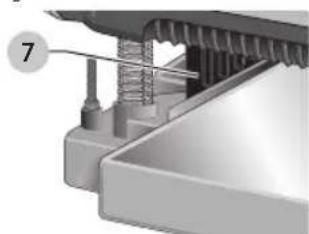
natural_image
Mechanical assembly diagram showing a threaded component inserted into a housing (no text or symbols visible)WARNING: To reduce the risk of serious personal injury, turn tool off and disconnect tool from power source before making any adjustments or removing/installing attachments or accessories. An accidental start-up can cause injury.
English
Transporting the Planer (Fig. A)
WARNING: For your own safety, it is recommended that two people carry this machine or serious injury could result.
When moving your planer, carry it either by the side carrying handles 2 or by the handles 3 at the base of the planer.
Bench Mounting (Fig. A)
To facilitate bench mounting, two different sized holes 4 are provided on the four corners of your planer. If mounting the planer with bolts, use the larger holes. If mounting the planer with nails or screws, use the smaller holes. It is not necessary to use both sets of holes.
Always mount your planer firmly to prevent movement. To enhance the tool's portability, it can be mounted to a piece of 1/2" (12.7 mm) or thicker plywood which can then be clamped to your work support or moved to other job sites and reclamped.
NOTE: If you elect to mount your planer onto a piece of plywood, make sure that the mounting screws don't protrude from the bottom of the wood. The plywood must sit flush on the work support.
CAUTION: The mounting surface should not be wrapped or otherwise uneven.
To Attach the Depth Adjustment Crank Handle (Fig. E)
- Remove the screw located in the crank handle shaft.
- Insert the crank handle 5 over the shaft.
- Secure in place with the screw and T-wrench 8 provided.
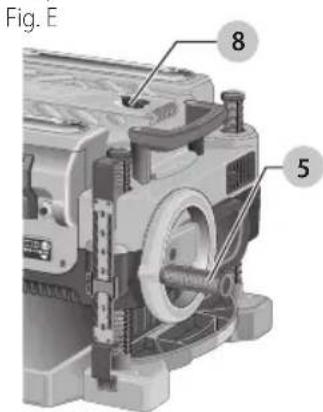
text_image
Fig. E 8 5Dust Ejection Ports (Fig. F)
Your planer comes with a dust ejection port. The round port 9 as shown in Figure. F is for use with a 4" (100 mm) dust collector hose.
To Set Up Dust Ejection (Fig. F)
WARNING: Do not operate your planer without the dust ejection port locked into place. Do not insert anything into the dust ejection chute unless the planer is unplugged and you are clearing a clog or obstruction in the unit. Do not get your face or eyes near the dust ejection port
when the planer is in operation. Serious injury could result.
WARNING: Chips are ejected at significant velocity. Keep hands and face clear of dust ejection port.
- Select the port 9.
- Depress the lock button 11 on the chip ejection chute 10.
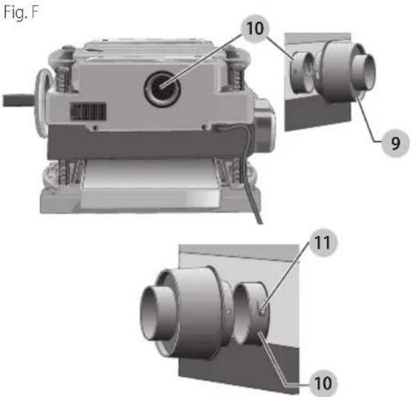
text_image
Fig. F 10 9 11 10-
Slide the notches in the dust port over the pins on the chip ejection chute.
-
Rotate the port until the button engages the dust ejection chute and locks in place.
To Remove the Dust Ejection Port (Fig. F)
- Use the T-wrench to depress the lock button 11 on the dust chute.
- Twist the port until the pins are disengaged from the notches on the port.
- Pull the dust ejection port off of the dust chute.
Depth Adjustment (Fig. G)
Depth Adjustment Scale (Fig. G)
The depth adjustment scale 14, located on the right front of your planer, indicates the finished thickness of your workpiece. One rotation of the depth adjustment crank is equal to 1/16" (1.6 mm), half rotation is equal to 1/32" (0.8 mm), etc.
Fig. G
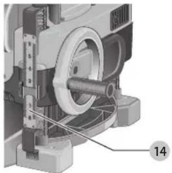
natural_image
Mechanical assembly diagram showing a motor with gears and shafts, labeled with number 14 (no text or symbols beyond label)Depth Adjustment Crank
Turning the crank clockwise lowers the cutterhead. Turning the crank counterclockwise raises the cutterhead.
Turret Stop (Fig. H)
Your planer is equipped with a turret stop 17 for planing multiple boards to the same pre-set depth. Stops are set at 1/8" (3 mm), 1/4" (6.5 mm), 1/2" (12.7 mm), 3/4" (19 mm), 1" (25.5 mm), and 1–1/4" (32 mm).
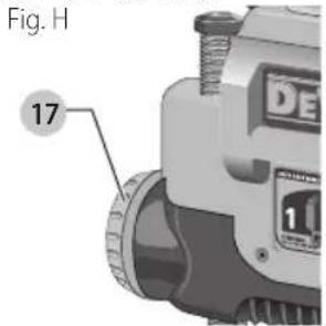
text_image
Fig. H 17To Set the Minimum Depth to Which the Carriage can Travel with the Turret Stop
- Be sure the carriage is set above 1–1/4" (32 mm) before trying to set the turret stop.
- Turn the dial on the front left of the planer until the desired thickness setting aligns with the red indicator, then lower the carriage.
- Plane the workpiece at desired increments until the correct final thickness is achieved.
NOTE: Do not use force to crank the carriage below the level that the turret stop indicates. Permanent damage to the height adjust ment system on your planer will result.
OPERATION
WARNING: To reduce the risk of serious personal injury, turn unit off and disconnect it from power source before making any adjustments or removing/installing attachments or accessories. An accidental start-up can cause injury.
On/Off Switch (Fig. I)
To turn the planer on, lift the switch 12 up. The planer locks on automatically. To turn the tool off, press the switch down. A hole 13 is provided under the switch for insertion of a padlock to lock off the planer.
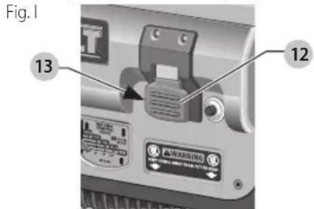
text_image
Fig.1 13 12Speed Selection (Fig. J)
NOTE: Only switch speeds when the planer is running.
Your planer has the ability to feed material at two different speeds. The two-speed feature 16 was designed to improve efficiency when planing and to provide the best possible surface finish to a variety of materials.
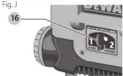
text_image
Fig. J 16 1 2To remove material thickness more quickly, set the unit at speed "2". This setting delivers 96 cuts per inch to the material.
For finishing, set the unit to speed "1". Speed "1" is ideal for ensuring the finest finish on the last pass before your final thickness is achieved.
NOTE: When planing particularly hard or figured species of wood, speed "1" is recommended. The slower feed rate will reduce knife wear and tear-out by delivering 179 cuts per inch to the material.
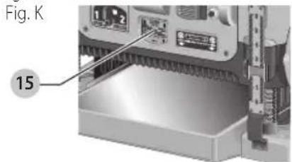
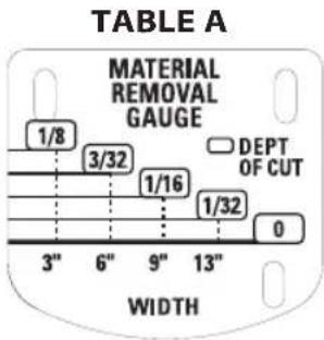
Material Removal Gauge (Fig. K)
Your planer is equipped with a material removal gauge 15. It is used to indicate the amount of wood that will be removed in one pass with the carriage set at its current height.
text_image
Fig. K 15To Use the Material Removal Gauge
- Slide approximately 3" (75 mm) of your material under the middle of the carriage.
- Be sure the wood is lying flat against the base of the planer. If the material is inserted at an angle, the reading may be inaccurate.
- Crank the carriage down on the material until the material removal bar engages the wood. You will see the red arrow begin to move up the scale indicating the amount of material to be removed with the carriage at that height.
- Adjust the carriage height until the desired depth of cut appears on the gauge.
- Pull the material out from under the carriage.
- Turn the unit on and feed your material into the cutterhead.
NOTE: Do not exceed the recommended depth of cut for various widths of material recommended on the material removal gauge.
ENGLISH
WARNING: DO NOT switch the unit on with the historical positioned under the carriage. Serious injury could result.
Planing Basics
Proper Planing Technique
WARNING: DO NOT turn the unit on with the material already inserted under the carriage. Wait until the rollers and cutterhead are up to full speed before feeding your material into the machine.
To Plane Your Material
- Lower the carriage to the desired height for your first pass.
- Turn the unit on and feed the material into the feed rollers.
- Examine the finished cut and adjust the carriage to the appropriate height for your next pass.
NOTE: Flip the board back and forth between each pass.
See the Troubleshooting Guide, for additional information. For best results, plane both sides of the workpiece to reach a desired thickness. For example, if you need to remove 1/8" (3 mm) from your workpiece, remove 1/16" (1.6 mm) from each side. This not only allows the workpiece to dry with an even moisture content, it also produces finer cuts.
WARNING: Plane only wood that is free from foreign objects, with no loose knots and as few tight knots as possible. Do not plane wood that is severely warped, twisted, knotted or bowed.
WARNING: Do not place your body between the rear of a planer and a stationary object while material is feeding. Serious injury could result.
Minimum/Maximum Width/Height/Depth
NOTE: Always plane in the direction of the grain. Support the workpiece adequately at all times. Planing material less than 3/4" (19 mm) wide is not recommended. If you must plane narrow material, group several pieces together and plane them as one wide workpiece whenever possible. The maximum depth of cut your planer can take in one pass is 1/8" (3 mm) [on material less than 6" (152 mm) wide]. Never attempt to modify your planer to take a deeper cut. Follow the recommended depth/width of cut guidelines shown in Table A for best results.
text_image
TABLE A MATERIAL REMOVAL GAUGE DEPT OF CUT 3" 6" 9" 13" WIDTH 1/8 3/32 1/16 1/32 0Snipe
Snipe is a depression made when an unsupported end of your material drops toward the floor, causing the opposite end to lift up into the cutterhead.
To Avoid Snipe
Feed the workpiece into the planer so it is level and remains flat against the base at all times.
Keep the workpiece level throughout planing operation by receiving or "catching" it from the rear of the planer.
If you are planing material that is especially long, the use of additional material support is recommended.
Twisted, Cupped and Bowed Wood (Fig. L)
If both sides of your material are very rough or if the material is cupped, bowed or twisted, your planer may not produce the desired result. Ideally, you should have at least one level face/surface on your material before you plane. Your thickness planer will work best with material that has been run through a jointer to produce one flat surface. If you do not have at least one flat surface or a jointer, see the following recommendations.
Fig. L
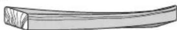
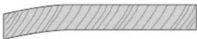
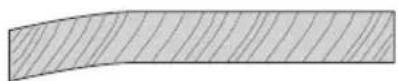
To Plane Twisted Wood (Fig. M)
WARNING: Twisted wood may jam your thickness planer. If a jam occurs, turn the power off, disconnect the power supply and raise the carriage to release the material from the cutterhead.
If your material is only slightly twisted:
Plane both sides alternating from one to the other until the desired thickness is reached.
Fig. M
natural_image
Illustration of a wooden plank with visible grain patterns (no text or symbols)To Plane Cupped Wood (Fig. N)
To obtain the best possible results with cupped wood: Rip the material down the middle and plane it as two separate pieces.
Ripping the material reduces the severity of the cup and allows the machine to deliver better results. Understand that you will have to remove more material on cupped wood to achieve the desired thickness than you would on a normal board.
If Ripping the Material is Not an Option
Plane one side of the material until flat, then plane the opposite side until it is also flat.
NOTE: Do not flip the board back and forth between each pass if wood is cupped.
Fig. N
TOP FIAT
BOTTOM FIAT
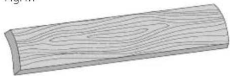
To Plane Bowed Wood (Fig. O)
The feed rollers and cutterhead in your planer will push the bow out of the material as it feeds. However, when the material exits the planer, the pressure of the rollers and cutterhead will release allowing the wood to spring back into a bowed formation. To properly remove the bow, use a jointer.
Fig. 0
BOWED WOOD Will BE FIATTENED BY FEED ROILERS AnD CUTTERhEAD...
...BUT BOW Will RETURn AFTER WOOD is PIAnED
MAINTENANCE
WARNING: To reduce the risk of serious personal injury, turn unit off and disconnect it from power source before making any adjustments or removing/installing attachments or accessories.
An accidental start-up can cause injury.
Periodic Maintenance
- Routinely check the tool for damage or broken parts.
- Clean the top cover, dust shroud and all accessible areas of the unit of dust and wood debris that have collected in from planeing.
- Wipe off infeed and outfeed rollers.
- Clean base table. Light waxing will help wood material pass through the planer.
- Evaluate blade sharpness condition. Replace as necessary.
- Gauge Calibration, check thickness gauge calibration and turret stop calibration.
- Check brushes for wear and replace as necessary.
Changing or Rotating the Planer Knives
WARNING: To reduce the risk of serious personal injury, disconnect the planer from the power source before attempting to change or access the knives. An accidental start-up can cause injury.
To Change Planer Knives (Fig. P-U)
-
Use the T-wrench to remove the four screws in the top of the planer.
-
Lift the top off (Fig. P) and place it aside. Fig. P
-
Remove the three wing nuts that seal the dust shroud over the cutterhead.
-
Rotate the dust shroud up so the round connection that locks onto the fan housing is in the open position (Fig. Q).
Fig. Q -
Push the dust shroud to the left so it disengages from the fan housing.
-
Take the dust shroud out of the unit (Fig. R) and set it aside.
Fig. R -
The cutterhead is now exposed. If the eight screws in the cutterhead clamp are not visible, use a piece of scrap wood to carefully rotate the cutterhead (Fig. S) until the screws are accessible and the cutterhead lock lever 18 engages. This will prevent further rotation of the cutterhead as you change the knives.
English
Fig. S
18
WARNING: Keep your fingers away from the head at all times. Use the tool provided to handle the knives.
- Use the T-wrench to remove the eight screws on the knife clamp and set them in the small screws bin 19 on the front panel of the planer (Fig. T). Fig. T
19
- Use the magnets on the top of the T-wrench to attract the knife clamp and lift it off of the cutterhead. One of the knives should now be exposed.
- Use the magnet 20 on the top of the T-wrench (Fig. S) to attract the knife. Avoid touching it with your fingers.
NOTE: Before installing the knife, ensure the cutterhead and knife are free of debris, clean if needed.
Fig. U
20
If Only One Side of the Knife Is Worn
- Rotate the knife around so that the sharp, unused edge hangs over the end of the cutterhead where it will cut the material. Be sure to set the oblong holes in the knife over the pins machined on the cutterhead.
- Reset the knife clamp over the knife. Be sure to align the beveled edge on the clamp with the sharp, cutting edge of the knife. If these are not aligned correctly, the clamp will not secure the knife properly.
- Install the screws into the clamp and tighten sufficiently. NOTE: Make sure all screws are tightened sufficiently.
To Access the Other Two Knives
- Depress the cutterhead lock lever 18 as shown in Figure S.
- Use the piece of scrap wood to carefully turn the cutterhead until it locks into place revealing another knife clamp.
- Follow the same knife change procedure indicated above.
- Repeat the procedure for the last dull knife.
After Installing New Knives
- Insert the round end of the dust shroud into the fan housing and rotate it down to lock it into place.
- Place the three wing nuts back into the shroud.
- Screw the top cover of the planer back onto the unit.
nOTE: The planer will not operate if the top cover is not placed correctly.
Brush Change (Fig. V, W)
Your planer is equipped with brush caps 21 that are external to the motor. If your brushes need to be replaced, begin by acquiring a new set from a DEWALT service center or a dealer authorized to service DEWALT products. Use only identical DEWALT brushes.
Fig. V
21
To Replace the Brushes on your Planer (Fig. V, W)
- Use the T-wrench to remove the top cover and brush cover screen on the planer.
- Use a flathead screwdriver to unscrew the brush cap located in the right, rear of the unit 22. Fig. W
22
- Do the same for the brush cap located on the side of the motor, inside the planer cover.
- Place the new brushes into the brush holders.
English
- After installing the brushes, replace the top cover and brush cover screen.
- Before using the planer, run the unit for 10 minutes to seat new brushes.
nOTE: If existing brushes do not need replacing, be sure to maintain the same orientation when you reinstall them.
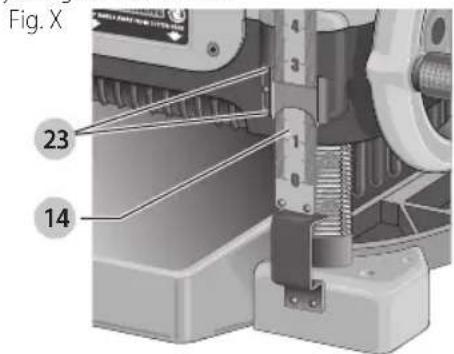
Calibrating the Depth Adjustment Scale (Fig. X)
The depth adjustment scale 14 on your planer is set at the factory. However, with extended use, the depth adjustment scale could show an incorrect measurement.
To check the depth adjustment scale, plane a piece of scrap wood, noting the measurement on the depth adjustment scale.
Measure the finished thickness of the workpiece. If the thickness of the workpiece does not match the reading on the depth adjustment scale, loosen the two screws 23 on the red indicator. Adjust the pointer up or down until its reading matches the finished thickness of the workpiece. Securely re-tighten the screws.
text_image
Fig. X 23 14Base Maintenance
Keep the table clean and free from oil, grease, and pitch. Treat the table with paste wax to help maintain its smooth finish.
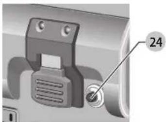
Circuit Breaker Reset Button (Fig. Y)
Your planer is equipped with an 18 amp circuit breaker. If your planer becomes overloaded and stops operating, turn off the planer, let the unit sit for 2 minutes and press the reset button 24 before you resume working.
Fig. Y
natural_image
Close-up of a mechanical component with a labeled pin (24) and a circular annotation (no readable text or symbols beyond the number)WARNING: To prevent the planer from starting unexpectedly if power is interrupted by a circuit breaker trip, make sure the switch is in the OFF position before restoring power.
nOTE: Circuit breaker overload is often the result of dull knives. Change your knives on a regular basis to avoid
tripping your breaker. Check your knives before re-setting the circuit breaker and continuing to plane.
See the Troubleshooting Guide for additional information on circuit breaker trips.
Replacing the Drive Belt
Drive belts are available at extra cost at DEWALT authorized service centers. Replacement of the drive belt should be performed by qualified service personnel.
Chip Ejection Fan (Fig. P–R, Z)
The chip ejection fan on your planer should be cleaned or cleared of debris periodically.
Fig. Z

natural_image
3D rendering of a mechanical component with a cylindrical housing and a separate cylindrical part (no text or symbols visible)WARNING: Turn off and unplug the planer prior to charging the chip ejection fan.
To Access the Fan
- Remove the top cover of the planer with the T-wrench.
- Remove the dust shroud (Fig. P-R) and place it aside.
- Remove the screws and clips around the fan housing.
- Remove the fan housing and place it aside as shown. The fan will now be exposed for cleaning.
See the Troubleshooting Guide for additional information.
WARNING: Be sure to properly attach the fan housing and assemble the shroud and top cover correctly before using your planer again.
Cleaning
WARNING: Blow dirt and dust out of all air vents with clean, dry air at least once a week. To minimize the risk of eye injury, always wear ANSI Z87.1 approved eye protection when performing this procedure.
WARNING: Never use solvents or other harsh chemicals for cleaning the non-metallic parts of the tool. These chemicals may weaken the plastic materials used in these parts. Use a cloth dampened only with water and mild soap. Never let any liquid get inside the tool; never immerse any part of the tool into a liquid.
It is recommended that, once a year, you take or send the tool to a DEWALT certified service center for a thorough cleaning, inspection and lubrication of the gear case.
Accessories
WARNING: Since accessories, other than those offered by DEWALT, have not been tested with this product, use of such accessories with this tool could be hazardous. To reduce the risk of injury, only DEWALT recommended accessories should be used with this product.
English
Recommended accessories for use with your tool are available at extra cost from your local dealer or authorized service center. If you need assistance in locating any accessory, please contact DEWALT Industrial Tool Co., 701 East Joppa Road, Towson, MD 21286, call 1-800-4-DEWALT (1-800-433-9258) or visit our website: www.dewalt.com.
Four accessories are available for the DW735
Thickness Planer.
- DW7350 Mobile Stand
- DW7351 Folding Tables
• DW7352 13" (325 mm) Knives
• DW7353 Chip Ejection Accessory
nOTE: Helical cutterheads have not been tested with this product and are not recommended for use.
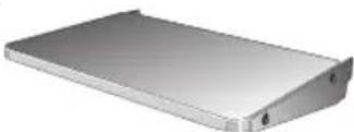
DW7351 Accessory Folding Tables (Fig. AA)
WARNING: For your own safety, read the tool instruction manual before attaching the tables.
Failure to heed these warnings may result in personal injury and serious damage to the planer and the accessory. When servicing this tool, use only identical replace ment parts. Have damaged cords replaced by an authorized service center.
Your DW7351 folding table box should include:
2 folding tables
4 nuts
4 cap screws
4 stepped bolts
4 springs
Fig. AA
natural_image
3D rendering of a metallic rectangular electronic device with a flat top and side edge (no text or symbols visible)Set-up and Installation of Base Hardware (Fig. BB-DD)
- Place planer on a secure table or workbench. Position planer so the front 3–4" (75–100 mm) of the base can be accessed from the underside.
- Secure the rear of the planer to the table/bench with nails or screws to prevent it from tilting or falling from the table.
WARNING: The planer could tilt or fall from the table it is not properly secured opposite the end where the folding table is being installed. Serious injury may result.
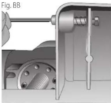
- Place the spring onto the small end of the stepped bolt.
- Insert the end of the bolt with the spring around it into the larger hole on the side of the base.
- Push the stepped bolt all the way through the hole in the first rib on the underside of the planer. The spring should engage the rib slightly and the threads should show on the right side of the rib.
- On the underside of the planer, use a wrench to hold the nut in place while turning the stepped bolt into it. The 5/32" (4 mm) hex wrench can be used to turn the stepped bolt until it is fully secured (Fig. BB).
natural_image
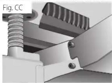
Mechanical assembly diagram showing a piston-cranked mechanism with internal components (no text or symbols)- Install the smaller screw into the lower threaded hole on the side of the base. Use the 5/32" (4mm) hex wrench to tighten that fastener securely (Fig. CC).
- Depress the top pin until it is flush with the base and slide the top hole of the table over the pin and release the pin so they lock together (Fig. CC, DD).
natural_image
Mechanical assembly diagram showing a threaded component inserted into a bracket (no text or symbols visible)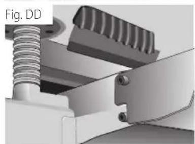
natural_image
Mechanical assembly diagram showing spring and lever components (no text or symbols)- To attach the table to the rear of the planer, install the bolts and spring following the above procedure.
Your tables should now fold up and down on the top screw and rest on the bottom screw while in position for planing.
NOTE: To transport the planer with the tables, fold them up and carry the unit as recommended by the planer manual.
WARNING: For your own safety, it is recommended that two people carry this machine or serious injury could result.
To Remove the Tables
- Depress the spring-loaded bolts on the base and slide each end of the table toward you so they disengage the holes in the tables. You may want to use the T-wrench from your planer to push the bolts flush with the base to easily remove the tables.
- Leave the hardware (stepped bolts and small cap screw) in the base until you need to re-attach the tables.
Repairs
WARNING: To assure product SAFETY and REQUENCY, rehabilitation, repairs, maintenance and adjustment (including brush inspection and replacement, when applicable) should be performed by a DEWALT factory service center or a DEWALT authorized service center. Always use identical replacement parts.
Register Online
Thank you for your purchase. Register your product now for:
- WARRAnTY sERViCE: Registering your product will help you obtain more efficient warranty service in case there is a problem with your product.
- COnFiRMATiOn OF OWnERshiP: In case of an insurance loss, such as fire, flood or theft, your registration of ownership will serve as your proof of purchase.
- FOR YOUR SAFETY: Registering your product will allow us to contact you in the unlikely event a safety notification is required under the Federal Consumer Safety Act.
Register online at www.dewalt.com/register.
Three Year Limited Warranty
DEWALT will repair, without charge, any defects due to faulty materials or workmanship for three years from the date of purchase. This warranty does not cover part failure due to normal wear or tool abuse. For further detail of warranty coverage and warranty repair information, visit www.dewalt.com or call 1-800-4-DEWALT (1-800-433-9258). This warranty does not apply to accessories or damage caused where repairs have been made or attempted by others. THIS LIMITED WARRANTY IS GIVEN IN LIEU OF ALL OTHERS, INCLUDING THE IMPLIED WARRANTY OF MERCHANTABILITY AND FITNESS FOR A PARTICULAR PURPOSE, AND EXCLUDES ALL INCIDENTAL OR CONSEQUENTIAL DAMAGES. Some states do not allow limitations on how long an implied warranty lasts or the exclusion or limitation of incidental or consequential damages, so these limitations may not apply to you. This warranty gives you specific legal rights and you may have other rights which vary in certain states or provinces. In addition to the warranty, DEWALT tools are covered by our:
1 YEAR FREE sSERVICE
DEWALT will maintain the tool and replace worn parts caused by normal use, for free, any time during the first year after purchase.
90 DAY MOnEY BACK gUARAnTEE
If you are not completely satisfied with the performance of your DFWALT Power Tool, Laser, or Nailer for any reason, you can return it within 90 days from the date of purchase with a receipt for a full refund – no questions asked.
IATin AMERiCA: This warranty does not apply to products sold in Latin America. For products sold in Latin America, see country specific warranty information contained in
the packaging, call the local company or see website for warranty information.
FREE WARning IABEI REPIACEMENT: If your warning labels become illegible or are missing, call 1-800-4-DEWALT (1-800-433-9258) for a free replacement.
Troubleshooting Guide
| Problem Possible Cause Possible Solution | ||
| If the material does not feed properly | Check for dull knives. | Rotate or replace as necessary. Refer toChanging the Planer Knivessection. |
| Check for excess clogging in the dust shroud. | Refer toPeriodic Maintenanceand Figures P–R in theChanging or Rotating the Planer Knivessection. | |
| Check for excess oil/debris/pitch on feed rollers. | Refer toPeriodic MaintenanceandCleaningparagraphs under theMaintenancesection. | |
| Check for excessively twisted, cupped or bowed material. | Refer toTwisted,Cupped and Bowed Woodparagraph in theBasic Planingsection. | |
| Check for a broken drive belt. Refer toReplacing the Drive Beltparagraph in theMaintenancesection. | ||
| If the circuit breaker trips repeatedly Dull knives Dull knives can cause motor overloading, rotate or replace as necessary. Refer toChanging the Planer Knivessection.NOTE:Circuit breaker overload is often the result of dull knives. If the circuit breaker on your planer trips, check the sharpness of your knives before attempting to reset the breaker in order to continue planing. | ||
fabrication classe II (double isolation)
natural_image
Mechanical assembly diagram showing a threaded component inserted into a housing (no text or symbols visible)natural_image
Mechanical assembly diagram showing a motor with gears and shafts, labeled with number 14 (no text or symbols beyond label)text_image
MATERIAL REMOVAL GAUGE 1/8 3/32 1/16 1/32 0 DEPT OF CUT 3" 6" 9" 13" WIDTHArrondi
natural_image
Illustration of a wooden plank with visible grain patterns (no text or symbols)natural_image
Simple diagram showing three spheres on a hatched surface (no text or symbols)MAis IA CAMBRURE RÉAPPARAÏT APRÈs IE RABOTAgE DE IA PIAnChE
MAINTENANCE
WARNING: To reduce the risk of serious personal injury, turn unit off and disconnect it from power source before making any adjustments or removing/installing attachments or accessories.
An accidental start-up can cause injury.
FRAnÇAis
natural_image
Mechanical assembly diagram showing a motor or clamp mechanism with two upward arrows indicating motion direction (no text or symbols present)natural_image
3D mechanical assembly diagram showing internal components and housing (no text or symbols)natural_image
3D mechanical assembly diagram showing a component with arrows indicating motion or force direction (no text or symbols)natural_image
Close-up of a hand using a tool to cut a metallic cylindrical component (no text or symbols visible)natural_image
Mechanical assembly diagram showing a component with labeled parts (Fig. T and 19), no readable text or symbols beyond labels.natural_image
Close-up of a hand using a tool to cut or mark a mechanical component, labeled 'Fig. U' with number 20 (no text or symbols on the diagram itself)natural_image
Close-up of a mechanical component with a numbered annotation (24) pointing to a button or knob (no readable text or symbols beyond the number)natural_image
3D rendering of a mechanical component with a cylindrical housing and a separate circular component (no text or symbols visible)natural_image
3D rendering of a metallic rectangular electronic component with a flat top and side connectors (no text or symbols visible)natural_image
Mechanical assembly diagram showing a shaft, housing, and internal components (no text or symbols)natural_image
Mechanical assembly diagram showing spring and gear components (no text or symbols)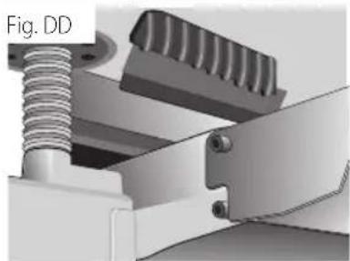
natural_image
Mechanical assembly diagram showing a spring-loaded component with threaded shaft and mounting bracket (no text or symbols)FRAnÇAis
natural_image
Mechanical assembly diagram showing a spring-loaded component with a numbered label (7), no readable text or symbols present.natural_image
Mechanical assembly diagram showing a motor and gear mechanism (no text or symbols)text_image
MATERIAL REMOVAL GAUGE 1/8 3/32 1/16 1/32 0 DEPT OF CUT WIDTH 3" 6" 9" 13"Tirón
natural_image
Illustration of a wooden plank with visible grain patterns (no text or symbols)Para cepillar madera abombada (Fig. N)
natural_image
Simple diagram showing three spheres on a hatched surface (no text or symbols)...PERO LA PANDEADURA VOLVERÁ DESPUÉS DE QUE SE CEPILLE LA MADERA
MANTENIMIENTO
natural_image
Mechanical assembly diagram showing a motor or gear mechanism with mounting flanges and a pulley (no text or symbols)natural_image
3D mechanical assembly diagram showing internal components and housing (no text or symbols)natural_image
3D mechanical assembly diagram showing a component with arrows indicating motion or force direction (no text or symbols)natural_image
Close-up of a hand using a tool to cut a metallic cylindrical component (no text or symbols visible)natural_image
Mechanical assembly diagram showing a component with labeled parts (Fig. T and 19), no readable text or symbols beyond labels.natural_image
Mechanical assembly diagram showing a hand operating a motor with a labeled component (no text or symbols present)natural_image
Close-up of a mechanical component with a numbered annotation (24) pointing to a button or knob (no readable text or symbols beyond the number)natural_image
3D rendering of a mechanical component with a cylindrical housing and two separate parts (no text or symbols visible)natural_image
Metallic rectangular electronic device with a flat top and side connectors (no visible text or symbols)natural_image
Mechanical assembly diagram showing internal components like gears and shafts (no text or labels)natural_image
Mechanical assembly diagram showing a threaded bolt and gear mechanism (no text or symbols)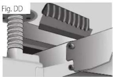
natural_image
Mechanical assembly diagram showing a threaded bolt and lever mechanism (no text or symbols)Eje Central Lázaro Cárdenas No. 18 - Local (55) 5588 9377 D, Col. Obrera
MERIDA, YUC
Calle 63 #459-A - Col. Centro (999) 928 5038
MONTERREY, N.L.
Av. Francisco I. Madero 831 Poniente - Col. (818) 375 23 13 Centro
PUEBLA, PUE
17 Norte #205 - Col. Centro (222) 246 3714
QUERETARO, QRO
Av. San Roque 274 - Col. San Gregorio (442) 2 17 63 14
SAN LUIS POTOSI, SLP
DEWALT Industrial Tool Co., 701 East Joppa Road, Towson, MD 21286
(DEC18) Part No. N486408 DW735 Copyright © 2003, 2004, 2005, 2009, 2011, 2013, 2018 DEWALT
The following are trademarks for one or more DEWALT power tools: the yellow and black color scheme, the "D" shaped air intake grill, the array of pyramids on the handgrip, the kit box configuration, and the array of lozenge-shaped humps on the surface of the tool.