
BHCB93640B - Basket BEKO - Free user manual and instructions
Find the device manual for free BHCB93640B BEKO in PDF.
| Product Type | Kitchen hood |
| Brand | Beko |
| Model | BHCB93640B / BHCB93640BH |
| Power supply | 220-240 V ~ 50 Hz |
| Motor power | 210 W |
| Lighting power | 2 x 3 W (LED) |
| Maximum air flow | 645 m³/h |
| Number of speeds | 3 speeds |
| Automatic shut-off function | Yes (15-minute timer) |
| Grease filter type | Washable aluminum filter (at least once a month) |
| Charcoal filter type | Activated charcoal filter (replace every 3 months) |
| Minimum distance from cooking surface | 65 cm |
| Exhaust duct diameter | 120 or 150 mm |
| Exhaust mode | Extraction or recirculation (with charcoal filter) |
| Bulb type | LED spot 3 W, GZ10 base |
| Motor insulation class | Class F |
| Electrical insulation class | Class I |
| Dimensions (approx.) | 90 cm width (90 cm model) |
| Weight | Not specified in the manual |
| Warranty | According to manufacturer's conditions |
Frequently Asked Questions - BHCB93640B BEKO
User questions about BHCB93640B BEKO
0 question about this device. Answer the ones you know or ask your own.
Ask a new question about this device
Download the instructions for your Basket in PDF format for free! Find your manual BHCB93640B - BEKO and take your electronic device back in hand. On this page are published all the documents necessary for the use of your device. BHCB93640B by BEKO.
USER MANUAL BHCB93640B BEKO
natural_image
Simple line drawing of a chimney emitting steam (no text or symbols)BHCB 93640 B - BHCB 93640 BH
EN - DE - ES - RO - FR - NL- KA- PT - SQ - CS - SK - PL - BG - BS - RU - KK
CONTENTS
| ENGLISH | 3-16 |
| DEUTSCH | 17-33 |
| ESPAÑOL | 34-50 |
| ROMÂNĂ | 51-66 |
| FRANÇAIS 67-82 | |
| NEDERLANDS 83-97 | |
| KARTULI 98-117 | |
| PORTUGUÊS 118-134 | |
| SHQIPTARE 135-149 | |
| ČESKY 150-164 | |
| SLOVENSKÝ 165-179 | |
| POLSKI 180-197 | |
| БЪЛГАРСКИ 198-216 | |
| BOSANSKI 217-230 | |
| РУССКИЙ | 231-251 |
| КАЗАКН | 251-271 |
Please read this user manual first!
Dear Valued Customer,
Thank you for preferring this Beko appliance. We hope that you get the best results from your appliance which has been manufactured with high quality and state-of-the-art technology. For this reason, please read this entire user manual and all other accompanying documents carefully before using the appliance and keep it as a reference for future use. If you handover the appliance to someone else, give the user manual as well. Follow the instructions by paying attention to all the information and warnings in the user manual.
Remember that this user manual may also apply to other models. Differences between models are explicitly described in the manual.
Meanings of the Symbols
Following symbols are used in various sections of this user manual:

Important information and useful hints about usage.

WARNING: Warnings against dangerous situations concerning the security of life and property.
WARNING: Warning for danger of fire.
WARNING: Warning for electric shock.
1 Important safety and environmental instructions
1.1 General safety
Important Safety Instructions Read Carefully And Keep For Future Reference This section contains safety instructions that will help protect from risk of fire, electric shock, exposure to leak microwave energy, personal injury or property damage. Failure to follow these instructions shall void any warranty.
- Beko products comply with the applicable safety standards; therefore, in case of any damage on the appliance or power cable, it should be repaired or replaced by the dealer, service center or a specialist and authorized service alike to avoid any danger. Faulty or unqualified repair work may be dangerous and cause risk to the user.
- This appliance is intended to be used in household and similar applications such as:
- Staff kitchen areas in shops, offices and other working environments;
- Farm houses
- By clients in hotels, and other residential type environments; - Bed and Breakfast type environments.
- Operate the appliance for its intended purpose only as described in this manual.
- The manufacturer cannot be held liable for damages resulting from improper installation or misuse of the product.
- This appliance can be used by children aged from 8 years and above and persons with reduced physical, sensory or mental capabilities or lack of experience and knowledge if they have been given supervision or instruction concerning use of the appliance in a safe way and understand the hazards involved.
- Children shall not be allowed play with the appliance. Cleaning and user maintenance shall not be made by children without supervision.
1 Important safety and environmental instructions
- The minimum distance between the supporting surface for the cooking vessels on the hob and the lowest part of your product must be at least 65 cm.
- If the instructions for installation for the gas hob specify a greater distance, this has to be taken into account.
- Make sure that your mains power supply complies with the information supplied on the rating plate of the appliance.
- Never use the appliance if the power cable or the appliance itself is damaged.
- Prevent damage to the power cable by not squeezing, bending, or rubbing it on sharp edges. Keep the power cable away from hot surfaces and naked flame.
- Use the appliance with a grounded outlet only.
WARNING: Do not connect the appliance to the mains until the installation is fully complete.
- Place the appliance in a way so that the plug is always accessible.
- Do not touch the lamps if they have operated for a long time. They can burn your hands since they will be hot.
- Follow the regulations set out by competent authorities on discharge of the exhaust air (this warning is not applicable for use without flue).
- Operate your appliance after putting a pot, pan etc. on the hob. Otherwise, high heat may cause deformation in some parts of your product.
- Turn off the hob before taking the pot, pan etc. from it. - Do not leave hot oil on the hob. Pans with hot oil may cause self combustion.
- Pay attention to your curtains and covers since oil may catch fire while cooking food such as fries.
- Grease filter must be cleaned at least monthly. Carbon filter must be replaced at least every 3 months.
1 Important safety and environmental instructions
- Product shall be cleaned accordance with user manual. If cleaning was not carried out in accordance with user manual, there may be fire risk.
- Do not use non-fire-resistant filtering materials instead of the current filter.
- Only use the original parts or parts recommended by the manufacturer.
- Do not operate the product without the filter and do not remove the filters while the product is running.
- In the event of be started any flame, de-energize your product and cooking appliances.
- In the event of be started any flame, cover the flame and never use water to extinguish.
- Unplug the appliance before each cleaning and when the appliance is not in use.
-
The negative pressure in the environment should not exceed 4 Pa (4x10 bar) while the hood for electric hob and appliances running on another type of energy but electricity operate simultaneously.
-
In the environment where the appliance is being used, the exhaust of devices running on fuel oil or gas, such as room heater must be absolutely isolated or device must be hermetical type.
- When connecting the flue, use pipes with a diameter of 120 or 150 ~mm . Pipe connection must be as short as possible and have as few elbows as possible.
- Danger of choking! Keep all the packaging materials away from children.
CAUTION: Accessible parts may become hot when used with cooking appliances.
- The product outlet must not be connected to air channels that include other smoke.
- The ventilation in the room may be insufficient when the hood for electric hob is used simultaneously with the devices operating on gas or other fuels (this may not apply to appliances that only discharge the air back into the room).
1 Important safety and environmental instructions
- Objects placed on the product may fall. Do not place any objects on the product.
- Do not flambe under the your product.
WARNING: Before installing the Hood, remove the protective films.
- Never leave high naked flames under the hood when it is in operation
- Deep fat fryers must be continuously monitored during use: overheated oil can burst into flames.
1.2 Compliance with the WEEE Directive and Disposing of the Waste Product:
This product complies with EU WEEE Directive (2012/19/EU). This product bears a classification symbol for waste electrical and electronic equipment (WEEE).
This symbol indicates that this product shall not be disposed with other household wastes at the end of its service life. Used device must be returned to official collection point for recycling of electrical and electronic devices. To find these collection systems please contact to your local authorities or retailer where the product was purchased. Each household performs important role in recovering and recycling of old appliance. Appropriate disposal of used appliance helps prevent potential negative consequences for the environment and human health.
1.3 Compliance with RoHS Directive
The product you have purchased complies with EU RoHS Directive (2011/65/EU). It does not contain harmful and prohibited materials specified in the Directive.
1.4 Package Information

Packaging materials of the product are manufactured from recyclable materials in accordance with our National Environment Regulations. Do not dispose of the packaging materials together with the domestic or other wastes. Take them to the packaging material collection points designated by the local authorities.
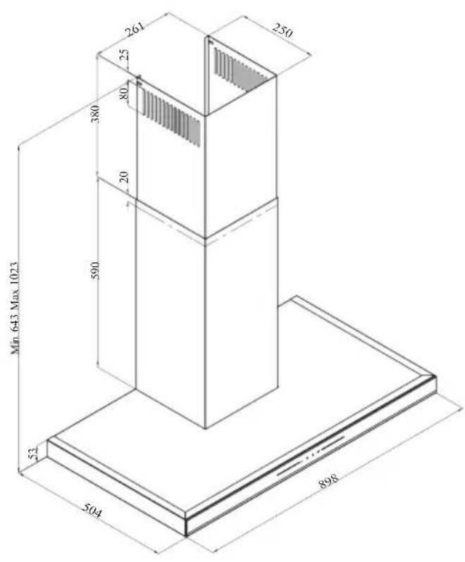
2 General appearance
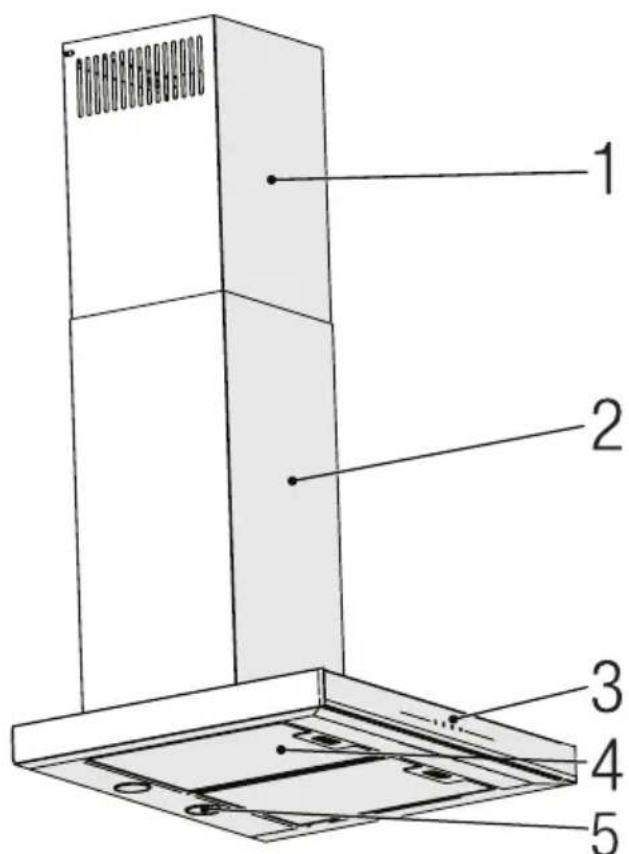
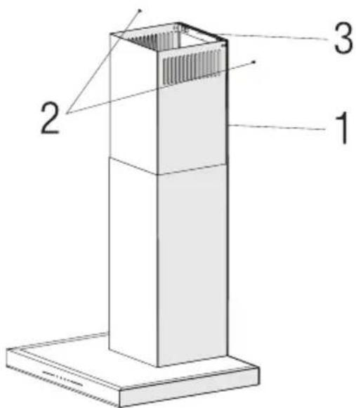
2.1 Overview
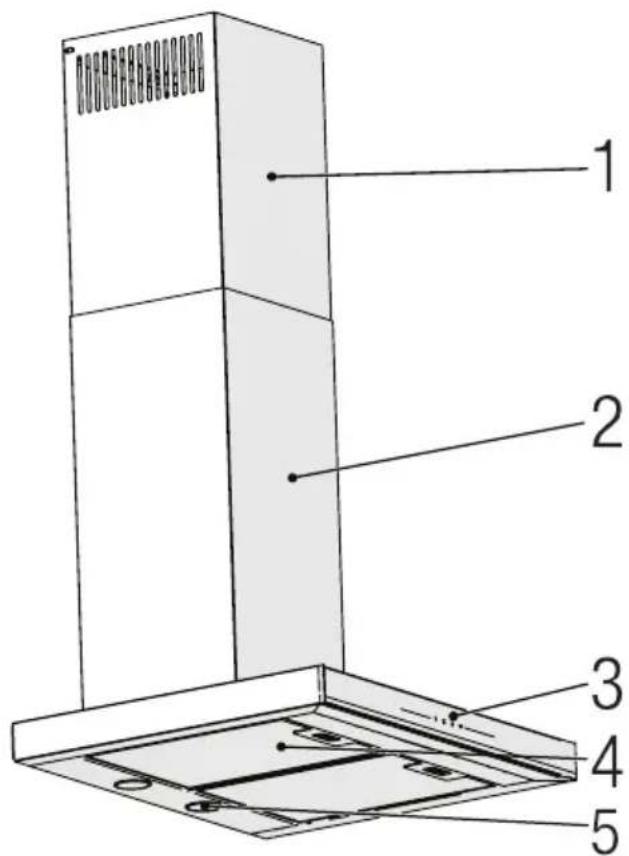
(Figure 1)

(Figure 2) BHCB 93640 B
BHCB 93640 BH
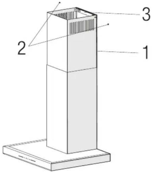
- Inner chimney
- Outer chimney
- Control panel
- Grease filter
- Lighting
2.2 Technical data
| Model BHCB 93640 B BHCB 93640 BH | |
| Supply voltage & Frequency 220-240V ~ 50 Hz | |
| Lamp power 2 x 3 W | |
| Motor power 210 W | |
| Flow rate – 3. Level 645 m3/h | |
| Insulation class of motor Class F | |
| Insulation class Class I | |
3 Operation of the appliance
3.1 Controlling the Appliance
 |  |  |  |
| KEY FUNCTION | |||
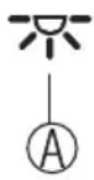
| A: Light On / Off | You may illuminate the cooking area by pressing this button. Re-press the button to turn off the lamp. | ||
| B: 1. Stage Button | Operates the appliance on 1st speed. When you press this button again to turn off the appliance, the screen speed stage turns off. | ||
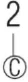
| C: 2. Stage Button | Operates the appliance on 2nd speed. When you press this button again to turn off the appliance, the screen speed stage turns off. | ||
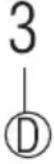
| D: 3rd Stage Button | Operates the appliance on 3rd speed. When you press this button again to turn off the appliance, the screen speed stage turns off. | ||
3.2 Energy efficient usage
- When using your appliance, adjust the speed settings according to vapour and odour intensity, in order to save energy.
- Use low speeds (1-2) under normal conditions, and high speed (3) for intense odour and vapour.
- The lamps on the hood are placed for illuminating the cooking area.
- Using them for environmental lighting shall cause unnecessary energy expenditure and insufficient lighting.
3.3 Operating the hood
- Your appliance contains a motor that has various speeds.
-
For better performance, we recommend using low speeds under normal conditions and high speeds in cases of strong odours and intense vapour.
-
You can start your appliance by pressing on the desired speed setting button. (B, C, D)
- You may illuminate the cooking area by pressing the lamp (A).
3.4 Automatic stop
Your appliance has Automatic Stop feature, enabling it to ventilate for a bit more and remove the unwanted odours and vapour inside the environment and turn off automatically after the cooking is done. To enable Automatic Stop feature, press the any speed stage button (B, C, D) on the control panel for longer than 2 seconds; the 15-minute timer function shall be activated. When the automatic stop feature is active, pressing the same speed button shall disable the automatic stop function and the appliance's motor shall stop. This feature is disables when you switch between different speed stages. If you want the appliance to stop automatically, you need to enable the automatic stop feature again.
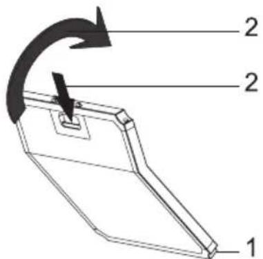
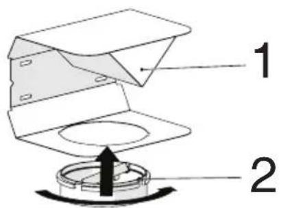
3.5 Replacement of Lamp
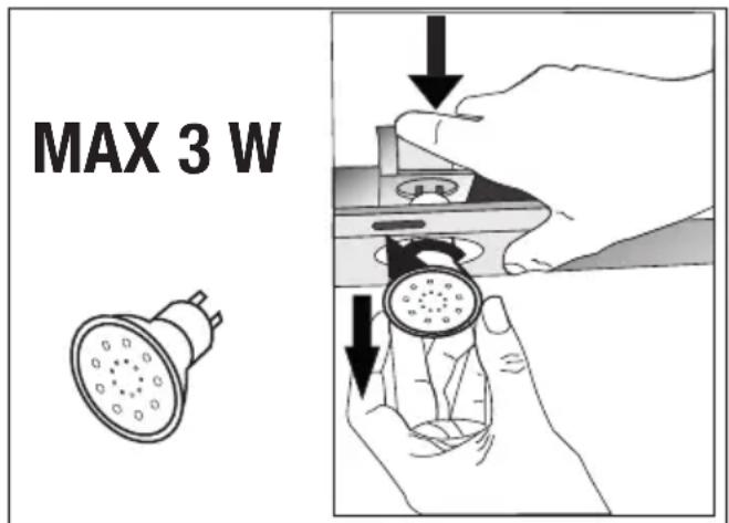
(Figure 3)
Make the electrical connections of the appliance. Your appliance uses 3W spot LED lamp. For replacing the lamps, push downwards on the holder from its behind, turn it counter-clockwise, and take it out downwards. Apply the above operation in re-
3 Operation of the appliance
verse to install new lamps (Figure 3).
| Bulb |  |
| Bulb Power 3 W | |
| Holder / Socket GZ 10 | |
| Bulb Voltage 220 - 240 V | |
| Size 53 x 50 mm | |
| ILCOS Code DR/F3-220-240-GZ10-50-53 | |
| Luminous flux 260 lm | |
| Correlated colour temperature | 3000 K |
This product contains a light source of energy efficiency class "F".
3.6 Operation with chimney connection
acted through the
flue duct, which is fastened to the connection head on the hood.
- The diameter of the flue duct must be the same as the connection ring. In horizontal settings, the pipe has to have a slight upward slope (around 10^ ) so that the air can exit the room easily.
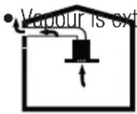
3.7 Operation without chimney connection
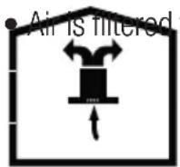
through the carbon
filter and recirculated in the room. Carbon filter is used when it is impossible to use a flue in the house.
- In flueless use, remove the flaps inside the flue adapter.
- Remove the aluminum grease filter. To install the carbon filter, fit the filter to the tabs by centring it on the plastic piece on both sides of the fan body. tighten it by turning right or left.
- Replace aluminum grease filter.
4 Clearing and maintenance

Before cleaning and maintenance, unplug the product or turn off the switch.
4.1 Cleaning of grease filter
Grease filter is used to retain the oil particles in the air. Grease filter may change colour after repeated cleaning. This is normal, and you do not have to replace your filters.
natural_image
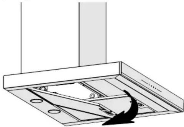
Technical line drawing of a ceiling structure with ventilation grilles and a downward arrow indicating airflow or movement (no text or symbols)(Figure 4)
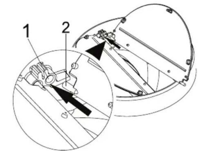
- Push the grease filter lock forward.
- Then pull it slightly down and pull it out (Figure 4). Otherwise, you may bend the filter. Wash and rinse grease filter with liquid detergent and replace grease filter to their seats by carrying out the steps specified above in reverse order. These grease filter are used to retain the oil particles in the air.

You may also wash the grease filter in the washing machine.

CAUTION: In case of normal use, clean your grease filter once in a month.
4.2 Replacement of Carbon Filters
(Figure 5)
- The appliance you have purchased is appropriate for use with carbon filters.
- Remove the grease filter (Figure 4).
- Place the lower part of the carbon filter to the motor cabinet (Figure 5).
- Press on the tab of the carbon filter and push it forward, and ensure that the tabs of carbon filter are engaged and locked. (Figure 5).
- Attach the grease filter.

CAUTION
- Carbon filter shall never be washed.
- Replace carbon filters once every 3 months.
- You can obtain the carbon filter from the authorized services.
5 installation of appliance

WARNING: Before starting the installation, read the safety information on User Manual.
WARNING: Failure to install with screws and stabilizers in accordance with these instructions may result in electric shock.
For the installation of the hood, please contact the nearest Authorized Service.
It is the customer's responsibility to prepare the location and electrical installation of the hood.
5.1 Position of the Appliance
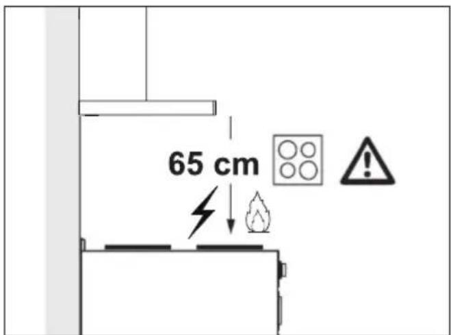
(Figure 6)
- Distance between the cooker and the cooker hood must be considered prior to assembly. This distance should be 65 cm (Figure 6).
- Distance must be measured from the surface of grate for gas cookers,
• from surface of glass for electric cookers.
5.2 Installation Accessories
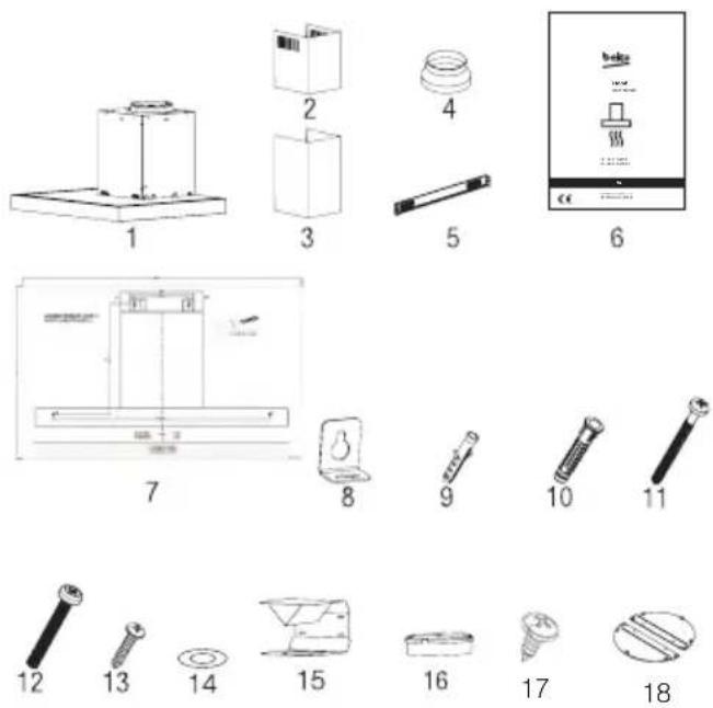
- Product
- Inner Chimney
- Outer Chimney
- ∅150/120 mm Plastic Flue Adapter
- Chimney Connection Plate
- User Manual
- Assembly Pattern
- 2x Hanging Plates
- 2x ∅6mm Plastic Dowel
- 4x ∅10mm Plastic Dowel
- 4x 5.5x60 Wall Mount Screw
- 2x M5x35 Hanging Plate Connection Screw
- 2x 3.9x22 Chimney Connection Plate Screw
- 2x M4 Washer
- Air Baffle
- Plastic Adapter (Air Diverter)
- 2x 3.5x9.5 Chimney Connection Plate Screw
- Chimney Clamp
The information required to make the location suitable for the installation of the hood is given below.
5 installation of appliance
5.3 Wall Mounting
- Wall must be flat, straight and have the sufficient bearing capacity.
- Depth of drilling holes must comply with the length of bolts.
- The bolts and dowels provided are suitable for brick walls. For other construction material (e.g. drywall, plate, porous concrete), suitable fixing dowels and nuts shall be used.
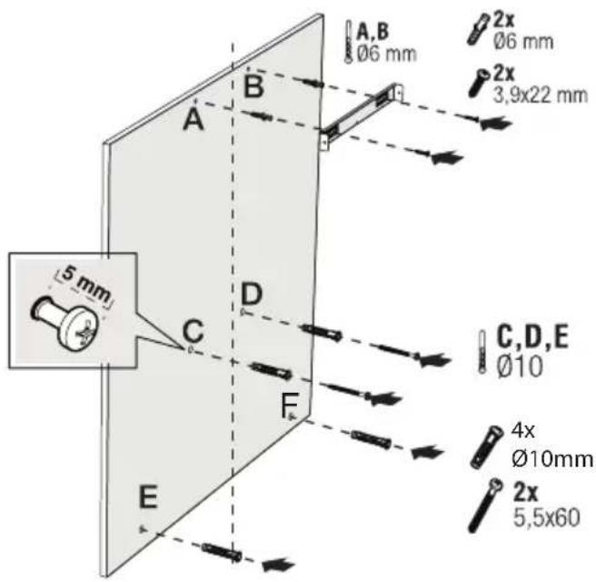
(Figure 7)

CAUTION: Before drilling, ensure that there are no power, gas or water pipes in the close proximity of the drilling locations.
Draw a mid location line from the ceiling perpendicular to the lower edge of the hood.
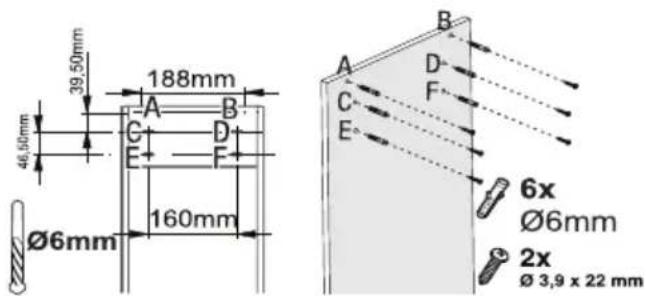
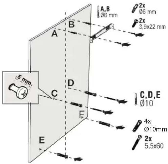
Fix the assembly scheme on the wall. For points A and B, take the maximum dimensions of the hood as reference, and drill points A and B you have marked with a ∅6mm drill bit, and tap ∅6mm plastic wall plugs. Install the chimney connection plate to the wall with 2 pieces of 3.9x22 screws (Figure 8).
To install the hood body, drill points C, D, E, F specified in the installation template with a ∅10mm drill bit and tap ∅10mm plastic dowels to these points (Figure 8).
Install 2 pieces of 5.5x60 mounting screws to points C and D with a clearance of 5 mm between the screw head and the wall (Figure 8).
(Figure 8)
Install two pieces of hanging plates to the body of the hood with M5x35 mounting screws (Figure 8).
natural_image
Technical line drawing of a mechanical assembly with a central component and base plate (no text or symbols)(Figure 9)
Hold the cooker hood by its body and place it on the mounting screws on the wall and tighten the screws (Figure 9).
Install M4 washers to the 5.5x60 suspension screws. Secure the cooker hood with a 5.5x60 screw to the wall through the mounting hole on
5 installation of appliance
the interior of the appliance (Figure 9).
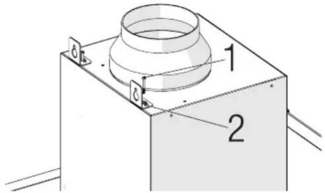
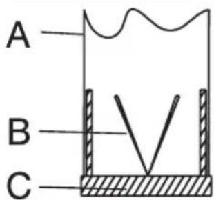
5.4 Connecting to Chimney
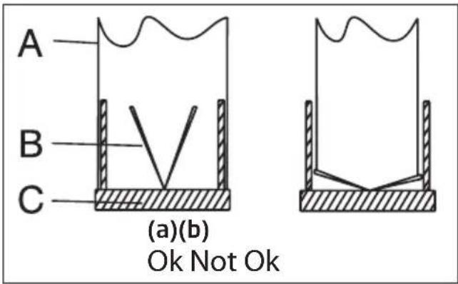
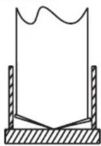
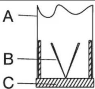
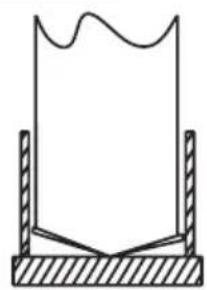
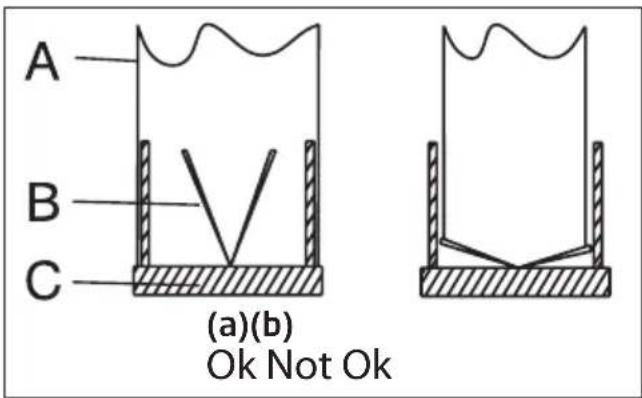
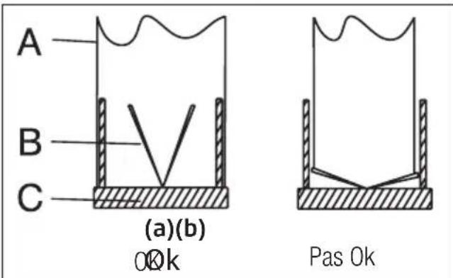
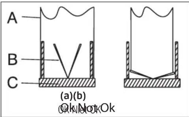
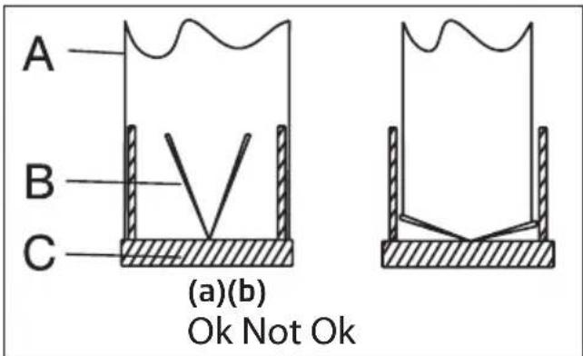
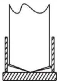
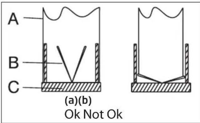
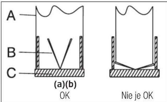
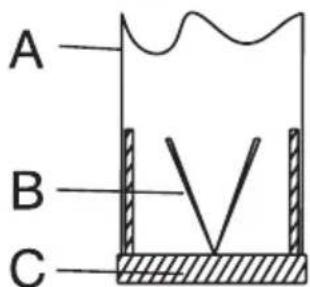
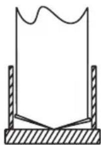
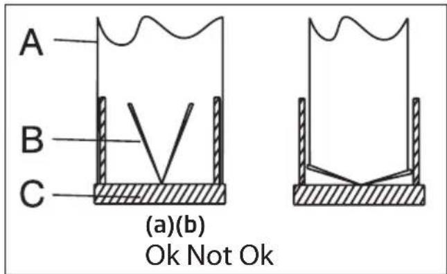
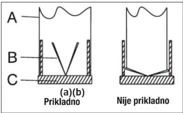
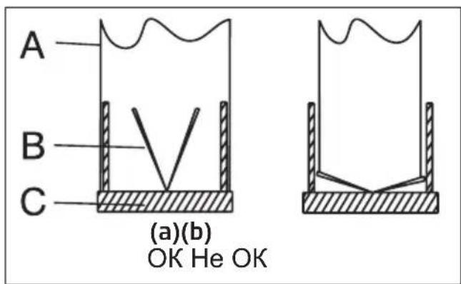
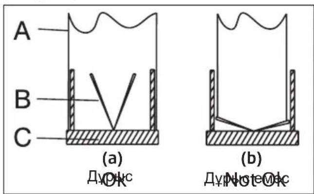
If you are going to use the ∅ 120/150 mm plastic Chimney adapter, connect one end of the pipe to this adapter, if you are not going to use it, to the direct output on the product. Connect the other end of the pipe to your Chimney. Check that these two connections are tight enough so they will not come out when the appliance runs on full power. Check if the flaps inside the Chimney operate when they are tightened with clamps. Connect the Chimney connection duct outside the adapter (Figure 11/a). If the connection duct is fitted inside the adapter, suction of air shall not occur as the Chimney flap that prevents the return of air will remain closed (Figure 11 / b). The length of the pipe connection as well as the number of elbows must be as minimum as possible.
A: Chimney exit pipe
B : Non return flaps
C: Plastic flue
The valves are closed then the appliance is not operating and prevent possible outside odour and dust from entering inside.
(Figure 10)
(Figure 11)
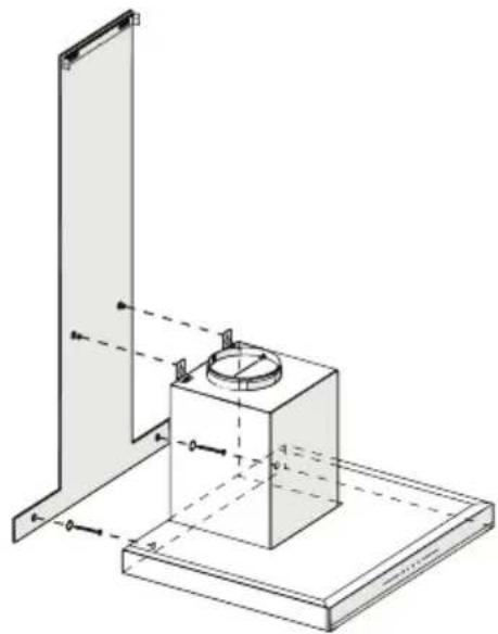
5.5 Installation of the Hood to the Chimney
Make the electrical connection of your hood before starting the installation of the Chimney. Slip the Chimney plates around the body.
Install the Chimney plate to the Chimney fastening plate that is secured to the wall from its upper outer edges (Figure 12).
(Figure 12)
- Inner Chimney
- 3.5x9.5 Screw
- Chimney Connection Plate
5 installation of appliance
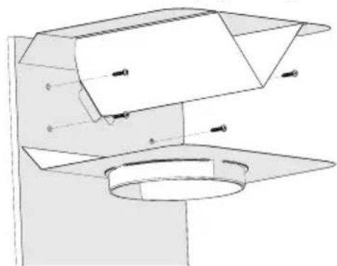
5.6 Installation of Air Baffle (BHCB 93640 BH)
While using with the carbon filter, air baffle is provided with your appliance with the aim of re-releasing the air which is cleaned with carbon filter from the perforated located on the Chimney. Assemble the air baffle as below.
(Figure 13)
There is a tab in the middle of the Chimney connection plate. Place the middle point of this tab on the line that is drawn perpendicular to the wall. Align horizontally and mark the holes where the connection plate will be mounted via a pen (Figure 13/A, B).
Drill the marked points with ∅6mm drill and insert two ∅6mm plastic dowels in the drilled holes (Figure 13/A, B).
Fix the Chimney connection plate to the wall with 3.9x22 screws (Figure 13/A, B).
For air baffle assembly, install point C, D, E, F with ∅6mm drill and ∅6mm plastic dowels (Figure 13).
(Figure 14)
-
Air Baffle
-
Plastic Chimney
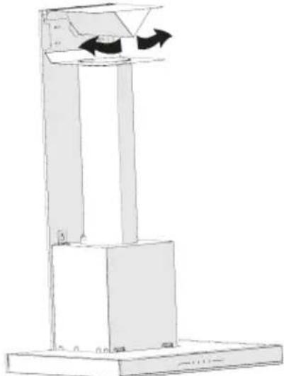
Attach the plastic Chimney adapter, which is included in the package, in the direction of the air baffle. Lock the Chimney adapter by turning it in the direction of the arrow (Figure 14).
natural_image
Technical line drawing of a mechanical component with no visible text or symbols(Figure 15)
Assemble the air baffle group with 3.9 x 22 screws from point C, D, E, F that you have already prepared (Figure 13).
Assemble the hood body (Figure 7).
natural_image
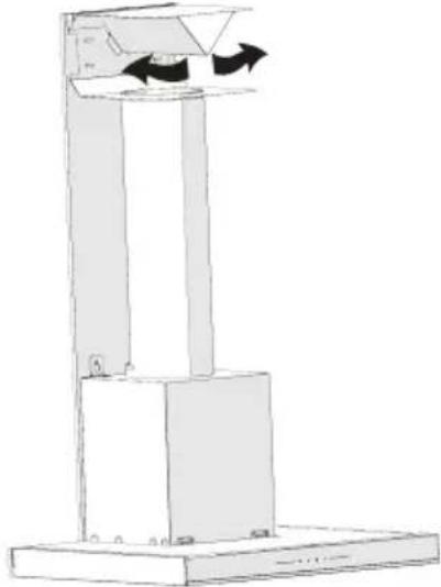
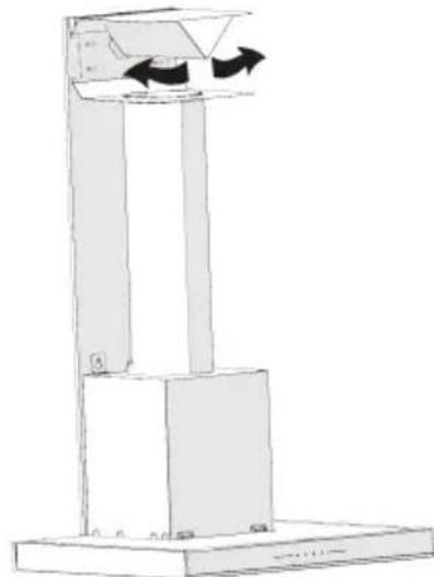
Simple line drawing of a vertical stand with arrows indicating motion or force direction (no text or symbols)(Figure 16)
- Aluminium Air Outlet Pipe
Make the air outlet pipe assembly (Figure 16).

Since twists and bends in the aluminium pipe will lead to reduction in the air suction power, avoid using twists and bends as much as possible.
Install the Chimney plates of the hood (Figure 12)
6 Troubleshooting
| Troubleshooting Root cause Help | ||
| Appliance is not working. | Check your fuses. Fuse may be blown, inspect and restore it. | |
| Appliance is not working. | Check the electrical connection. | Mains voltage shall be between 220 and 240 V. |
| Appliance is not working. | Check the electrical connection. | Check if other appliance in your kitchen operate. |
| Illumination light does not operate. | Check the electrical connection. | Mains voltage shall be between 220 and 240 V. |
| Illumination light does not operate. | Inspect the lamp switch. Lamp switch shall be at “on” position. | |
| Illumination light does not operate. | Inspect the lamps. The lamps of the appliance shall illuminate. | |
| Air inlet of the appliance is inadequate. | Inspect the grease filter. Under normal operating conditions, grease filter shall be cleaned at least once in a month. | |
| Air inlet of the appliance is inadequate. | Check the air discharge chimney. | The air discharge chimney shall be at “on” position. |
| Air inlet of the appliance is inadequate. | Inspect the carbon filter. The filters of the appliances with carbon filters shall be replaced once in every 3 months under normal conditions. | |
scatter
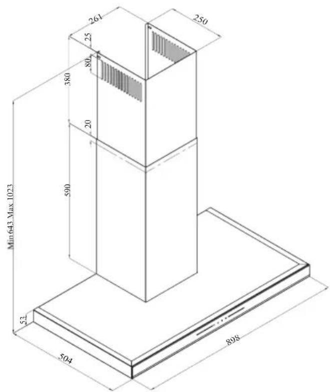
| n643 Max 1023 | 504 | 261 | 250 | |---|---|---|---| | 53 | | | | | | 590 | 380 | | | | | 20 | 80 | | | | | 25 | | | | | | | | | | | | | | | | | | | | | | | | | | | | | | | | | | | | | | | | | | | | | | | | | | | | | | | | | | | | | | | | | | | 898 | | | | The chart displays a single data point for 'n643 Max 1023' on the y-axis against an unlabeled x-axis variable. The y-axis is labeled as '504'. The x-axis is labeled as '53'. The y-axis is labeled as '590'. The data points are explicitly labeled with numbers (e.g., 261, 250, 898).natural_image
Technical line drawing of a ceiling structure with ventilation ducts and a black arrow indicating airflow direction (no text or symbols)(Abbildung 4)
natural_image
Technical line drawing of a mechanical assembly with a central component and support structure (no text or symbols)(Abbildung 9)
(Abbildung 10)
(a)(b)
Ok
natural_image
Simple line drawing of a container with liquid and a wavy top surface, no text or symbols present(Abbildung 12)
natural_image
Technical line drawing of a mechanical component with mounting flange and housing (no text or symbols)(Abbildung 15)
natural_image
Simple line drawing of a vertical platform with arrows indicating rotation or movement, no text or symbols present.(Abbildung 16)
BHCB 93640 B
BHCB 93640 BH
natural_image
Illustration of hands holding a circular device with arrows indicating process (no text or symbols)(Imagen 3)
natural_image
Technical diagram of a ceiling structure with an arrow indicating direction (no text or symbols present)(Imagen 4)
(Imagen 8)
natural_image
Technical line drawing of a mechanical assembly with a cylindrical component mounted on a base plate (no text or symbols)(Imagen 9)
(Imagen 10)
(a)(b)
natural_image
Simple line drawing of a container with a wavy top and side supports (no text or symbols)Ok Not Ok
(Imagen 11)
natural_image
Technical line drawing of a mechanical component with mounting flange and cylindrical base (no text or symbols)(Imagen 15)
natural_image
Diagram of a vertical cylindrical device with two arrows indicating directional flow or movement, mounted on a base (no text or symbols present)(Imagen 16)
natural_image
Technical diagram of a ceiling structure with an arrow indicating direction (no text or symbols present)(Figura 4)
natural_image
Technical line drawing of a mechanical assembly with a vertical support and base platform (no text or symbols)(Figura 9)
(Figura 10)
(Figura 11)
5.5 Instalarea hotei la tubul de evacuare
natural_image
Technical diagram of a mechanical assembly with no visible text or symbols(Figura 15)
natural_image
Simple line drawing of a vertical platform with two arrows indicating clockwise motion (no text or symbols)(Figura 16)
(Figure 1) (Figure 2) BHCB 93640 B

BHCB 93640 BH
Commandes et pièces
natural_image
Diagram of a kitchen ventilation system with airflow direction indicated by arrows (no text or symbols)(Figure 4)
natural_image
Technical line drawing of a mechanical assembly with a central component and support structure (no text or symbols)(Figure 9)
(Figure 10)
(Figure 11a/11b)
For air baffle assembly, install point C, D, E, F with ∅6mm drill and ∅6mm plastic dowels (Figure 13).

(Figure 14)
natural_image
Technical line drawing of a mechanical component with mounting flange and cylindrical base (no text or symbols)(Figure 15)
natural_image
Simple line drawing of a vertical platform with arrows indicating flow or movement (no text or symbols)(Figure 16)
natural_image
Illustration of hands using a mechanical tool to adjust a circular component with arrows indicating motion (no text or symbols)(Afbeelding 3)
natural_image
Diagram of a kitchen ventilation system with airflow direction indicated by arrows (no text or symbols)(Afbeelding 4)
natural_image
Technical line drawing of a mechanical assembly with a cylindrical component mounted on a base plate (no text or symbols)(Afbeelding 9)
(Afbeelding 10)
natural_image
Technical line drawing of a mechanical component with mounting flange and cylindrical base (no text or symbols)(Afbeelding 15)
natural_image
Simple line drawing of a vertical platform with arrows indicating rotation or movement, no text or symbols present.(Afbeelding 16)
Q S G B 3 J M m D o b
y00m06s30sl 1b3s lsymg3bbm36md
2 6m3s00 3s6g86y00 ls6y
2.1partialo3s
(6sbs8o 1)

(6s6s8o 2) BHCB 93640 B
BHCB 93640 BH
natural_image
Illustration of hands holding a circular device with a pointer and arrow indicating direction (no text or symbols)(6sbs8o 3)
zsdsmogon dmhymdommdou gmydym dggmogdo. dmhymdommdao zsdmoygbds 3 30 fghgommmzbo LED lsbsno. lsbsmogdo. dgls3gmymsq qssfjgloon dwqgl yzsbs dbnqosb, qssfjmosmgoi lssnou olmo lsfbobssmdqggam dodsmaugmydoo os dmblgbom lsbsno. sbsno lsbsmogdo qslsygbdmsq zsdgmngm ozg3g 36m3gquyns lsfgobssmdqggm osbdodqgg3mdoo (bsbso 3).
natural_image
Technical diagram of a ceiling structure with ventilation ducts and a black arrow indicating direction (no text or symbols)(6sbs8o 4)
- 36mqngd80
- მიდა კვამლსარინი
- გარე კვამლსარინი
- ∅150/120 ∂∂ 33∂μλυσόνούς υροςθύγισό
- 33sāmūsmōbōu āyādʒmōngāgāmo 3sāgāmo
- əməbəsəmɡdəməʊl əsəbɡəmədəməzəsbɡəm
- s6s6ymdou 8030
- 2x ἄgbsʒɔŋo 3s6ŋmo
- 2x ∅6 ∂∂ 3πυδρού ρομησιο
- 4x ∅10 ∂∂ 3πλυδσιού ρομηδρων
- 4x 5.5x60 390000000000000000000000000
- 2x M5x35 ἀγλυσορο 3s6μμού ἀγμόσοδού b6s6b0
natural_image
Technical line drawing of a mechanical assembly with a cylindrical component mounted on a base plate (no text or symbols)(6sbs8o 9)
qsofomgos zsdfmz0 zmmbyloom qos zsbsmszlgos zjogm6g yosdm6gsgjdyem lsdm6gsgm bhsbbg86g, aydqya dmyfoomgos bhsbbg8u (bsbsgo 9).
qssyy6gom M4 ἀŋsbsqgdɔ 5.5x60 lszɔqφού b̄nsb̄b̄g. qssdsz̄gμο zs̄d̄h̄m3o z̄qω̄μm̄b̄g 5.5x60 b̄nsb̄b̄ωο dm̄hyμδομ̄m̄d̄ou ὁqως ὁbs̄gμ s̄ml̄ḡd̄yμπο l̄sdəmb̄ψ̄sgm b̄sb̄z̄ḡḡou d̄j̄d̄z̄m̄d̄ωο (b̄sbs̄ḡo 9).
(6s6s8o 10)
(6s6s8o 12)
-
ἀσος 33δμλυσόνο
-
3.5x9.5 b6s660
-
33sāmūsǎnǎo bù āyāsāngādāgāmo 3sāgāmo
5.6 3576015 s46932001 dmb85g0 (BHCB 93640 BH)
natural_image
Technical line drawing of a mechanical component with no visible text or symbols(6s6s8o 15)
ωssyghgym 3sgnol sādhjzmol dvmz0 3.9 x 22 bhsbghdom dmdhsgngdym fghgogmghdo C, D, E, F (6sbsgo 13).
qssygbom 3sdgmzol 3m63glo (6sbs807).
natural_image
Simple line drawing of a vertical platform with two arrows indicating clockwise motion (no text or symbols)(6s6s8o 11)
- 3sŋmʊl ʒsdədʒgðo ʒmŋdɒbʊ dɔŋmo qssyʃgɔn 3sŋmʊl ʒsdədʒgðo dɔŋmo (6sbsʒo 16).

6 36m0g0g0g0g0g0g0g0g0g0g0g0g0g0g0g0g0g0g0g0g0g0g0g0g0g0g0g0g0g0g0g0g0g0g0g0g0g0g0g0g0g0g0g0g0g0g0g0g0g0g0
| 36m8cmg8d8o1smdmbgs | do#omsgno do#bbo qsbdsngds | |
| dmfymdomms s6dmydms. | dysdmfdgn d3gmcngdo. dglsdmmss, | d3gmo gqosof3s,dysdmfdgn qs ysdmg3smgomol. |
| dmfymdomms s6dmydms. | dysdmfdgn gmydgm dggmongs. | gmydgmjugmou ds8s y6qsoym2 220-240 3. |
| dmfymdomms s6dmydms. | dysdmfdgn gmydgm dggmongs. | dysdmfdgn, dmydsmdl omysds ub3s dmydommdgdo lsdbsgymmdo. |
| zsbsongs s6dmydms. | dysdmfdgn gmydgm dggmongs. | gmydgmjugmou ds8s y6qsoym2 220-240 3. |
| zsbsongs s6dmydms. | dysdmfdgn lsbsomlsgspdmonzgo. | lsbsomls gqosdmonzgo no y6qsoym2 smboosdo ,,hsmongmo". |
| zsbsongs s6dmydms. | dysdmfdgn lsbsomdo. dmfymdomndou lsbsomdo y6qss bssomdogbl. | |
| dmfymdommdol3sgnol dgdgmzo5sls3dsnolsqdmydms. | dysdmfdgn smydobol gomgmo. | 3gmydmoz 30mddgdo smydobol ygomls gomgmo y6qss zsswgmsgm o doboyda m3gdo gmmbgm. |
| dmfymdommdol3sgnol dgdgmzo5sls3dsnolsqdmydms. | dysdmfdgn 3sgnol gsmdadzgo 3sdmshobo. | 3sgnol gsmdadzgo 3sdmshobo y6qss oyml smboosdo ,,hsmongmo". |
| dmfymdommdol3sgnol dgdgmzo5sls3dsnolsqdmydms. | dysdmfdgn bsdaonol gomgmo. | 3gmydmoz 30mddgdo dmfymdommdol bsdaonls gomgmo y6qss dgsmmom 3 smgdo gmmbgm. |
(Figura 1)

(Figura 2) BHCB 93640 B
BHCB 93640 BH
natural_image
Illustration of hands holding a circular device with a knob, showing mechanical components and directional arrows (no text or symbols)(Figura 3)
natural_image
Technical diagram of a ceiling structure with ventilation grilles and a downward arrow indicating airflow or movement (no text or symbols)(Figura 4)
natural_image
Technical line drawing of a mechanical assembly with a central component and mounting base (no text or symbols)(Figura 9)
(Figura 10)
(Figura 11)
(Figura 12)
natural_image
Technical line drawing of a mechanical component with no visible text or symbols(Figura 15)
natural_image
Simple line drawing of a vertical stand with two arrows indicating clockwise motion, no text or symbols present.(Figura 16)
natural_image
Technical line drawing of a ceiling structure with mounting holes and a curved arrow indicating direction (no text or symbols)(Figura 4)
(Figura 8)
natural_image
Technical line drawing of a mechanical assembly with a cylindrical component mounted on a base plate (no text or symbols)(Figura 9)
(Figura 10)

(a)(b)
natural_image
Simple line drawing of a container with liquid and a wavy top surface, supported by two vertical supports (no text or symbols)Ok Not Ok
(Figura 11)
5.5 Montimi i aspiratorit me oxhakun
(Figura 12)
natural_image
Technical line drawing of a mechanical component with mounting flange and housing (no text or symbols)(Figura 15)
natural_image
Simple line drawing of a vertical structure with two arrows indicating rotation or movement, no text or symbols present.(Figura 16)
(Obrázek č. 1)

natural_image
Technical diagram of a ceiling structure with mounting holes and a directional arrow indicating motion (no text or symbols)(Obrázek č. 4)
natural_image
Technical line drawing of a mechanical assembly with a base platform and mounting bracket (no text or symbols)(Obrázek č. 9)
(Obrázek č. 10)
(Obrázek č. 11)
(Obrázek č. 12)
natural_image
Technical line drawing of a mechanical component with mounting flange and cylindrical base (no text or symbols)(Obrázek č. 15)
natural_image
Simple line drawing of a vertical stand with two arrows indicating direction, no text or symbols present(Obrázek č. 16)
(Obrázok č. 1)

natural_image
Technical line drawing of a ceiling structure with mounting holes and a black arrow indicating direction (no text or symbols)(Obrázok č. 4)
natural_image
Technical line drawing of a mechanical assembly with a cylindrical component mounted on a base plate (no text or symbols)(Obrázok č. 9)
(Obrázok č. 10)
(Obrázok č. 11)
(Obrázok č. 12)
(Obrázok č. 14)
natural_image
Technical line drawing of a mechanical component with no visible text or symbols(Obrázok č. 15)
natural_image
Simple line drawing of a vertical platform with arrows indicating direction, no text or symbols present(Obrázok č. 16)
(Rys. 1)
(Rys. 2) BHCB 93640 B
BHCB 93640 BH
natural_image
Technical diagram of a ceiling structure with mounting holes and a curved arrow indicating direction (no text or symbols)(Rys. 4)
(Rys. 8)
natural_image
Technical line drawing of a mechanical assembly with a cylindrical component mounted on a base plate (no text or symbols)(Rys. 9)
(Rys. 10)
(a)(b)
natural_image
Simple line drawing of a container with liquid and a wavy top surface, no text or symbols presentOk Not Ok
(Rys. 11)
(Rys. 13)
natural_image
Technical diagram of a mechanical component with labeled parts (no readable text or symbols)(Rys. 15)
natural_image
Simple line drawing of a vertical stand with arrows indicating direction, no text or symbols present(Rys. 15)
(Фигура 1)

natural_image
Simple line drawing of a box inside a house-shaped frame with arrows indicating direction (no text or symbols)natural_image
Technical diagram of a ceiling structure with internal components and a black arrow indicating direction (no text or symbols)(Фигура 4)
(Фигура 8)
natural_image
Technical line drawing of a mechanical assembly with a cylindrical component mounted on a base plate (no text or symbols)(Фигура 9)
(Фигура 10)
(Фигура 11)
(Фигура 7)
natural_image
Technical line drawing of a mechanical component with mounting flange and base plate (no text or symbols)(Фигура 15)
natural_image
Simple line drawing of a vertical platform with arrows indicating flow or movement (no text or symbols)(Фигура 16)
(Slika 2) BHCB 93640 B
BHCB 93640 BH
2.2 Tehnički podaci
| Model BHCB 93640 B BHCB | 93640 BH | |
| Napon napajanja 220-240V ~ 50 Hz | ||
| Snaga lampice 2x3 W | ||
| Snaga motora 210 W | ||
| Brzina protoka – 3. Nivo 645 m3/h | ||
| Klasa izolacije motora Klasa F | ||
| Klasa izolacije Klasa I | ||
natural_image
Illustration of hands using a mechanical device to adjust a circular component with a knob (no text or symbols)(Slika 3)
natural_image
Technical line drawing of a ceiling structure with mounting holes and a curved arrow indicating direction (no text or symbols)(Slika 4)
- Gurnite bravu aluminijskog filtera za masnoću prema naprijed.
- Zatim je lagano povucite prema dolje i izvucite je (Slika 4). U suprotnom možete saviti filter. Operite i isperite aluminijske filtere za masnoću tečnim deterdžentom i vratite aluminijske filtere za masnoću na njihova mjesta izvodeći gore na-vedene korake obrnutim redoslijedom. Ovaj filter sakuplja čestice masnoće u vazduhu.

- Proizvod
- Unutarnji dimnjak
- Vanjski dimnjak
- ∅150/120mm adapter za dimnjak
- Ploča za priključak na dimnjak
- Uputstvo za upotrebu
- Obrazac montaže
- 2x viseće ploče
- 2x ∅6mm plastični klip
- 4x ∅10mm plastični klip
- 4x 5,5x60 vijak za zidnu montažu
- 2x M5x35 vijak za pričvršćivanje viseće ploče
- 2x 3,9x22 vijak za ploču za priključak na dimnjak
- 2x podloške M4
- Zračna pregrada
- Plastični adapter (diverter zraka)
- 2x vijak pločice za priključak dimnjak 3,5x9,5
- Stezaljka za dimnjak
Informacije potrebne za pripremu lokacije prikladne za postavljanje nape date su u nastavku.
5 Ugradnja uređaja
5.3 Montaža na zid
- Zid mora biti ravan, prav i imati dovoljnu nosivost.
- Dubina rupa za bušenje mora biti u skladu s dužinom vijka.
- Isporučeni vijci i klipovi prikladni su za zidove od opeke. Za drugi građevinski materijal (npr. gipsani zid, ploča, porozni beton) koriste se odgovarajući učvrsni klipovi i matice.
(Slika 7)

OPREZ: Prije bušenja osigurajte da u neposrednoj blizini mjesta bušenja nema struje, plina ili vode.
natural_image
Technical line drawing of a mechanical assembly with a central component and base plate (no text or symbols)(Slika 9)
Držite aspirator za štednjak za njegovo kućište i stavite ga na montažne vijke na zidu i pritegnite vijke (Slika 9).
Ugradite podloške M4 na vijke na kačenje 5,5x60. Pričvrstite aspirator za štednjak s vijkom 5,5x60 na zid kroz otvor za montažu s unutarnje strane uređaja (Slika 9).
5 Ugradnja uređaja
(Slika 11)
5.5 Ugradnja nape na dimnjak
(Slika 12)
natural_image
Technical line drawing of a mechanical component with mounting flange and cylindrical base (no text or symbols)(Slika 15)
Sastavite grupu zračnih pregrada s vijcima 3,9 x 22 iz točke C, D, E, F koju ste već pripremili (Slika 13). Montirajte kućište aspiratora (Strana 12/ Slika 7).
natural_image
Simple line drawing of a vertical platform with arrows indicating direction (no text or symbols)(Slika 16)
natural_image
Simple line icon of a chimney emitting steam (no text or symbols)BHCB 93640 B - BHCB 93640 BH
RU
natural_image
Illustration of hands holding a circular mechanical component with arrows indicating motion or force (no text or symbols)(Рисунок 3)
natural_image
Technical diagram of a ceiling structure with mounting holes and a curved arrow indicating direction (no text or symbols)(Рисунок 4)
natural_image
Technical line drawing of a mechanical assembly with a central circular component and two vertical supports (no text or symbols)(Рисунок 9)
(Рисунок 10)
(Рисунок 11)
4 Очистка и уход
(Рисунок 12)
natural_image
Technical diagram of a mechanical component with labeled parts (no readable text or symbols)(Рисунок 15)
natural_image
Simple line drawing of a vertical stand with arrows indicating direction, no text or symbols present(Рисунок 16)
(2 cypet) BHCB 93640 B
BHCB 93640 BH
- Ішкі муржа
- Сырткы муржа
- Баскару тактасы
- Май түтқыш сүзгі
- Жарыктандыру
natural_image
Illustration showing a showerhead being held by hands, with arrows indicating the process (no text or symbols present)(3 сурет)
natural_image
Simple line drawing of a box inside a house-shaped frame with directional arrows (no text or symbols)natural_image
Technical diagram of a ceiling structure with ventilation ducts and a directional arrow indicating airflow or movement (no text or symbols)(4 cypet)
natural_image
Technical line drawing of a mechanical assembly with a central component and mounting base (no text or symbols)(9 сурет)
(10 cypet)
(11 cypet)