CM 11 - Multimeter BENNING - Free user manual and instructions
Find the device manual for free CM 11 BENNING in PDF.
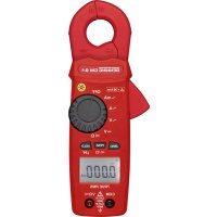
| Product Type | Digital Clamp Multimeter |
| Brand | BENNING |
| Model | CM 11 |
| Dimensions (L × W × H) | 190 × 60 × 40 mm |
| Weight | 265 g |
| Power Supply | 2 x 1.5 V batteries type R3 (IEC LR06, AA) |
| Battery Life | Approximately 250 hours (alkaline) |
| Display | LCD 3 1/2 digits, height 15 mm, max value 1999 |
| Auto Power Off | After approximately 10 minutes |
| AC Voltage Measurement | 200 V / 750 V, accuracy ±(1.5% + 5 digits) |
| DC Voltage Measurement | 200 V / 1000 V, accuracy ±(1.0% + 2 digits) |
| AC Current Measurement (clamp) | 200 A / 400 A, accuracy ±(3.0% + 3 digits) |
| Resistance Measurement | 200 Ω to 20 MΩ, accuracy ±(1.0% to 1.9% + digits) |
| Diode Test | Forward voltage displayed, threshold 0.4-0.8 V |
| Continuity Test | Audible signal for resistance < 50 Ω |
| Non-Contact Voltage Indicator (VoltSensor) | Phase detection ≥ 230 V AC, audible signal and red LED |
| HOLD Function | Memory of the measured value |
| Clamp Opening | 16 mm |
| Overvoltage Category | CAT III 1000 V / CAT IV 600 V |
| Protection Type | IP 30 (housing, no water protection) |
| Operating Temperature | 0 °C to 50 °C, humidity < 80% |
| Storage Temperature | -20 °C to +60 °C, humidity < 80% (without batteries) |
| Included Accessories | Red and black test leads (1.4 m), case, batteries, instruction manual |
| Care and Cleaning | Clean with a dry cloth, avoid solvents. Replace batteries if battery symbol appears |
| Safety | Follow instructions: do not use on circuits > 1000 V DC / 750 V AC, use CAT III/IV caps |
Frequently Asked Questions - CM 11 BENNING
User questions about CM 11 BENNING
0 question about this device. Answer the ones you know or ask your own.
Ask a new question about this device
Download the instructions for your Multimeter in PDF format for free! Find your manual CM 11 - BENNING and take your electronic device back in hand. On this page are published all the documents necessary for the use of your device. CM 11 by BENNING.
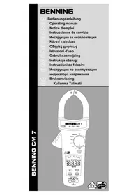
USER MANUAL CM 11 BENNING
Multilingual manuals on included CD and at
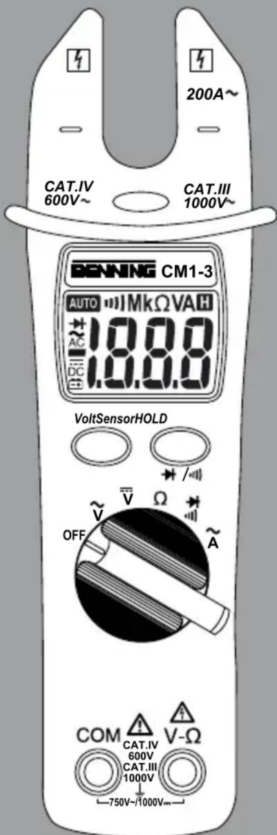
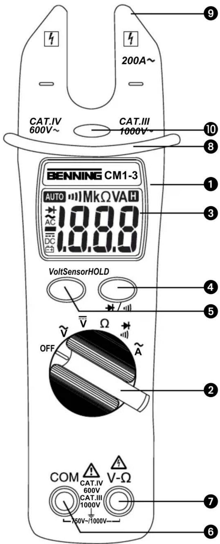
Bild 1: Gerätefrontseite
Fig.1: Front tester panel
Fig. 1: Panneau avant de l'appareil
Fig.1: Parte frontal del equipo
Obr.1: Predni strana pristroje
Eikova 1: Mtnpootivn oyn
Digital current clamp multimeter for
- AC current measurements
- AC voltage measurements
- DC voltage measurements
- resistance measurements
- diode tests
- continuity tests
Table of contents
- User instructions
- Safety instructions
- Scope of delivery
- Device description
- General information
- Ambient conditions
- Electrical specifications
- Measuring with the BENNING CM 1-3
- Maintenance
- Technical data of measuring accessories
- Environmental note
1. User instructions
This operating manual is intended for
- skilled electricians and
- electrotechnically trained personnel.
The BENNING CM 1-3 is intended for measurements under dry ambient conditions. It must not be used in electrical circuits with a nominal voltage higher than 1000V DC and 750V AC (see section 6 Ambient conditions for details).
The following symbols are used in this operating manual and on the BENNING CM 1-3:

Application around and removal from HAZARDOUS LIVE conductors is permitted.

Warning of electrical danger!
Indicates instructions which must be followed to avoid danger to persons.

Attention! Must comply with documentation!
This symbol indicates that the information provided in the operating manual must be complied with in order to avoid risks.

This symbol on the BENNING CM 1-3 indicates that the BENNING CM 1-3 is equipped with protective insulation (protection class II).

This symbol appears on the display to indicate a discharged battery.

This symbol designates the "diode test" field.

This symbol designates the "continuity test" field.
The buzzer is intended for acoustic result output.

(DC) Direct voltage

(AC) Alternating voltage or current

Ground (voltage against ground)
2. Safety instructions
The instrument is built and tested in accordance with
DIN VDE 0411 Part 1/ EN 61010-1
DIN VDE 0411 Part 2-032/EN 61010-2-032
DIN VDE 0411 Part 2-033/EN 61010-2-033
DIN VDE 0411 Part 031/EN 61010-031
and has left the factory in perfectly safe technical condition.
To preserve this condition and to ensure safe operation of the device, the user must observe the notes and warnings given in these instructions at all times. Improper handling and non-observance of the warnings might involve severe injuries or danger to life.

WARNING! Be extremely careful when working with bare conductors or main line carrier! Contact with live conductors will cause an electric shock!

The BENNING CM 1-3 must be used in electrical circuits of overvoltage category III with a conductor for a maximum of 1000V to earth or of overvoltage category IV with a conductor for a maximum of 600V to earth only.
Only use suitable measuring leads for this. With measurements within measurement category III or measurement category IV, the projecting conductive part of a contact tip of the measuring leads must not be longer than 4mm
Prior to carrying out measurements within measurement category III and measurement category IV, the push-on caps provided with the set and marked with CAT III and CAT IV must be pushed onto the contact tips. The purpose of this measure is user protection.
Please observe that work on live parts and electrical components of all kinds is dangerous! Even low voltages of 30 V AC and 60 V DC may be dangerous to human life!

Before starting the current clamp multimeter, always check the device as well as all measuring leads for damages.
If it can be assumed that safe operation is no longer possible, switch the device off immediately and secure it against unintended operation.
Safe operation can be assumed to be no longer possible, if
- the device or the measuring leads exhibit visible damages,
- the device no longer works,
- the device has been stored under unfavourable conditions for a longer period of time,
- the device was exposed to extraordinary stress during transport.

In order to prevent danger
- do not touch the bare measuring probe tips of the measuring leads,
- insert the measuring leads into the respectively designated measuring socket of the multimeter.
3. Scope of delivery
The scope of delivery of the BENNING CM 1-3 comprises:
3.1 One BENNING CM 1-3,
3.2 One safety measuring lead, red (L = 1.4m)
3.3 One safety measuring lead, black (L = 1.4m)
3.4 One compact protective pouch,
3.5 Two 1,5 V micro batteries for initial assembly is integrated into the device,
3.6 One operating manual.
Parts subject to wear:
- The BENNING CM 1-3 is supplied by means of two integrated 1,5 V micro batteries (IEC 6 LR 03).
- The safety measuring leads mentioned above (tested accessories, 044145) comply with CAT III 1000 V and are approved for a current of 10 A.
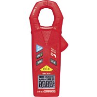
4. Device description
See figure 1: Device front
The display and operating elements shown in figure 1 are designated as follows:
Housing
2 Rotary switch, for selecting the desired function,
-OFF
- AC voltage measurement
DC voltage measurement
-resistancemeasurement
- diode and continuity test with buzzer
- AC current measurement
3 Digital display (liquid-crystal type) with following indications:
- measurement reading with max. indication 1999
-polarityindication
-decimalpoint
- symbol for discharged battery
- measurement reading retained (hold function)
- selected continuity test with buzzer
HOLD button (hold function)/ change-over button (diode and continuity test)
5 VoltSensor key, for determining AC voltage to earth,
COM jack, common jack for voltage/ resistance measurements, continuity and diode tests,
7 Jack (positive 1), for V and
Bulge for current clamp, protects against contact with conductor,
Open fork for inserting and gripping the single conductor containing AC current.
LED, for voltage indicator
) This is what the automatic polarity indication for DC voltage refers to
5. General information
5.1 General information on the current clamp multimeter
5.1.1 The digital display ③ is a 3 12 -digit LC display with a font size of 15 ~mm and a decimal point. The highest numerical value to be displayed is 1999.
5.1.2 The polarity indication 3 works automatically. Only a polarity contrary to the jack definition is indicated with ^-
5.1.3 The range exceedance is indicated by "OL" or "-OL" and partly by an acoustic warning. Attention, no indication and warning in case of overload!
5.1.4 Measured value storage "HOLD": Press the "HOLD" key 4 to store the measuring result. At the same time, the display shows the "H" symbol. Press the key again to switch back to the measuring mode.
5.1.5 The nominal measuring rate of the BENNING CM 1-3 is 1.5 measurements per second.
5.1.6 The BENNING CM 1-3 is switched off automatically after approx. 10 minutes. It can only be switched on again by switching the rotating switch off and on again.
5.1.7 Temperature coefficient of the measured value: 0.2 × (stated measuring accuracy) /^ C < 18^ C or >28^ C , related to the value for the reference temperature of 23^ C .
5.1.8 The BENNING CM 1-3 is supplied by means of two 1,5V micro batteries (IEC 6 LR 03).
5.1.9 If the battery voltage falls below the specified operating voltage of the BENNING CM 1-3, a battery symbol appears on the display.
5.1.10 The battery life is approx. 250 hours (alkaline battery).
5.1.11 Dimensions of the BENNING CM 1-3: (L × W × H) = 190 × 60 × 40 ~mm Weight: 265 ~g
5.1.12 The enclosed safety measuring leads are explicitly intended for the nominal voltage and the nominal current of the BENNING CM 1-3. The measuring tips can be protected by caps and can be clipped onto the underside of the unit for easier transport and for certain measuring tasks.
5.1.13 Fork opening: 16 mm
6. Ambient conditions
- The BENNING CM 1-3 is intended for measurements under dry ambient conditions,
Maximum barometric height for measurements: 2000m - Overvoltage category / installation category: IEC 60664-1/ IEC 61010-1 → 600 V category IV; 1000 V category III
- Contamination class: 2,
Protection category: IP 30 (DIN VDE 0470-1 IEC/ EN 60529)
3 - first index: protection against access to dangerous parts and protection
against solid impurities of a diameter >2.5mm
0 - second index: no protection against water
- Operating temperature and relative air humidity:
For operating temperatures from 0^ to 30^ : relative air humidity lower than 80% ,
For operating temperatures from 31^ to 40^ : relative air humidity lower than 75% ,
For operating temperatures from 41^ to 50^ : relative air humidity lower than 45% ,
- Storage temperature: The BENNING CM 8 can be stored at temperatures between -20 °C and +60 °C (air humidity 0 to 80%). During storage, the battery should be removed.
7. Electrical specifications
Note: The measuring accuracy is specified as the sum of:
-
a relative part of the measured value and
-
a number of digits (i.e. counting steps of the last digit).
This measuring accuracy applies to temperatures from 23^ ± 5^ and a relative air humidity lower than 80% .
7.1 AC voltage ranges
The input resistance is 2M in parallel 100pF . The measurement reading is obtained by rectification of average reading and displayed as actual value.
| Measuring range Resolution Measurement accuracy Overload protection | ||
| 200 V 0.1 V | ± (1.5 % of reading + 5 digits) in frequency range 50 Hz - 500 Hz | 750 V eff 1000 DC voltage |
| 750 V 1 V | ± (1.5 % of reading + 5 digits) in frequency range 50 Hz - 500 Hz | 750 V eff 1000 DC voltage |
7.2 DC voltage ranges
The input resistance is 2M
| Measuring range Resolution Measurement accuracy Overload protection | |||
| 200 V 0.1 V | ± (1.0 %) | of reading + 2 digits) | 750 V 1000 DC voltage |
| 1000 V 1 V | ± (1.0 %) | of reading + 2 digits) | 750 V 1000 DC voltage |
7.3 AC current ranges
(Current-fork opening embraces AC wire).
| Measuring range Resolution Measurement accuracy Overload protection | ||
| 200 A 0.1 A | ± (3.0 % of the measured value + 3 digits) within the frequency range 50 Hz – 60 Hz | 400 A |
Additional error in parallel current-conducting wire: < 0.08A / A
7.4 Resistance measuring ranges
Overload protection for resistance measurements: 600V_eff
| Measuring range | Resolution | Measuring accuracy | Max. open-circuit voltage |
| 200 Ω 0.1 Ω | ± (1.0 % of the measured value+ 5 digits) | 1.3 V | |
| 2 kΩ | 1 Ω | ± (1.0 % of the measured value + 2 digits) | 1.3 V |
| 20 kΩ | 10 Ω | ± (1.0 % of the measured value + 2 digits) | 1.3 V |
| 200 kΩ | 100 Ω | ± (1.0 % of the measured value + 2 digits) | 1.3 V |
| 2 MΩ 1 kΩ | ± (1.0 % of the measured value + 2 digits) | 1.3 V | |
| 20 MΩ | 10 kΩ | ± (1.9 % of the measured value + 5 digits) | 1.3 V |
7.5 Diode and continuity test
The stated measuring accuracy applies to a range between 0.4V and 0.8V . Overload protection: 600V_eff
The integrated buzzer sounds at a resistance R lower than 50 .
| Measuring range | Resolution Measuring accuracy | Max. measuring current | Max. open-circuit voltage | |
| → | 1 mV | ± (1.5 % of the measured value + 0.05 V) | 1.5 mA 3.0 V | |
8. Measuring with the BENNING CM 1-3
8.1 Preparing the measurement
Operate and store the BENNING CM 1-3 at the specified storage and operating temperatures only! Do not permanently expose the device to sunlight.
- Check stated nominal voltage and nominal current on the safety measuring leads. Nominal voltage and current of the enclosed safety measuring leads comply with the respective values of the BENNING CM 1-3.
- Check insulation of the safety measuring leads. If the insulation is damaged, the safety measuring leads must be replaced immediately.
- Check the safety measuring leads for continuity. If the conductor in the safety measuring lead is interrupted, replace the safety measuring leads immediately.
Before selecting another function by means of the rotary switch 2, disconnect the safety measuring leads from the measuring point. - Strong sources of interference in the vicinity of the BENNING CM 1-3 might involve unstable readings and measuring errors.
8.2 Voltage measurements

Do not exceed the maximum permitted voltage with respect to earth potential! Electrical danger!
The highest voltage that may be applied to the jacks
-
COM jack 6
-
jack for V and 7
of the BENNING CM 1-3 against ground is 1000V
- Select the desired function (V AC) or (V DC) by means of the rotary switch 2 of the BENNING CM 1-3.
- Connect the black safety measuring lead to the COM jack 6 of the BENNING CM 1-3.
- Connect the red safety measuring lead to the jack for V and of the BENNING CM 1-3.
- Bring the safety measuring leads into contact with the measuring points and read the measured value on the digital display 3 of the BENNING CM 1-3.
See figure 2:
DC voltage measurement
See figure 3:
AC voltage measurement
8.3 Current measurements
8.3.1 Preparing the measurement
Operate and store the BENNING CM 1-3 at the specified storage and operating temperatures only! Do not permanently expose the device to sunlight.
- Strong sources of interference in the vicinity of the BENNING CM 1-3 might involve unstable readings and measuring errors.

Do not apply any voltage to the output contacts of the BENNING CM 1-3! Any possibly connected safety measuring leads have to be removed.
8.3.2 Current measurements
- Select the desired function (A) by means of the rotary switch 2 of the BENNING CM 1-3.
- Push the fork over the conductor wire. The conductor wire must be in the open area.
- Read the value indicated on the digital display ③.
See figure 4:
AC current measurement
8.4 Resistance measurements
- Select the function () by means of the rotary switch 2 of the BENNING CM 1-3.
- Connect the black safety measuring lead to the COM jack 6 of the
BENNING CM 1-3.
- Connect the red safety measuring lead to the jack for V and of the BENNING CM 1-3.
- Bring the safety measuring leads into contact with the measuring points and read the measured value on the digital display 3 of the BENNING CM 1-3.
Note:
- To obtain a correct measurement, ensure that no voltage is applied to the measuring point.
- With small resistances, the measuring result can be improved by measuring the resistance of the safety measuring leads beforehand by short-circuiting the measuring tips and subtracting the reading obtained from the resistance measured.
See figure 5: Resistance measurement
8.5 Diode tests
- Select the function (→) by means of the rotary switch 2 of the BENNING CM 1-3 and press the HOLD key "diode test".
- Connect the black safety measuring lead to the COM jack 6 of the BENNING CM 1-3.
- Connect the red safety measuring lead to the jack for V, ⑦ of the BENNING CM 1-3.
- Bring the safety measuring leads into contact with the diode connections and read the measured value on the digital display 3 of the BENNING CM 1-3.
- For a standard Si diode applied in conduction direction, a conduction voltage between 0.400V and 0.900V is displayed. "000" indicates a short-circuit inside the diode. "OL" indicates an interruption inside the diode.
- For a diode applied in reverse direction, "OL" is indicated. If the diode is defective, "000" or other values are indicated.
See figure 6: Diode test/ continuity test with buzzer
8.6 Continuity tests with buzzer
- Select the function (▶by means of the rotary switch 2 of the BENNING CM 1-3 and press the HOLD▶key „continuity test".
- Connect the black safety measuring lead to the COM jack 6 of the BENNING CM 1-3.
- Connect the red safety measuring lead to the jack for V, of the BENNING CM 1-3.
- Bring the safety measuring leads into contact with the measuring points. If the line resistance between the COM jack 6 and the jack for V, 7 falls below 50 , the integrated buzzer of the BENNING CM 1-3 sounds.
See figure 6: Diode test/ continuity test with buzzer
8.7 Voltage indicator
The voltage indicator function is possible from each position of the rotary switch. No measuring leads are required as voltage indicator (non-contact detection of an alternating field). The detector is located on the upper part of the device behind the LED. By pressing the "VoltSensor" key 5, the display indication disappears (if the display is switched on). If a phase voltage is localized, this is indicated by an acoustic signal and a red LED signal 10. An indication is made in earthed AC current networks only! The phase can be determined by means of a single-pole measuring lead.
Practical hint:
Interruptions (cable breaks) in cables lying around openly such as e.g. cable reels, fairy lights etc. can be traced from the feeding point (phase) to the point of interruption.
Functional range: ≥ 230V
See figure 7: Voltage indicator with buzzer
8.7.1 Phase test
- Connect the black safety measuring lead to the COM jack 6 of the BENNING CM 1-3.
- Bring the safety measuring lead into contact with the measuring point of the system part and press the „VoltSensor“ key ⑤.
- If the red LED lights 10 and if there is an acoustic signal, the phase of an earthed AC voltage is applied to this measuring point (system part).
9. Maintenance

Before opening the BENNING CM 1-3, strictly observe that the device is free of voltage! Electrical danger!
Working on the opened BENNING CM 1-3 under voltage must be carried out
by skilled electricians special precautions for the prevention of accidents only!
Make sure that the BENNING CM 1-3 is free of voltage as described below before opening the device:
- First, remove both safety measuring leads from the object to be measured.
- Then, remove both safety measuring leads from the BENNING CM 1-3.
- Switch the rotary switch 2 to position "OFF".
9.1 Securing the device
Under certain circumstances, safe operation of the BENNING CM 1-3 might no longer be ensured, e.g. in case of:
- visible damages of the housing,
- incorrect measuring results,
- recognizable consequences of prolonged storage under inadmissible conditions and
- recognizable consequences of extraordinary stress due to transport.
In such cases, immediately switch off the BENNING CM 1-3, disconnect it from the measuring points and secure it against further use.
9.2 Cleaning
Clean the exterior of the device with a clean dry cloth (exception: special cleaning wipers). Do not use any solvents and/or abrasives to clean the device.
Make sure that the battery compartment and the battery contacts are not contaminated by leaking battery electrolyte.
If there are electrolyte contamination or white deposits in the area of the battery or the battery compartment, clean these areas as well by means of a dry cloth.
9.3 Battery replacement

Before opening the BENNING CM 1-3, strictly observe that the device is free of voltage! Electrical danger!
The BENNING CM 1-3 is supplied by means of two integrated 1.5V micro batteries. Battery replacement (see figure 8) is required, if the battery symbol appears on the display Proceed as follows to replace the battery:
- Disconnect the safety measuring leads from the measuring circuit.
- Remove the safety measuring leads from the BENNING CM 1-3.
- Switch the rotary switch 2 to position "OFF".
-
Put the BENNING CM 1-3 face down and unscrew the screw of the battery compartment cover.
-
Lift off the battery compartment cover from the bottom part of the battery compartment.
-
Remove the discharged battery from the battery compartment.
- Insert the new batteries into the battery compartment observing correct polarity.
- Lock the battery compartment cover into place on the bottom part and tighten the screw.
See figure 8: Battery replacement

Make your contribution for environmental protection! Do not dispose of discharged batteries via the household waste. Instead, return them to a collecting point for discharged batteries or spezial waste. Please look for information in your community's facilities.
9.4 Calibration
Benning guarantees compliance with the technical and accuracy specifications stated in the operating manual for the first 12 months after the delivery date.
To maintain accuracy of the measuring results, the device must be recalibrated in regular intervals by our factory service. We recommend recalibrating the device once a year. For this purpose, send the device to the following address:
10. Technical data of measuring accessories
- Standard: EN 61010-031,
- Maximum rated voltage to earth ( 12 ) and measuring category:
With push-on caps: 1000 V CAT III, 600 V CAT IV,
Without push-on caps: 1000 V CAT II,
Maximum rated current: 10 A,
- Protection class II (回), continuous double or reinforced insulation,
- Contamination class: 2,
Length: 1.4m AWG 18 - Ambient conditions:
Maximum barometric height for measurements: 2000m
Temperature: 0^ to +50^ , humidity 50% to 80%
- Only use the test leads if in perfect and clean condition as well as according to this manual, since the protection provided could otherwise be impaired.
- Replace the measuring leads, if the insulation is damaged or if the conductor/connector is interrupted.
- Do not touch the bare contact tips of the measuring leads. Only touch the area intended for your hands!
- Insert the bent terminals into the testing or measuring device.
11. Environmental note
At the end of product life, dispose of the unserviceable device via appropriate collecting facilities provided in your community.
(DC) Tension continue.

Viz obrakek 7: Indikator napeti's bzucakem
8.7.1 Kontrola fázi
npi6op n3oJnpOBaH dIy 3aunTbI OT npNKOCHOBHeN (KJIacc 3aunTbI II).

3TOT CnBON NOBJIeTcHa INDukaunn dJa pa3pJxehHOH
6atapeyn.

Pexim npOBepKn DIOoB.

3TOT CMMBOJ xapaKTePn3yET dnaNa30H «KoHTpOJIb npoxOxJdHnIa
TOKa). 3yMMep cnYxNIT nIЯ akCyTnueCKO BbIaUn pe3yIbTaTa.

(DC)-Obo3haaetnoctoHHoeHanpJxKeHne

(AC)-O6o3Hauaet nepemehhoe HapxkeHne nn TOK

Macca (Haprrxhe OTHOCHTbHO 3emn).
2. Yka3aHnNo TeXnKe 6e3OnacHOCTN
DAnHHbI npH6Op cnpoeKTHPOBAH nN3ROTOBJIe H COOTBeTCTBnC O CTaHapTOM
DIN BDE 0411 yactb 1/EN 61010-1
DIN VDE 0411 qactb 2-032/EN 61010-2-032
DIN VDE 0411 yactb 2-033/EN 61010-2-033
DIN VDE 0411 yactb 031/EN 61010-031.
8.7 HndnkaTop HanpjaKeHna
Функци Индкаторпанряженьо3MOxHаВКAKOM NOLOXKeHIN NOBOPOTHOBOblIOUaTeI.ИЗмерпелбныпpoBOdaВКаueCTBEИнДИкATOPaHnprJxHЯ He Tpe6bYTOc(pernctpaunnpemehHoro noJIg63 npNKoCHOBeHnry).ВВерхнчactn np6bopa 3a CBeTOnIOOm pacnoJIOxKeH npEmHbI DaTHNK.PnHaximeHa KONky «VoltSensor» racHTdncJIeNHNkaun(ecn OH6bl BKNIOUeH).PpI loKan3aunФa3OBOrO HAnpJxHEnra Pa3daeTc3ByKOBoCnHAN 3aropaeTcKpaChbICBeToND01.NHdkauNpOIN3BODITcTOJbKO npn 3a3eMNEHHbIX cetAx nepemeHHoro ToKa!C NOMuBIO ODHONOCHORO n3МерпелбHorO npOBODMOxHo TaKke OnpeDenTbФa3y.
PpakTnueckn COBET:
npepbibAHnna (noIOMKn Ka6eJ) B OTKpbIto npoIooKeHHbIX Ka6eJx, HapnPmep B Ka6eNbHbix 6apabahax, npJnHdx x T.D., MOKHO npocneKnbAtb OT MeCTa BBODa nITAHnna (pa3bl) Do MeCTa npepbibAHn.
Pn6op BENNING CM 1-3 pa6oTaet ot DByx 6aTapeek Tn IEC 6 LR 03 1,5 B.
3aMeHa 6aTapeiKn (CMOTpn pnc.8) Heo6xOIMMa TOrda, KOrDa Ha INnKaun NoBJIETcCmBOJ 6aTapeiKn.
Tak 3aMeHnTe 6aTapeuKy:
- OToeDInHnTe np6op BENNING CM 1-3 ot n3MePntJbHOu cenH,
- 3BLeKeNTe IN3MePHTeHbHbIe npOBoa I3 IN3MePHTeHbHbIX rHe3d npIn6opa
-Перевади-tepekeNIOuateIb 2В nIoXeHne «OFF» [BbIKIOUeHo].