SB133 - Single disc machine Ghibli - Free user manual and instructions
Find the device manual for free SB133 Ghibli in PDF.
Frequently Asked Questions - SB133 Ghibli
Questions des utilisateurs sur SB133 Ghibli
0 question sur cet appareil. Repondez a celles que vous connaissez ou posez la votre.
Poser une nouvelle question sur cet appareil
Download the instructions for your Single disc machine in PDF format for free! Find your manual SB133 - Ghibli and take your electronic device back in hand. On this page are published all the documents necessary for the use of your device. SB133 by Ghibli.
USER MANUAL SB133 Ghibli
The machine identification data and "CE" marking are located on the plate on the machine body.
It is advisable to note the machine model and serial number on the table on the next page.
FR
DONNÉES D'IDENTIFICATION
(Translation of original instructions)
FR Français FR-1
Thank you for choosing one of our cleaning products.
The floor cleaner you have purchased has been designed to satisfy users in terms of ease of use and reliability.
We are aware that, in order to remain so over time, a good product requires continuous updates aimed at satisfying the expectations of those who use it daily. To this end, we hope that you will be not only a satisfied customer but also a partner who does not hesitate to let us know your views and ideas resulting from personal experience on a day-to-day basis.
Contents
1.1 INTRODUCTION EN-3
1.2 - INTENDED USE OF THE MACHINE EN-3
1.3 - NON-INTENDED USE OF THE MACHINE EN-3
2.1 COMPONENT ASSEMBLY EN-3
2.1.a - Positioning the handle EN-3
2.1.b - Electrical machine handle/body connection EN-3
2.1.c - Assembling the cable reel supports EN-3
2.1.d - Assembling the brush EN-4
2.1.e - Assembling the pad holder EN-4
2.1.f - Assembling the tank (Optional) EN-4
2.1.g - Assembling the suction unit (Optional) EN-5
2.1.h - Assembling additional weight (Optional) EN-5
2.1.i - Electrical connection.. EN-5
3.1 KNOWLEDGE OF THE MACHINE EN-5
4.1 ADJUSTING HANDLE TILT EN-6
5.1 GUIDE HANDLE EN-6
6.1 OPERATION EN-6
6.1.a - Checks before use EN-6
6.1.b - Starting the machine EN-6
6.1.c - Using the machine EN-7
6.1.d - Double speed (if present) EN-7
6.1.e - End of use and turning off EN-8
6.1.f-Transport EN-8
7.1 MAINTENANCE AND CLEANING EN-8
7.1.a - Cleaning the machine.. EN-8
7.1.b - Emptying and cleaning the water tank (optional) EN-8
7.1.c - Replacing the brush EN-9
7.1.d - Replacing the pad EN-9
TROUBLESHOOTING .EN-10
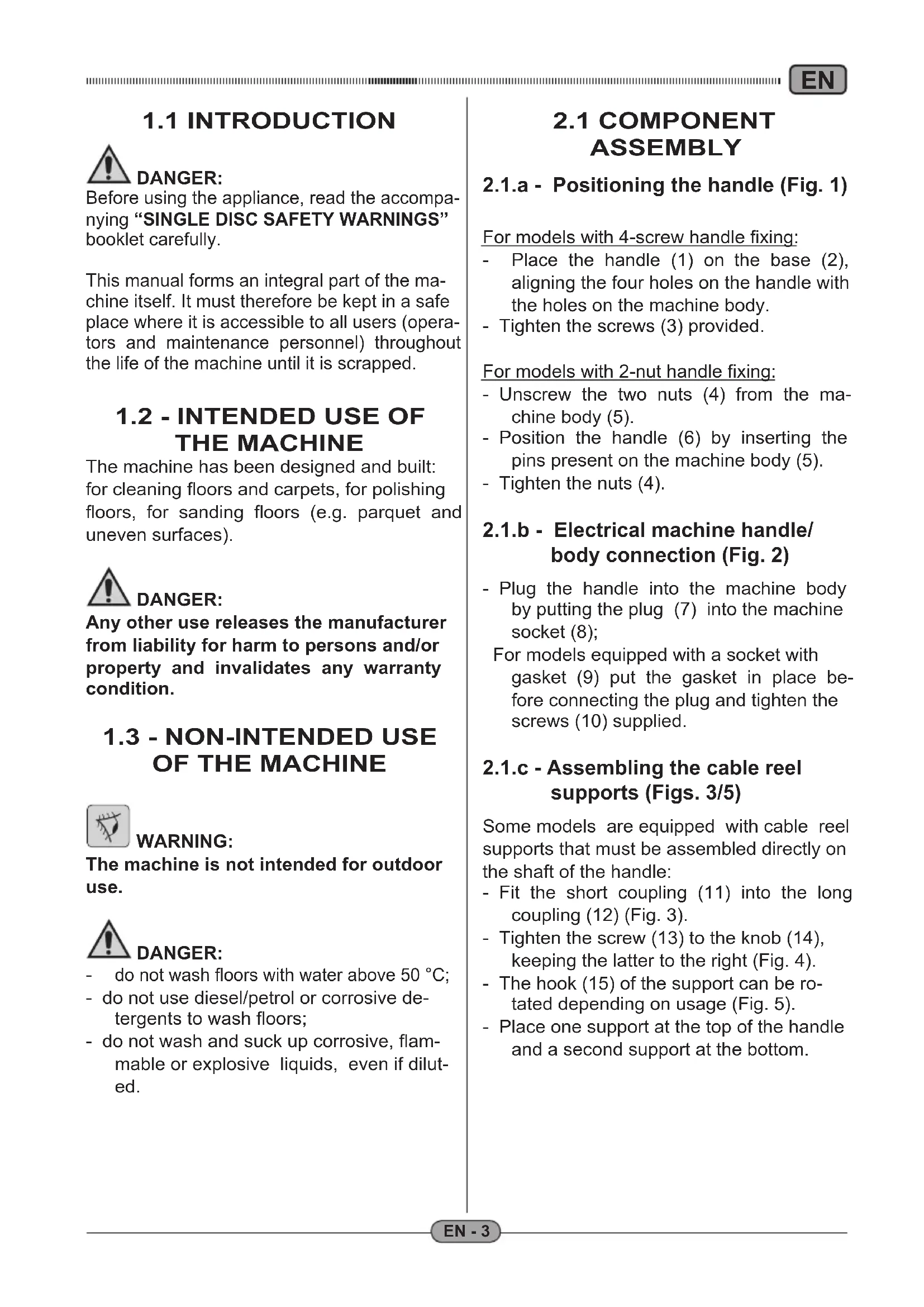
1.1 INTRODUCTION

DANGER:
Before using the appliance, read the accompanying "SINGLE DISC SAFETY WARNING" booklet carefully.
This manual forms an integral part of the machine itself. It must therefore be kept in a safe place where it is accessible to all users (operators and maintenance personnel) throughout the life of the machine until it is scrapped.
1.2 - INTENDED USE OF THE MACHINE
The machine has been designed and built: for cleaning floors and carpets, for polishing floors, for sanding floors (e.g. parquet and uneven surfaces).

DANGER:
Any other use releases the manufacturer from liability for harm to persons and/or property and invalidates any warranty condition.
1.3 - NON-INTENDED USE OF THE MACHINE

WARNING:
The machine is not intended for outdoor use.

DANGER:
- do not wash floors with water above 50^ ;
- do not use diesel/petrol or corrosive detergents to wash floors;
- do not wash and suck up corrosive, flammable or explosive liquids, even if diluted.
2.1 COMPONENT ASSEMBLY
2.1.a - Positioning the handle (Fig. 1)
For models with 4-screw handle fixing:
- Place the handle (1) on the base (2), aligning the four holes on the handle with the holes on the machine body.
- Tighten the screws (3) provided.
For models with 2-nut handle fixing:
- Unscrew the two nuts (4) from the machine body (5).
- Position the handle (6) by inserting the pins present on the machine body (5).
- Tighten the nuts (4).
2.1.b - Electrical machine handle/ body connection (Fig. 2)
- Plug the handle into the machine body by putting the plug (7) into the machine socket (8);
For models equipped with a socket with gasket (9) put the gasket in place before connecting the plug and tighten the screws (10) supplied.
2.1.c - Assembling the cable reel supports (Figs. 3/5)
Some models are equipped with cable reel supports that must be assembled directly on the shaft of the handle:
- Fit the short coupling (11) into the long coupling (12) (Fig. 3).
- Tighten the screw (13) to the knob (14), keeping the latter to the right (Fig. 4).
- The hook (15) of the support can be rotated depending on usage (Fig. 5).
- Place one support at the top of the handle and a second support at the bottom.
2.1.d - Assembling the brush (Fig. 6)
- Tilt the machine, pivoting, with the handle straight, with your feet on the wheels and place it on the handle.
- Place the brush (16) on the base of the machine, fitting the appropriate butterfly coupling (17).
- Make a half turn in the direction of the arrow (A) to fit in the brush (16).
- Put the machine back in position.
- When rotation starts, the brush will end fitting.
To disassemble the brush, tilt machine and turn the brush (16) in the opposite direction to that shown by the arrow (A).

WARNING:
Use only brushes supplied by the manufacturer for the specific machine model. Using other types of brushes can compromise the safety of the machine.
2.1.e - Assembling the pad holder (Figs. 6-7)
- Tilt the machine, pivoting, with the handle straight, with your feet on the wheels and place it on the handle.
- Place the pad holder (18) on the pad (19) being careful to centre it properly to avoid unbalancing the rotation.
- Place the pad holder (18) complete with pad, on the base of the machine, fitting the appropriate butterfly coupling, as described in the "Assembling the brush" paragraph.
To disassemble the pad holder, tilt the machine and turn it in the opposite direction to that shown by the arrow (A).

WARNING:
Use only pads supplied by the manufacturer for the specific machine model. Using other types of pads can compromise the safety of the machine.
2.1.f - Assembling the tank (optional) (Figs. 8/14)
- Loosen the two screws (20) or the knob (21) on the upper support (22) of the handle, depending on the machine model (Fig. 8).
Make sure that the lower support (27) rests on the plate located on the handle rod (Fig. 11). - Screw the chain (23) onto the top of the tank (24) (Fig. 9).
- Connect the tube (25) into the fitting (26) at the bottom of the tank (24) (Fig. 10).
- Place the tank (24) on the lower support (27), taking care to align the coupling tab (28) with its slot (29) (Fig. 11).
- Lower the upper coupling (30) and attach it to the coupling tab (31) on the top of the tank (24) (Fig. 12).
- Tighten the two screws (32) or the knob (33) on the upper support (30) of the handle, depending on the machine model (Fig. 12).
- Connect the tube (35) fitting (34) to the hole on the machine body (Fig. 13).
- Attach the chain (36) to the hook (37) on the handle (Fig. 14).

N.B.:
For some models, you must insert the chain (36) into the hole at the bottom of the handle before attaching it to the hook (37) (FIG. 14-B).
2.1.g - Assembling the suction unit (optional) (Figs. 15/19)
The suction unit consists of the vacuum cleaner (38), the suction ring (39) with tube bundle assembled and the vacuum cleaner support drum (40) (Fig. 15).
- Make sure that the lower support (41) rests on the plate located on the handle rod (Fig. 16).
- Loosen the two screws and the knob on the upper support of the handle, depending on the machine model.
- Place the drum (42) in its slot on the support (41).
- Lower the upper support (43) to fit the drum (42), then tighten the two screws or the knob of the upper support to lock everything.
- Tilt the machine and place on onto the grip.
- Rest the suction ring (45) support plate (44) on the machine body (Fig. 17) then put the machine back in the working position.
- Insert the vacuum cleaner (46) in the drum (47) (Fig. 18).
- Connect the tube bundle (48) to the vacuum cleaner (46) using a bayonet coupling.
Connect the plug (49) to the auxiliary socket (50) positioned on the handle or in the machine unit, depending on the model (Fig. 19).
2.1.h - Assembling additional weight (optional) (Fig. 20)
If the surface to be cleaned is very dirty, an additional weight can be assembled on the machine to enable greater contact pressure of the brush, or the pad holder, on the floor.

N.B.:
Due of the increased contact pressure, wear to the brush or pad also increases.

WARNING:
The additional weight is provided with special recesses (50a) for lifting.
- Lift the additional weight using the special recesses (50a).
- Place the weight on the appliance.
2.1.i - Electrical connection
- Connect the machine power cable to a mains socket with characteristics corresponding to those shown on the machine's technical data plate.

WARNING:
- Make sure the mains electrical system has a circuit breaker and is earthed.
- Unwind the power cable completely before operating the appliance.
- Use an extension cord only if in perfect condition and make sure the cross section is appropriate for the power of the appliance.
- Never allow the power cable to slide over sharp edges and do not crush it.
- The socket should be easily accessible.
- Make sure the power cable is not damaged.
3.1 KNOWLEDGE OF THE MACHINE (Fig. 21)
The handle position must be adjusted while the appliance is at a standstill.
- By pulling the lever (63), it is possible to vary the position of the handle (62). When the lever is released, the handle is positioned and locked in the closest fixed position.

N.B.:
The correct position of the handle (62) during machine operation is at hip height. Never start the machine without having tilted the handle correctly.
5.1 GUIDE HANDLE (Figs.21 and 23)
1) Brush rotation lever release button (56) (Fig. 21)
Press the button (56) to release the brush rotation start levers (52).
2) Brush rotation start levers (52) (Fig. 21)
Pulling the brush rotation levers (52) enables brush rotation.
When the levers (52) are released, brush rotation stops and the machine comes to a halt automatically.
The levers (52) should be kept pulled to achieve continuous machine operation.
3) Water supply adjustment lever (53) (in the presence of an optional tank) (Fig. 23)
Pulling the lever (64) activates the water supply for washing the floor.
When the lever is released (64) the water supply is interrupted.
6.1 OPERATION
6.1.a - Checks before use (Fig. 18)
- If the suction unit (optional) is assembled, check that the suction tubes (48) are properly connected to the base of the machine and the aspirator.
- Check that the fittings on the base of the machine are not blocked.
- If the tank (optional) is assembled, check that it contains enough washing liquid for the working phase and that the tubes are properly connected.
- Check the condition of the brush or pad. If worn, replace them.
- Check that the appliance, particularly the mains cable, is not damaged in any way that might compromise correct machine operation or operator safety.
6.1.b - Starting the machine (Fig. 21)

WARNING:
Some machine models have two speed settings.
In this case, select the desired speed before turning on the machine.

DANGER:
Ensure your hands are dry before using the appliance.
- Pull up the lever (54) and lower the handle until it reaches the height of the hips (maximum balance position).
- Press the button (56) to release the brush rotation start levers (52).
- Pulling the levers (52) starts the machine.
- When both levers (52) are released, the machine stops.

WARNING:
Never wrap the power cable around the neck or body of the machine.
6.1.c - Using the machine (Figs. 21 and 23)
- After starting the machine, begin cleaning by keeping the levers (52) pressed, thus keeping the machine running and brush rotation active.
- The machine must be used creating small arches with the operator in the middle.
- The traverse, which is the natural drift of the machine, is obtained by pressing or lifting the machine grip.
Pulling or lifting the grip slightly makes the machine move to the right. Pressing or gently lowering the grip make the machine move to the left.
Slightly twisting the right-hand side of the grip makes the machine move forward.
Slightly twisting the left-hand side of the grip makes the machine move backward.

N.B.:
Move the grip gently in order to achieve manageable machine movements.
- To keep the machine running at a certain point, simply hold the grip in the starting position.

N.B.:
Using the machine in a fixed position while the brushes are rotating for a prolonged time can cause damage to the floor.
- For machines equipped with an optional tank, adjust the water supply using the lever (64).

N.B.:
When the levers (52) are released, brush rotation stops and the machine is turned off.
6.1.d - Double speed (if present) (Fig. 24)
-
For some models, it is possible to select the brush or pad holder rotation speed:
-
Standard speed
- Double speed

N.B.:
Select the desired speed before starting the machine.

WARNING:
Before using the double speed, make sure that the brush or pad used is capable of a rotation speed equal to 308 rpm.
- To select the desired speed, press the speed selector (65) on the back of the machine body.
Using the machine with double speed selected is identical to using the machine at a low speed.
It is though, necessary to pay more attention to the driving movements which must be even more gentle due to the higher speed of the machine.
6.1.e - End of use and turning off (Fig. 21 and 25/27)
- At the end of the cleaning, before turning off the machine, shut off the water supply.
- Release the levers (52) to stop brush rotation and turn off the machine (Fig. 20).
- Put the handle in an upright position.
- Remove the tank (optional) and empty any solution out of it.
- Remove the brush or pad holder after use.

WARNING:
Do not leave the machine at a standstill while the brush or pad holder are assembled to prevent them from being damaged.
- If the pad is dirty, wash it at a maximum temperature of 60^ .
- If the brush is dirty, wash it under running water.
- Unplug the power cable from the socket and wrap it around the cable reel supports.
For machines equipped with moveable hooks:
- Roll up the cable on the supports (66) (Fig. 25).
- To remove the cable from the supports, turn the hooks (67) inward and remove the cable without necessarily unwinding it (Fig. 26).
For machines not equipped with moveable hooks:
- Place the fixed support at the bottom of the handle rod and wrap the cable, passing it between the support and the guide handle (Fig. 27).
6.1.f - Transport
Making sure that the mains plug is disconnected and the handle is in an upright position, lift the machine body by turning the handle downwards.
The machine can then be transported on the wheels.
7.1 MAINTENANCE AND CLEANING

WARNING:
For information and warnings relating to maintenance or cleaning, follow what is described in the "Safety warnings for single disc" manual, accompanying this document.
OPERATIONS TO BE CARRIED OUT EVERY DAY
7.1.a - Cleaning the machine
Clean the machine with a damp cloth and then wipe it with a clean, dry cloth to prevent the formation of scale due to the effect of chemicals.

WARNING:
Do not use solvents, acids or corrosive substances for cleaning the machine.
7.1.b - Emptying and cleaning the water tank (optional)

WARNING:
Once you have finished washing, you must drain and clean the water tank to prevent deposits or scale.
To empty the water tank, release it from its supports.

WARNING:
Store the appliance in a dry, sheltered place.
OPERATIONS TO BE CARRIED OUT AS REQUIRED
7.1.c - Replacing the brush
It becomes necessary to replace the brush due to wear when the bristles are less than 2 cm long or if it needs to be changed due to the type of floor to be washed. Refer to the "Assembling the brush" paragraph for instructions.
7.1.d - Replacing the pad
It becomes necessary to replace the pad due to wear when it is less than 10 mm high, or if it needs to be changed due to the type of floor to be polished or sanded. Refer to the "Assembling the pad holder" paragraph for instructions.
TROUBLESHOOTING
| PROBLEM CAUSE | SE SOLUTION | |
| Although the lever release button and brush rotation levers are pressed at the same time, the machine does not start. | The appliance is unplugged. | Plug the appliance in. |
| The brush and/or pad holder do not rotate. | The brush/pad holder rotation lever is not pressed.Presence of foreign bodies. | Press the lever.Remove any foreign bodies stuck in the appliance. |
| No water is released The tank | k is empty.Water supply lever not pressed. | Fill the tank.Press the lever. |
| Insufficient floor cleaning. Unsuitable brushes or detergentInsufficient detergent solution.Worn brush. | Use brushes or detergents that are suitable for the type of floor or dirt to be cleaned.Fill the tank (optional) with detergent solution.Replace the brush. | |
| Insufficient floor polishing/sanding. | Pad worn. Replace the pad. | |
| The machine operates er-ratically or vibrates heavily. | Check that the brush or pad holder are assembled correctly.Check that the pad is perfectly centred in the pad holder.The brush or pad holder are not suitable for the floor. | Replace the brush or pad holder correctly.Replace the pad, centring it correctly in the pad holder.Use a brush or pad holder that is suitable for the type of surface and/or processing to be performed. |
Très cher client,
7.1 VEDLIKEHOLD OG RENGJØRING
