S5 150S85 - Industrial floor scrubber Ghibli - Free user manual and instructions
Find the device manual for free S5 150S85 Ghibli in PDF.
Frequently Asked Questions - S5 150S85 Ghibli
Questions des utilisateurs sur S5 150S85 Ghibli
0 question sur cet appareil. Repondez a celles que vous connaissez ou posez la votre.
Poser une nouvelle question sur cet appareil
Download the instructions for your Industrial floor scrubber in PDF format for free! Find your manual S5 150S85 - Ghibli and take your electronic device back in hand. On this page are published all the documents necessary for the use of your device. S5 150S85 by Ghibli.
USER MANUAL S5 150S85 Ghibli
The machine's identification data and "CE" marking can be found on the plate which is positioned beneath the control console.
It is advisable to make a note of the machine model and the relative serial number shown on the following page.
FR
DONNÉES D'IDENTIFICATION
(Translation of original instructions)
FR]Francais FR-1
5.1 CONOSCENZA DELLA MACCHINA I-14
6.1 DESCRIZIONE COMANDI MACCHINA 1-14
PROBLEMI - CAUSE - RIMEDI I-35
SCHEMA ELETTRICO 1-37
Dati tecnici
Thank you for choosing one of our cleaning products.
The floor scrubber dryer that you have purchased has been designed to satisfy the user in terms of ease of use and reliability over time.
We are aware that in order for a good product to stay that way, over time, it requires continuous updates aimed at meeting the expectations of those who use it on a daily basis. For this reason, we hope that you will not only be a satisfied customer but also a partner who does not hesitate to give us your opinions and ideas originating from your personal day-to-day experience.
Contents
Technical data EN-4
1.1 INTRODUCTION EN-6
1.1.a Purpose of the manual EN-6
1.1.b Consulting the manual . EN-6
1.1.c Key to symbols used in the manual EN-6
1.1.d Conventional terminology.. EN-6
1.2 GENERAL WARNINGS EN-6
1.2.a Personnel qualifications EN-6
1.2.bOperator position.. EN-7
1.2.c Protective clothing EN-7
1.2.d General warnings before use EN-7
1.2.e General warnings while using the machine.. EN-7
1.2.f General warnings about the batteries EN-7
1.2.g General warnings during maintenance EN-7
1.2.h General warnings in the event of a fire EN-8
1.2.i Prolonged machine standstill EN-8
1.3 INTENDED MACHINE USE EN-8
1.4 NON-INTENDED MACHINE USE EN-8
1.4.a Zone with risk of explosion EN-8
1.5 DEMOLISHING THE MACHINE EN-8
1.6 REFERENCE STANDARDS EN-8
2.1 UNPACKING EN-9
2.1.a Standard machine equipment EN-9
2.1.b Battery installation EN-10
2.1.c Unloading the machine from the wooden pallet EN-11
3.1 ASSEMBLY COMPONENTS EN-12
3.1.a Squeegee installation EN-12
4.1 CHARGING THE BATTERY EN-12
5.1 GETTING TO KNOW THE MACHINE EN-15
6.1 MACHINE CONTROLS EN-15
6.1.a Control panel EN-15
6.1.b Toeboard controls.. EN-17
6.1.c Seat adjustment EN-17
6.1.d Display EN-18
6.1.e Alarms during function EN-19
6.1.f Emergency EN-20
7.1 SAFETY DEVICES EN-20
8.1 FILLING THE TANK EN-21
9.1 OPERATION EN-22
9.1.a Checks before use EN-22
9.1.b Preparing the machine and choosing the cycle EN-23
9.1.c Using the machine EN-24
9.1.d End of use and shutdown.. EN-25
10.1 DRAINING THE RECOVERY WATER EN-26
11.1 MAINTENANCE AND CLEANING EN-27
11.1.a Emptying and cleaning the clean water tank.. EN-27
11.1.b Cleaning the recovery water tank.. EN-28
11.1.c Cleaning the wiper EN-29
11.1.d Cleaning the side skirts EN-29
11.1.e Cleaning the clean water filter EN-30
11.1.f Check the wear status of the steering chain EN-30
11.1.g Replacing the brushes EN-31
11.1.h Replacing the squeezegee rubber blades EN-32
11.1.i Replacing the side skirt rubbers EN-32
11.1.j Adjusting the pressure of the squeezegee.. EN-33
11.1.k Checking the wear status of the three wheels EN-33
11.1.1 Replacing the fuses.. EN-34
11.1.mBattery charger configuration EN-35
TROUBLESHOOTING EN-36
WIRING DIAGRAM EN-38
Technical data
| 150 S 85 150 S 100 | ||
| Type of use Operator on board | ||
| Characteristics | ||
| Operation Batteries | ||
| Type of batteries N° 6 - 6V - 240Ah - (C5) | ||
| Power supply Battery 36V | ||
| Installed load 2200 W 2500 W | ||
| Forward movement | Forward / reverse movement | |
| Washing width 850 mm 1000 mm | ||
| Drying width 1100 mm 1300 mm | ||
| Theoretical hourly working capacity | 5000 m²/h 6000 m | 2/h |
| Hand-arm system vibration 2.03 m/s | 2 | |
| Full body vibration 0.63 m/s | 2 | |
| Sound pressure | 68 db(A) | |
| Uncertainty KpA 0.75 dB (A) | ||
| Brushes | ||
| Diameter / pad / number 440 mm / | 17" x 2 508 mm | 20' x 2 |
| Motor power / number | 350 W x 2 | 500 W x 2 |
| Motor speed | 165 rpm | |
| Specific pressure | 42 gr / cm² | |
| Traction | ||
| Maximum gradient which can be overcome at full load | 16 % | |
| Motor power / number | 900 W | |
| Maximum forward speed while in function | 6 km/h | |
| Aspiration | ||
| Motor power | 610 W | |
| Negative pressure (water column) | 165 / 1700 mbar / mmH₂O | |
| Air flow rate | 32 l / sec | |
| 150 S 85 150 S 100 | ||
| Tank | ||
| Type Dual tank | ||
| Recirculation No | ||
| Solution capacity 150 l | ||
| Recovery capacity 160 l | ||
| Dimensions 1570 x 900 x 1080 mm | 1570 x 1100 x 1180 | |
| Weight | ||
| Empty weight 255 Kg 270 Kg | ||
| Weight with batteries 555 Kg 570 Kg | ||
| Vehicle curb weight 780 Kg 795 Kg | ||
1.1 - INTRODUCTION
The manual is an integral part of the machine itself; it must therefore be stored carefully in a safe place which is accessible to all users (operators and personnel in charge of maintenance) for the entire machine life until demolition.
1.1.a - Purpose of the manual
The purpose of the manual is to provide the instructions necessary for putting into service, using and maintaining the machine with which it is enclosed.
It is advisable to read the instructions carefully and comply with the safety standards described in the manual to the letter.
The non-observation of these instructions/ standards may cause damage to the machine and injury to the operator for which under no circumstances is the manufacturer responsible.
The safety information described in the manual supplements and DOES NOT REPLACE standards in force in the country in which the machine is used.
1.1.b - Consulting the manual
The manual is divided into chapters according to a logical order of knowledge and use of the machine.
For help with finding a specific topic, first consult the CONTENTS shown at the beginning of the manual.
1.1.c - Key to symbols used in the manual
In order to highlight information and procedures regarding safety, maintenance etc., the following symbols have been adopted in the manual:

DANGER:
Warns of a serious, even fatal danger for the safety of the operator and/or third persons.

WARNING:
Extremely important information in order to prevent serious damage to the machine and the environment in which it operates.

NOTE:
Additional information for correct machine operation or of a general nature.
1.1.d - Conventional terminology
The frontal, rear, forward, reverse, upper, lower, left and right indications refer to the operator sitting in the driver's seat with
his/her hands on the handlebars.
To simplify, the brand name of the model has been replaced with "Machine".
1.2 - GENERAL WARNINGS
Before putting into service, using and maintaining the machine, it is necessary for the persons involved (persons in charge and operators) to be trained regarding the operating procedures and safety standards shown in this manual.
Respect all the provisions contained in the manual and in any enclosed documentation.

DANGER:
It is forbidden for untrained personnel, children and disabled persons to use the machine.
1.2.a - Personnel qualifications
Operator
The term operator refers to a generic worker able to perform simple operations such as running the machine and carrying out the relative cleaning at the end of the working shift.
Electrical/mechanical maintenance technician
A technician qualified to operate on the machine in order to repair or replace parts which require the removal of the protective cover.
1.2.b - Operator position
When using the machine, the operator is seated in the operator's seat with his/her hands on the handlebars.
1.2.c - Protective clothing
- Use protective clothing as indicated in the standards in force in the country in which the machine is used.
1.2.d - General warnings before use
- Before using the machine, check that the fixed safety guards (covers) are always correctly secured in position.
1.2.e - General warnings while using the machine
- If the machine makes strange noises, stop it immediately and identify the cause.
- DO NOT leave the machine unattended on inclined surfaces of grades above 16% .
- The machine has a gradeability load of 16% .
- It is absolutely forbidden to turn while on ramps; danger of tipping/overturning.
- While using the machine, do not knock into shelving or cupboards.
- Avoid using the machine in environments where there is a risk of falling objects.
- It is forbidden to use the machine outdoors or on public roads.
- If possible, use the machine in environments where no persons are present; in the present of unauthorised persons, warn them to move away before using the machine.
- Do not use the machine in environments with the presence of corrosive or salty substances.
- Do not use the machine in explosive environments (ATEX).
1.2.f - General warnings about the batteries
- The battery's acid is corrosive: in the event of skin contact, rinse abundantly with water.
- Use appropriate personal protection equipment to avoid contact with the skin (see standards in force in the country in which the machine is used).
- Do not inhale the vapour: it is dangerous.
- As mixtures of explosive gasses may form during battery charging, the battery charging environment must be well-ventilated and must comply with the current relative standards.
- It is forbidden to smoke and/or use naked flames within 2 metres of the battery during charging, in the charging area and while the battery is cooling after charging.
Report any liquid leaking from the battery: leaks are dangerous and highly polluting.
1.2.g - General warnings during maintenance
- Disconnect the batteries/electric cable before performing maintenance and repair operations.
- Do not rest tools and metal objects on the batteries; danger of short circuits.
- Do not use aggressive detergents, acid, lye etc. during cleaning and washing and take particular care with electrical parts.
- Do not wash the machine with direct or pressurised jets of water.
- When the machine must be lifted for any maintenance operations, it is necessary to work safely by placing fixed supports underneath it.
- Contact an authorised support centre for repairs and request ORIGINAL spare parts only.
1.2.h - General warnings in the event of a fire
- In the event of a fire, use approved powder extinguishers only; do NOT use water to put out the fire.
1.2.i - Prolonged machine standstill
- Place the machine under cover, sheltered from atmospheric agents in a place where the temperature is between 5^ and +40^ .
- Remove the ignition key.
- Drain the clean water contained in the tank.
- Charge the batteries and, once they are charged, disconnect them from the charger.
- Charge the batteries once a month.
1.3 - INTENDED MACHINE USE
The machine has been designed and manufactured for washing and drying indoor floor surfaces.

DANGER:
Any other use releases the manufacturer from responsibility for damage or injury to persons and/or things and invalidates any warranty condition.
1.4 - NON-INTENDED MACHINE USE

WARNING:
The machine is not intended for outdoor use.

DANGER:
- Do not wash floors with water of temperatures in excess of 50^ ;
- Do not wash floors with this line or corrosive detergents;
-
Do not use corrosive, flammable explosive liquids for washing or vacuuming operations, even if diluted;
-
Do not operate the machine with the recovery tank open;
- Hands and feet must be kept on board while the machine is in motion;
- Do not make sudden turns, especially during downhill movements.

WARNING:
Only ONE PERSON at a time is to be permitted on board the machine.
1.4.a - Zone with risk of explosion
It is strictly forbidden to use the machine in environments where there is a risk of explosion with the presence of flammable and explosive gases, vapours, liquids and powders.
1.5 - DEMOLISHING THE MACHINE
In order to protect the environment, make sure that the machine is disposed of in accordance with the current local regulations. When the appliance can no longer be used or repaired, proceed with the separate disposal of its components.

DANGER:
The machine's batteries are to be considered as special waste and must therefore be disposed of at appropriate collection facilities, as prescribed by the current regulations in the country of use.
In consideration of the substances and materials contained, inadequate or abusive disposal of the equipment or its improper use may cause damage or injury to persons and the environment.
1.6 - REFERENCE STANDARDS
This machine has been designed and built in compliance with the current machinery directive and in compliance with the standards indicated in the "CE" declaration of conformity furnished with the machine.
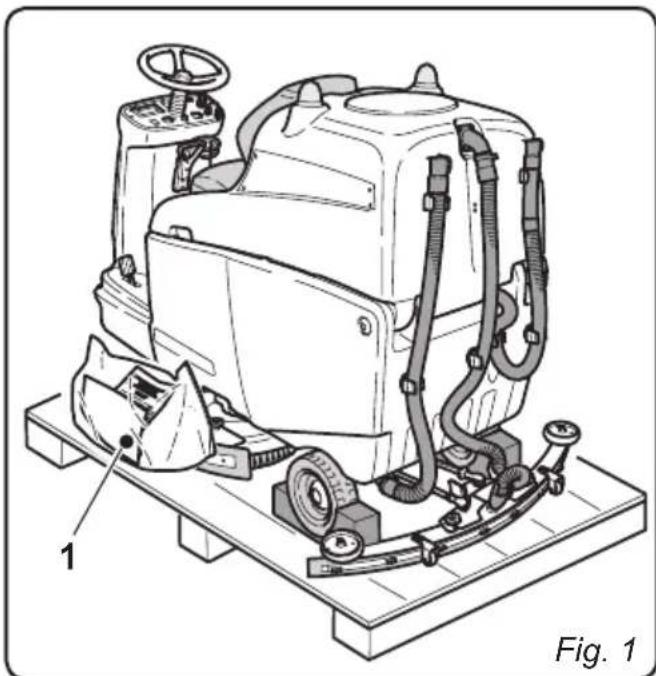
2.1 - UNPACKING (Fig. 1)
Once the packaging has been removed as shown in the instructions on the packaging itself, check that the machine and all the components supplied are intact.
If any evident damage is found, contact the area agent and the carrier within 3 days of receipt.
- Remove the pack (1) containing the accessories supplied.
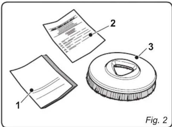
2.1.a - Standard machine equipment (Fig. 2)
The accessories supplied are as follows:
1) Machine use and maintenance manual.
2) Battery charger instruction manual (if present).
3) 2 brushes (machine mounted).

EN
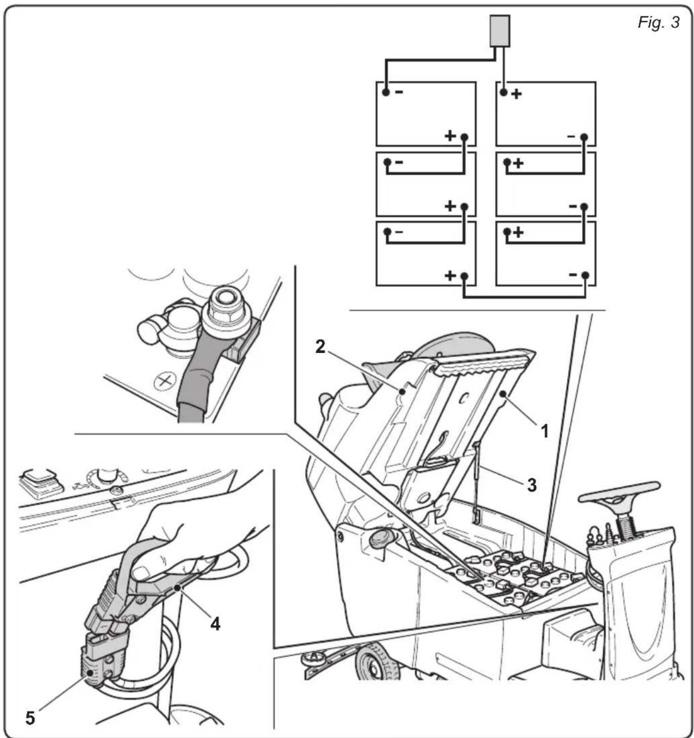
2.1.b - Battery installation (Fig. 3)
- Lift the recovery water tank (1) using the appropriate handles (2).
The tank will be kept open by the gas spring (3).
-
Position the batteries as shown in the diagram and connect them as shown in the electrical scheme below using the supplied cables and plugs.
-
Connect the plug for the batteries (4) to the socket (5).
- Lower the recovery water tank (1) assisting the downward movement.

NOTE:
The batteries must be installed and connected by qualified personnel.
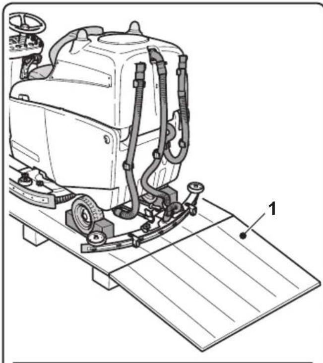
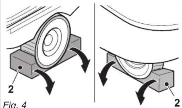
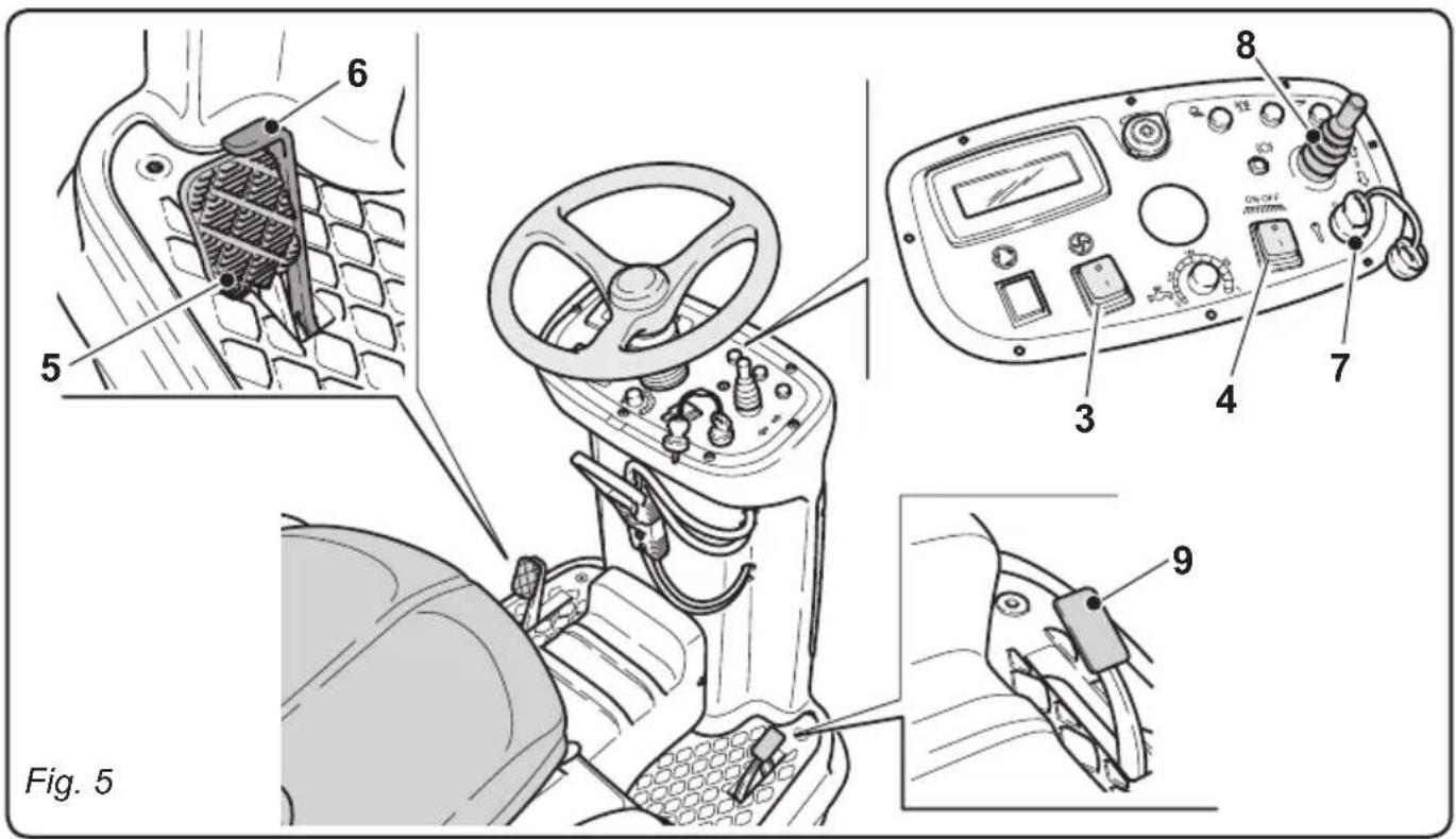
2.1.c - Unloading the machine from the wooden pallet (Fig. 4-5)
- Position a ramp (1) and fasten it to the wooden pallet.
- Remove the wooden blocks (2) from the three wheels.
- Sit on the seat in driving position.
- Check that the switches (3) and (4) are turned on the "0" position.
- Release the parking brake by pushing the locking device (6).
Keep the brake (5) engaged to avoid movements of the machine.
- Start the machine by turning the key (7) to the "1" position.
- Shift the movement direction selector (8) to “(forward) or “(reverse), then press the accelerator pedal (9) and drive down the pallet using the ramp.
3.1 - ASSEMBLY COMPONENTS
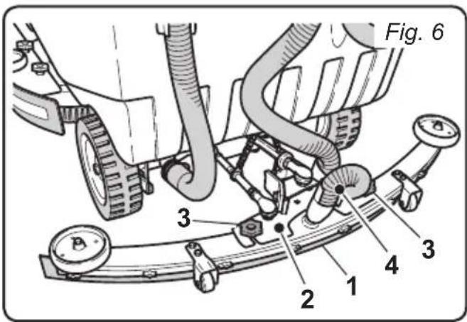
3.1.a - Squeegee installation (Fig.6)
-
Insert the squeezegee (1) into its support plate (2) and fasten it by tightening the two knobs (3).
-
Connect the suction tube (4) to the squeezee's intake opening.
4.1 - CHARGING THE BATTERY

DANGER:
Charge the batteries in well-ventilated areas which comply with standards in force in the country of use.
For safety-related information, follow what is described in chapter 1 of this manual.

WARNING:
For the information and warnings concerning the battery, refer to what is indicated in the battery charger's manual attached to this user and maintenance manual.

WARNING:
The machine comes pre-calibrated for function with gel batteries. If acid batteries are to be installed, please contact our Assistance Centre in order to re-calibrate the machine.
It is forbidden to use the machine with gel batteries if it has been calibrated for use with acid batteries.

NOTE:
For more information regarding machine calibration, see section 11.1.l.

NOTE:
10 hours are needed for complete battery charging. Avoid partial recharges.
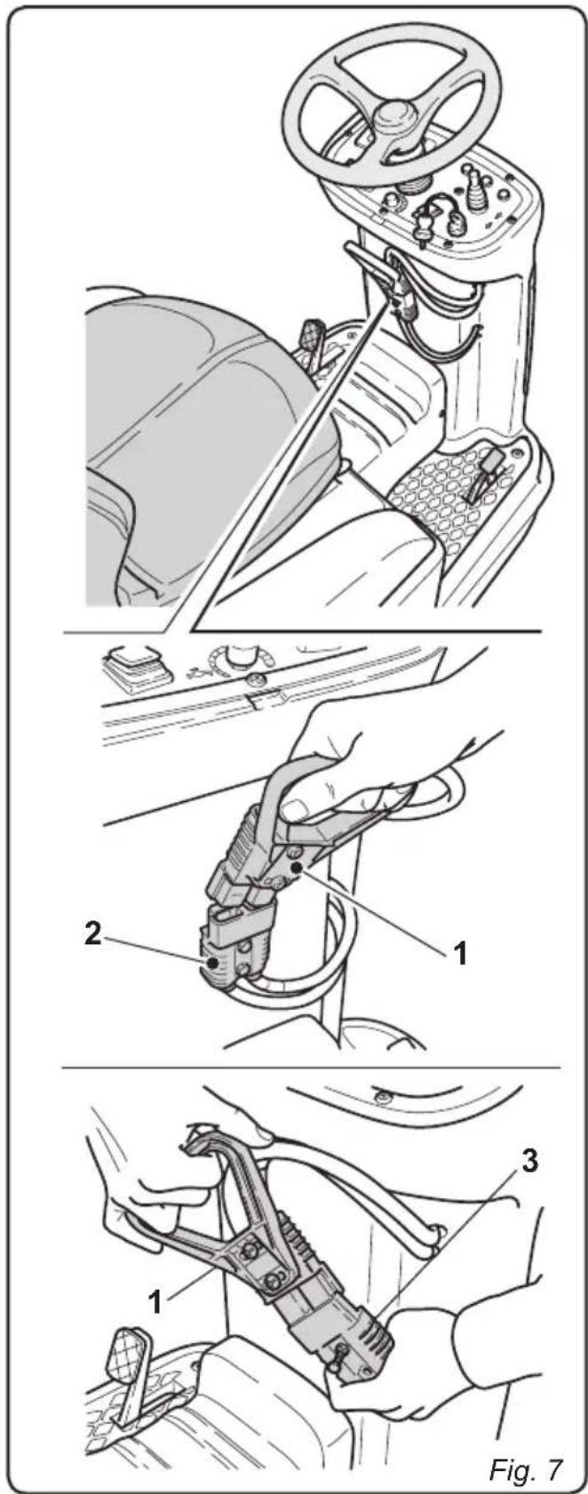
4.1.a - Charging the battery with an external battery charger (Fig.7)
- Move the machine near the battery charging station.
- Remove the battery plug (1) from the socket (2) of the machine's electrical system.
- Connect the battery plug (1) to the external battery charger's outlet (3).
- Once the batteries have been charged, reconnect the battery plug (1) to the socket (2) of the machine's electrical system.
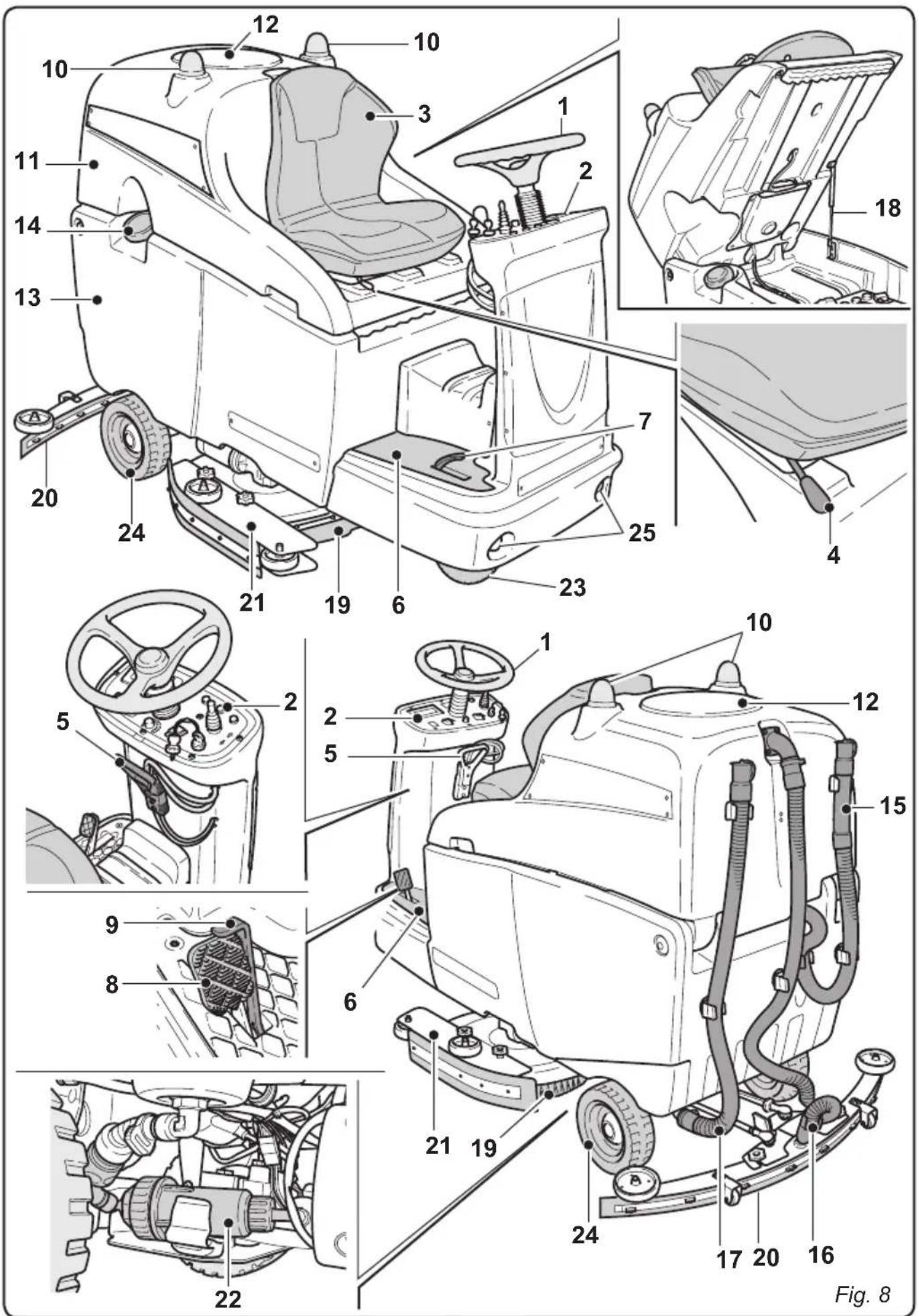
5.1 - GETTING TO KNOW THE MACHINE (Fig. 8)
1) Steering-wheel
2) Dashboard
3) Seat
4) Adjusting seat lever
5) Battery socket/plug
6) Foot rest
7) Accelerator pedal
8) Brake pedal
9) Parking brake lever
10) Flashing lights
11) Recovery water tank
12) Recovery water tank cover
13) Clean water tank
14) Clean water filling opening
15) Recovery water drain hose
16) Squeegee water aspiration hose
17) Clean water drain hose
18) Gas spring
19)Brushes unit
20) Squeegee
21) Side skirts
22) Water filter
23) Traction directional wheel
24) Rear wheels
25) Operating lights
6.1 MACHINE CONTROLS
6.1.a - Control panel (Fig. 9)
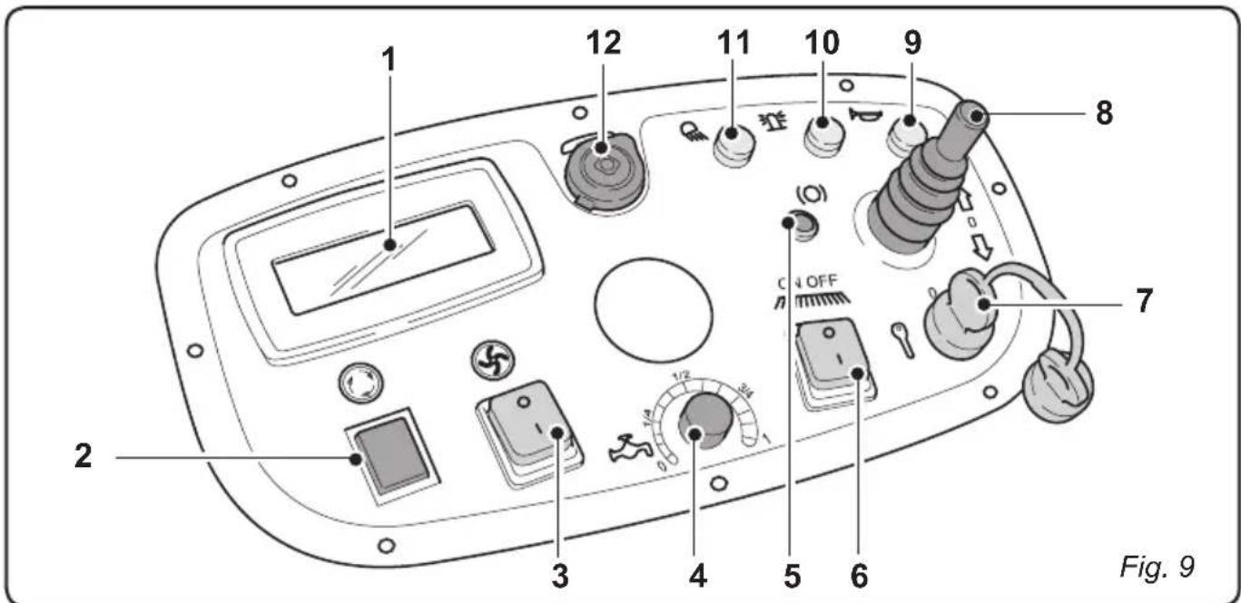
1) Display
- See paragraph ("Display controls")
2) Button not in use
3) Suction activation button (luminous)
- The suction activation is enabled by turning the key (7) to the "I" position.
- By putting the button (3) in the "I" position the suction will be activated, the symbol
on the display will be turned on and, if forward movement or neutral are enabled, the squeegee will be lowered.
- By putting the suction activation button in the "0" position the suction unit will be deactivated and the squeezegee will be raised.
4) Water flow adjuster - It allows to adjust the water flow.
If turned clockwise, the water flow increases gradually, if turned anti-clockwise, it decreases. - The water flow is activated only when the machine is moving forward.
5) Activated parking brake indicator (luminous)
-
The activation of the indicator is enabled by turning the key (7) to the "I" position.
-
The indicator turns on when the parking brake is engaged.
6) Brush unit button (ON/OFF)
-
The activation of the brush unit is enabled by turning the key (7) to the "I" position.
-
By putting the button (6) in the "I" position the brush unit will be lowered and the symbol on the display will turn on.
-
The brushes will turn when the machine moves forwards or backwards and they stop turning when the machine is not moving.
-
By putting the button in the "0" position the brushes will be stopped, the brush unit will be raised, and the symbol on the display will turn off.
7) Ignition key
-
Turned in a clockwise direction to "I", it powers the circuits, enabling machine operation.
-
Turned in an anti-clockwise direction to "0", it disconnects power to the circuits and can be removed.
8) Movement direction selector
-
It prepares the working of the machine.
-
By shifting the selector forward " the machine moves forward; by shifting the selector backward " the machine moves backward and the reverse acoustic signal is activated. When the selector is in the 0 central position the machine remains in neutral.
9) Acoustic warning button
- Press the button to produce an acoustic warning signal.
The activation of the acoustic warning signal is enabled by turning the key (7) to the "I" position.
10) Rotating flash lights button
- When pressed, with the key (7) in the "I" position, it starts the flash lights.
11) Operating lights button
- When pressed, with the key (7) in the "I" position, it turns on the operating lights.
12) 12V (1A) socket
-
12V (1A) socket.
-
The activation of the socket is enabled by turning the key (7) to the "I" position.
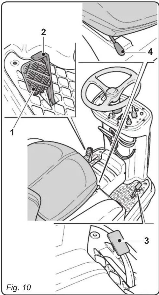
6.1.b - Toeboard controls (Fig. 10)
Brake pedal (1)
- When the brake pedal (1) is pressed, the machine slows down until it stops.
Parking brake lever (2)
- The parking brake must be activated every time the conductor steps off the machine.
- To engage the parking brake lever, press the brake pedal (1).
- To disengage the parking brake, press the small lever (2).
Accelerator pedal (3)
- By pressing the accelerator pedal, the machine moves forward or in reverse according to the position of the movement selector.
6.1.c - Seat adjustment (Fig. 10)

WARNING:
The adjustment of the seat must be done when the machine is not moving.
- The seat can be adjusted longitudinally: lift the adjusting lever (4) under the seat and shift the seat forward or backward.
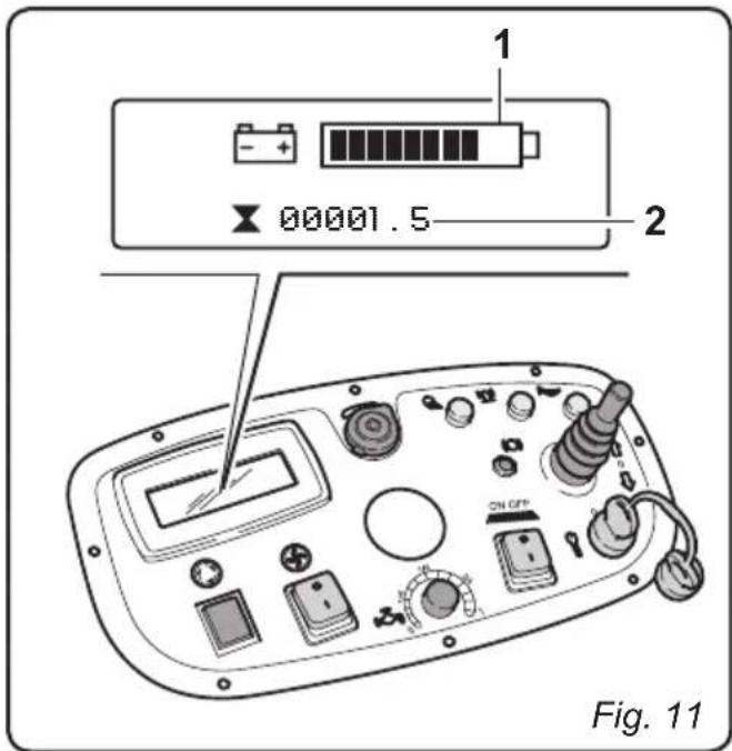
6.1.d - Display (Figs. 11-12-13)
The dashboard is equipped with a display which is lighted by turning the starter key to the "I" position.
The display will show:
Battery charge status
- A bar (1) on the screen displays the battery condition:
Charged battery: all the segments of the bar are displayed. While using the machine the length of the bar shortens gradually.
Discharged battery: only one segment of the bar is displayed and the battery symbol flashes.
Indicates that the batteries are completely drained; all of the operating functions will be deactivated, leaving only the drive function enabled.
Timer (2)
- Indicates the total working time of the machine.
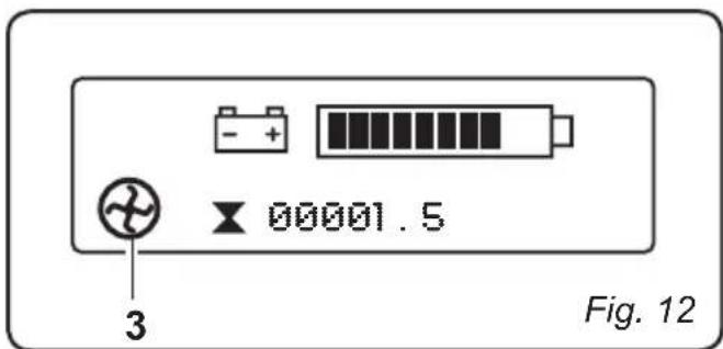
Suction unit symbol (3) (Fig. 12)
- The symbol is displayed when the suction unit is activated.
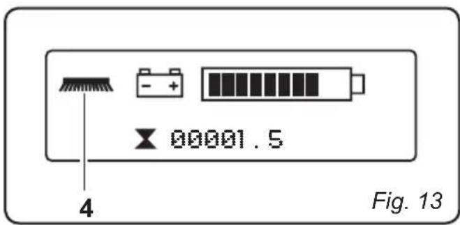
Brush unit symbol (4) (Fig. 13)
The symbol is displayed when the brushes are rotating.
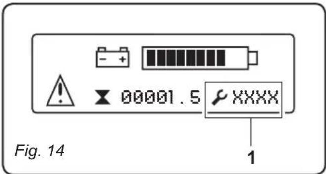
6.1.e - Alarms during function (Fig. 14)
In case of alarm while the machine is functioning, the symbol with an error co will appear on the display.
Here is a list of the possibleerror codes:
-1E03:
This code includes two kinds of error:
a) The buttons are not in the "0" position. Turn the ignition key to the "0" position, put all the buttons in the "0" position and start the machine again.
b) The recovery water tank is full.
It indicates that the level of liquid in the recovery water tank has reached the level of the alarm sensor; the suction unit deactivates. Move the machine to the discharge water station and drain the recovery water tank as indicated in the concerning paragraph.
-2F01:
The machine has been started while pressing the accelerator pedal.
Start the machine again without pressing the accelerator pedal.
- Battery flashing symbol:
Indicates that the batteries are completely drained; all operating functions will be deactivated, leaving only the drive function enabled.
Bring the machine immediately to the battery charging station.

NOTE:
If other error codes are displayed, contact the Authorized Assistance Service.
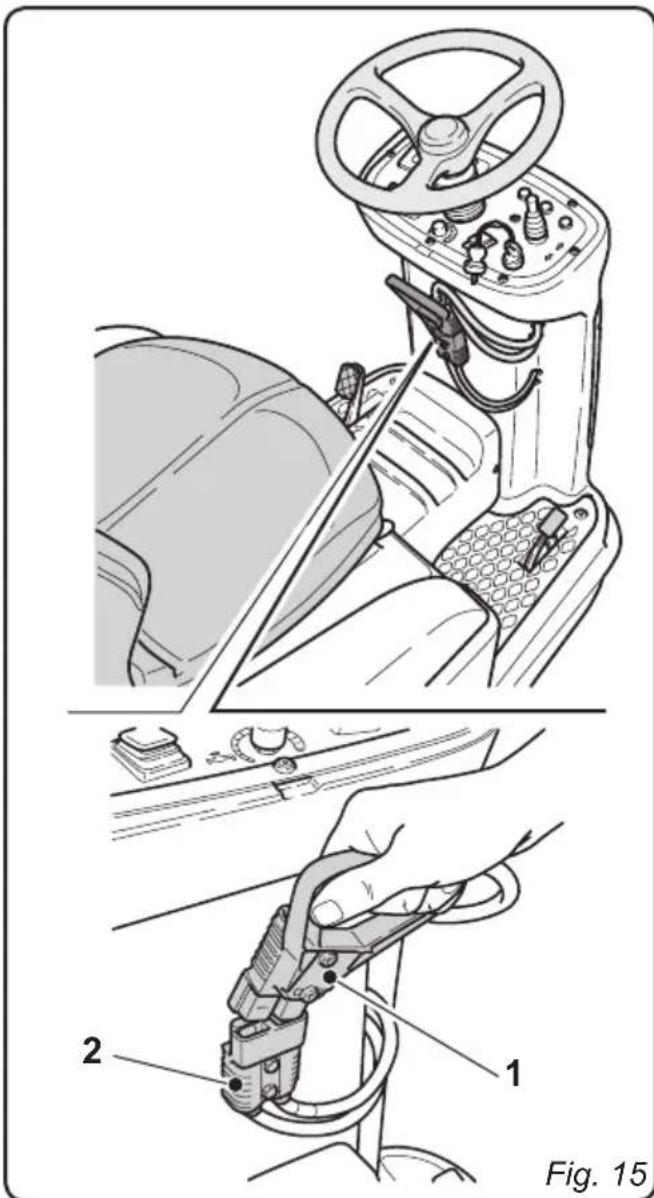
6.1.f - Emergency (Fig. 15)
In case of emergency pull the plug (1) out of the socket (2) to disconnect power to the circuits and to stop all the functions of the machine.

WARNING:
Unplug the machine while it is functioning only if absolutely necessary; do not follow this procedure to turn off the machine as it may cause serious damage to it.
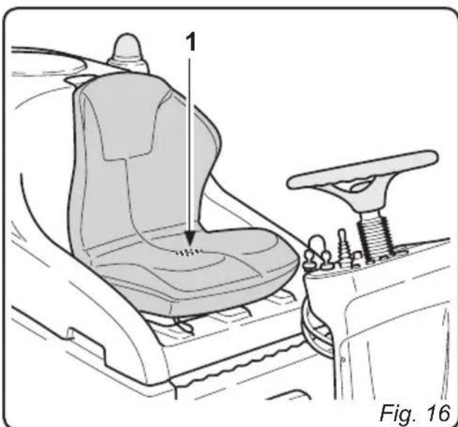
7.1 - SAFETY DEVICES

(Fig. 16)
WARNING:
The machine is equipped with an operator presence sensor (1); this sensor blocks all of the machine's functions and sets the machine in neutral whenever no operator is present in the driver's seat.
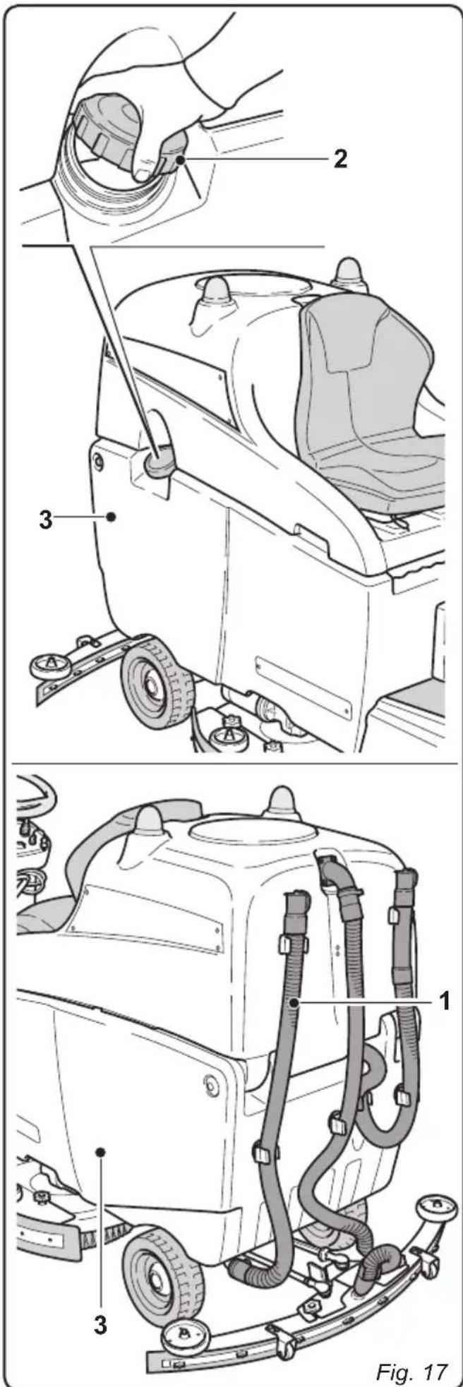
8.1 - FILLING THE TANK
(Fig. 17)

WARNING:
Only add clean mains water to the tank at a temperature no greater than 50^ .
- Check that the hose (1) is properly connected to the tank by means of the appropriate joints.
- Open the clean water tank (3) cap (2).
- Pour water into the tank (3) until it is full.
- Pour some liquid detergent into the tank according to the quantity of water in the tank.

NOTE:
Use non-foamy detergents only. For the quantities, follow the instructions provided by the detergent manufacturer according to the type of dirt.

DANGER:
- In the event of eye or skin contact with the detergent, or ingestion of the detergent, see the detergent manufacturer's usage and safety data sheet.
- Close the cap (2) when the filling procedure is completed.
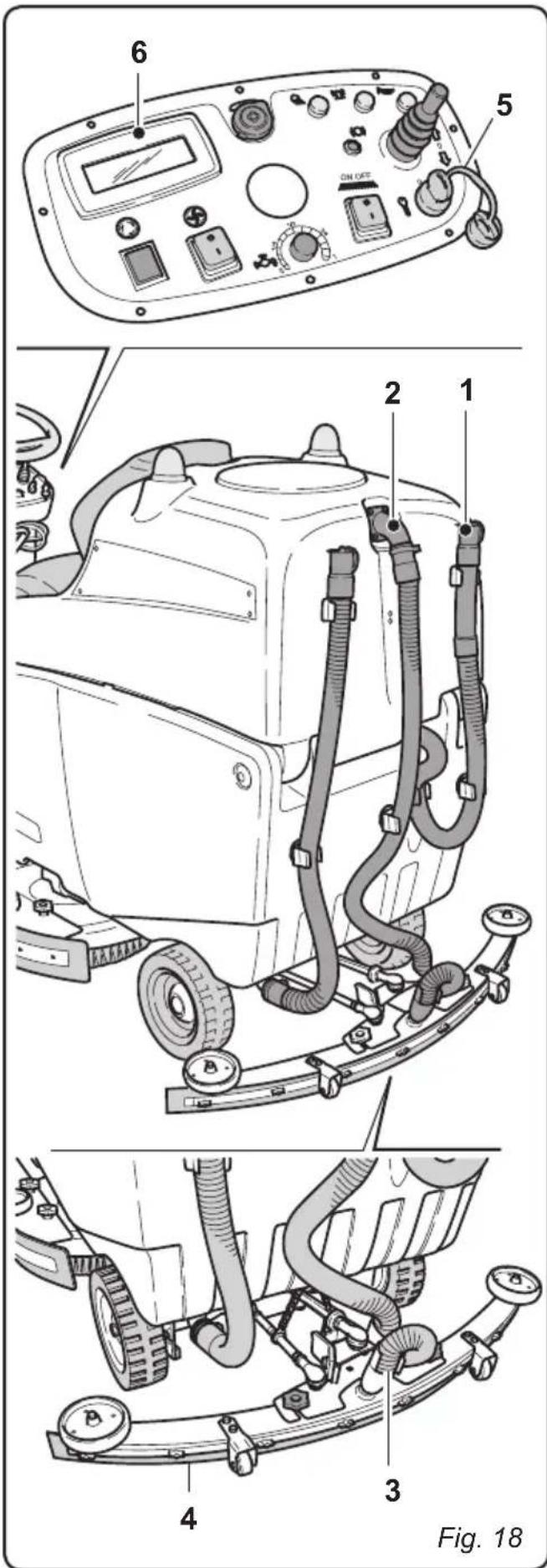
9.1 - OPERATION (Fig. 18)
9.1.a - Checks before use
- Check that the recovery tank's drainage tube (1) is properly connected and sealed.
- Check that the squeezegee's water suctioning tube (2) is properly inserted into the recovery tank.
- Check that the coupling (3) on the squeegee (4) is not obstructed and that the tube is properly connected.
- Check the charge status of the batteries by turning the key (5) to its "ON" position and checking the charge indication on the display (6).
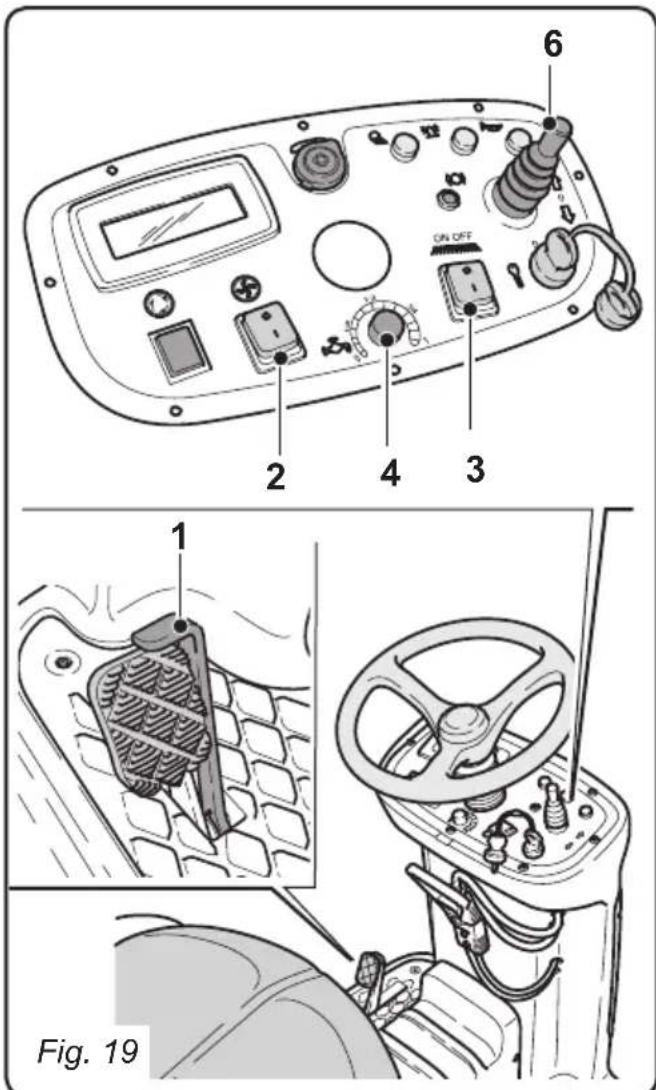
9.1.b - Preparing the machine and choosing the cycle (Fig. 19)
- Sit in the driver's seat and release the parking brake (1).
Working cycle:
- The machine can perform 4 working cycles:
Drying only cycle:
- To perform the drying cycle only, put the button (2) in the "I" position; the aspirator starts up.
Brushing only cycle:
- In order to perform the brushing cycle only, put the button (3) in the "1" position to prepare the rotation of the brushes; check that the water flow adjuster (4) is in the "0" position.
The brushes will rotate when the machine begins to move.
Washing, brushing cycle:
- Press the button (3) to set the machine to the rotation of the brushes and turn the water flow adjuster (4) to make the machine ready for the dispenser of water.
The brushes will begin to rotate and the machine will begin to dispense water (only with forward movement) once the machine begins to move.
Washing, brushing, drying cycle:
-
Turn the water flow adjuster (4) to make the machine ready for water dispenser;
-
Put the button (3) in the "I" position to set the machine to the rotation of the brushes; the brushes will rotate once the machine begins to move;
-
Put the button (2) in the "I" position to start the suction unit.
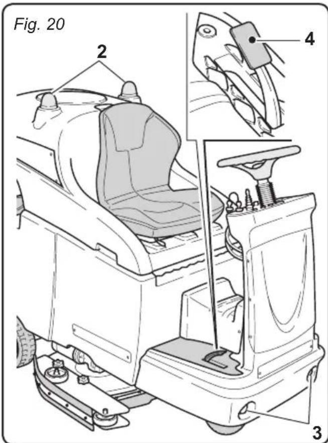
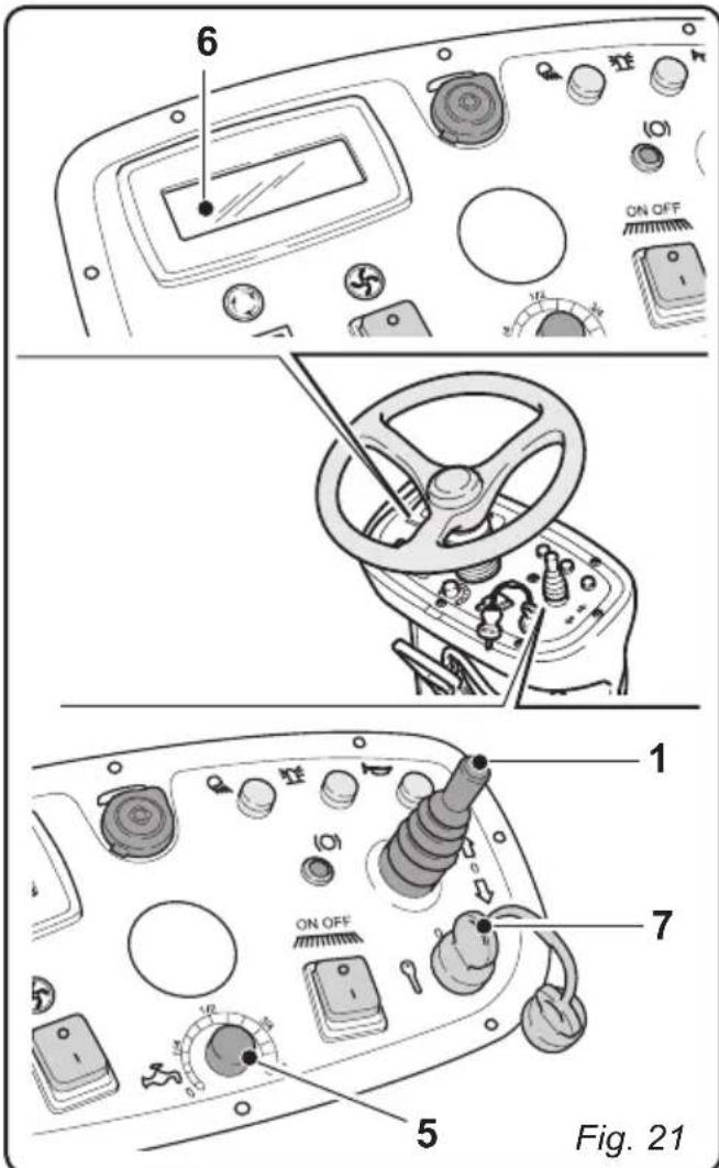
9.1.c - Using the machine (Figs. 20-21)

DANGER:
Be extremely careful when using the machine on ramps in order to avoid roll over or situations which may cause the machine to lose its balance.

DANGER:
Avoid sudden sharp turns. Turn the wheel from lock to lock only at low speed, always considering ground conditions.
After having started the machine and chosen the type of cycle, select the desired movement direction using the selector (1).
- Turn on the rotating flash lights (2) and the operating lights (3).
- Use the accelerator (4) to begin the cleaning operations.

NOTE:
Release the accelerator to stop the rotation of the brushes and the dispensing of water.

NOTE:
Proper floor cleaning and drying is performed by driving the machine forwards. When driving in reverse, the squeezegee is raised and the suction unit, for removing the water from the floor, is deactivated.
- If necessary, use the flow adjuster (5) to adjust the quantity of cleaning solution.
- Check the charge status of the batteries on the display (6).

DANGER:
When the operator gets off the machine, the machine goes into neutral. For this reason the parking brake MUST be engaged, as indicated in the "Toeboard controls" section.

DANGER:
It is forbidden to park the machine on ramps.
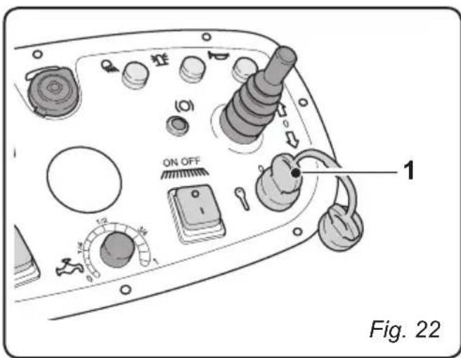
9.1.d - End of use and shutdown
(Fig. 22)
- Once all of the cleaning operations have been completed, shut off, in sequence, the rotation of the brushes and the suction unit, using the relative controls according to the type of cycle being employed.
- Turn the key (1) to its "0" position.
- Engage the parking brake as indicated in the "Toeboard controls" section.
- Empty and wash out the recovery tank and the solution tank as indicated in the relative sections.
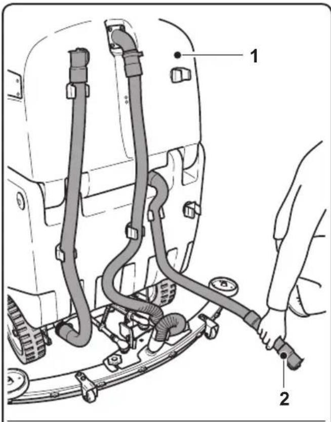
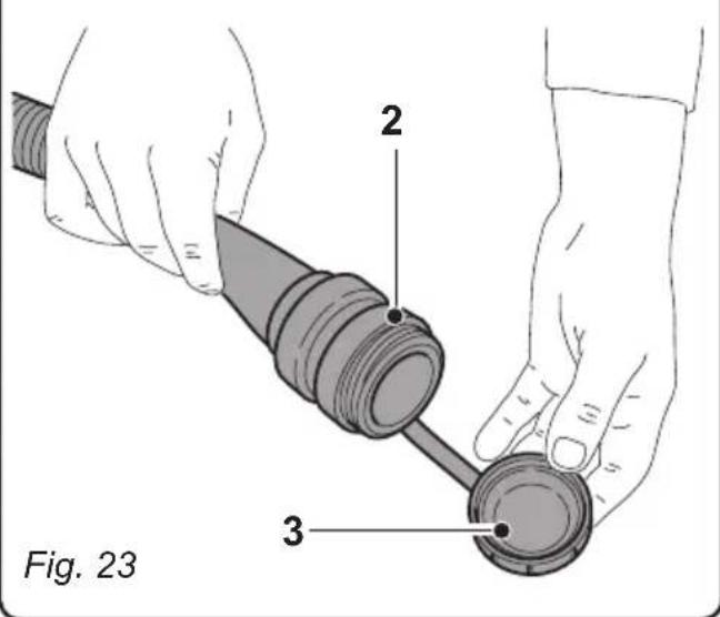
10.1 - DRAINING THE RECOVERY WATER
(Fig. 23)

DANGER:
Before lifting the recovery water tank (1) make sure it is empty.
At the end of the washing cycle or when the recovery water tank (1) is full, it is necessary to empty the tank by proceeding as follows:

N.B.:
To dispose of the recovery water, comply with the standards in force in the country in which the machine is used.
- Position the machine near to a drain outlet.
- Disconnect the hose (2) from the support.
- Remove the cap (3) from the hose (2) and drain all the water contained in the tank.

N.B.:
The amount of water that comes out can be modulated by pressing on the end of the tube (2).
Put the cap (3) back on the hose (2) and reposition it on the relative support.
11.1 MAINTENANCE AND CLEANING

WARNING:
For information and warnings regarding maintenance or cleaning, follow the information given in the "General warnings during maintenance" in chapter 1 in this manual.
OPERATIONS TO PERFORM DAILY
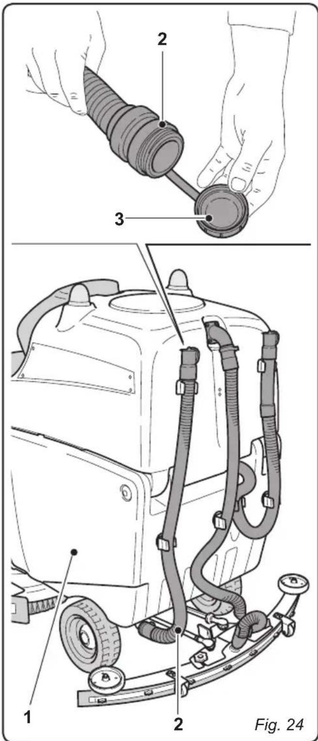
11.1.a - Emptying and cleaning the clean water tank (Fig. 24)

WARNING:
At the end of the washing operations, it is compulsory to drain and clean the clean water tank (1) to prevent deposits or scaling.
After draining the recovery water tank, drain the clean water tank (1) as follows:
- Position the machine over a drain outlet.
- Remove the hose (2) from the holding hooks and lay it down on the drain outlet; remove the cap (3) and drain all the water contained in the tank.
- Wash the inside of the tank, leaving the drain hose open and adding clean water through the top opening.
- Once finished cleaning, lift the tube (2), close it with its appropriate cap (3) and position it within its appropriate lodgings.
11.1.b - Cleaning the recovery water tank (Figs. 25-26)

WARNING:
At the end of the washing operations, it is compulsory to clean the recovery water tank to prevent deposits or scaling and the proliferation of bacteria, odours or mould.

DANGER:
Drain the recovery water tank (2) before lifting it.
- Remove the cover (1).
- Lift the recovery water tank (2).
- Leaving the hose (3) lowered and the cap off, add water through the upper opening (4), cleaning the inside of the tank until clean water comes out of the drain hose.
- Clean the level sensors (5) with a damp cloth, taking care not to damage them.
- Reassemble all of the parts by performing these operations in the opposite order.
- Unscrew the Allen screw (6) and remove the filter cover (7).
- Remove and clean the suction filter (8), removing any pieces of paper, wood, etc., which may be obstructing it.
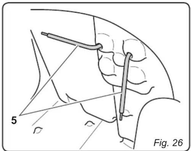
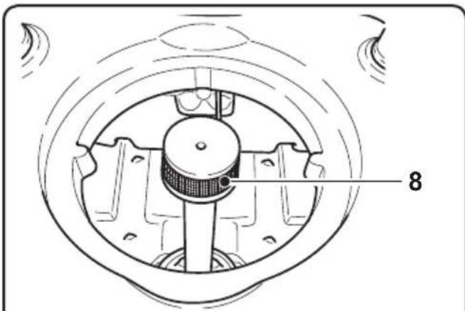
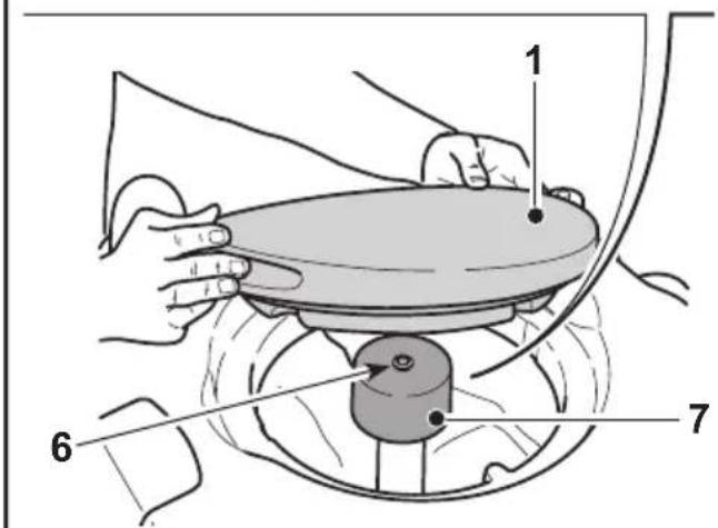
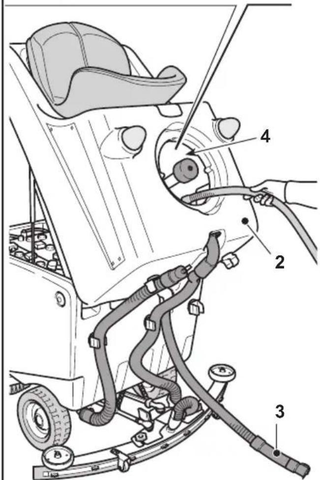
Fig. 25
11.1.c - Cleaning the wiper (Fig. 27)
In order to clean the squeegee correctly (2), it is necessary to remove it as follows:
- Disconnect the hose (1) from the squeegee (2).
- Loosen the knobs (3) and remove the squeegee (2).
- Wash the squeezegee and in particular the rubber blades (4) and the inside of the aspiration connector (5).

NOTE:
If, during washing, it is clear that the rubber blades (4) are damaged or worn, it is necessary to replace them or turn them over.
- Replace all the components in reverse order.
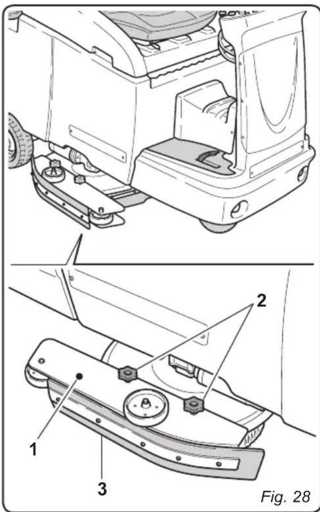
11.1.d - Cleaning the side skirts (Fig. 28)
In order to clean the side skirts (1) correctly, it is necessary to remove them as follows:
- Loosen the knobs (2) and remove the side skirts (1).
- Wash the rubbers (3).

NOTE:
If, during washing, it is clear that the rubber blades (3) are damaged or worn, it is necessary to replace them or turn them over.
- Replace all the components in reverse order.
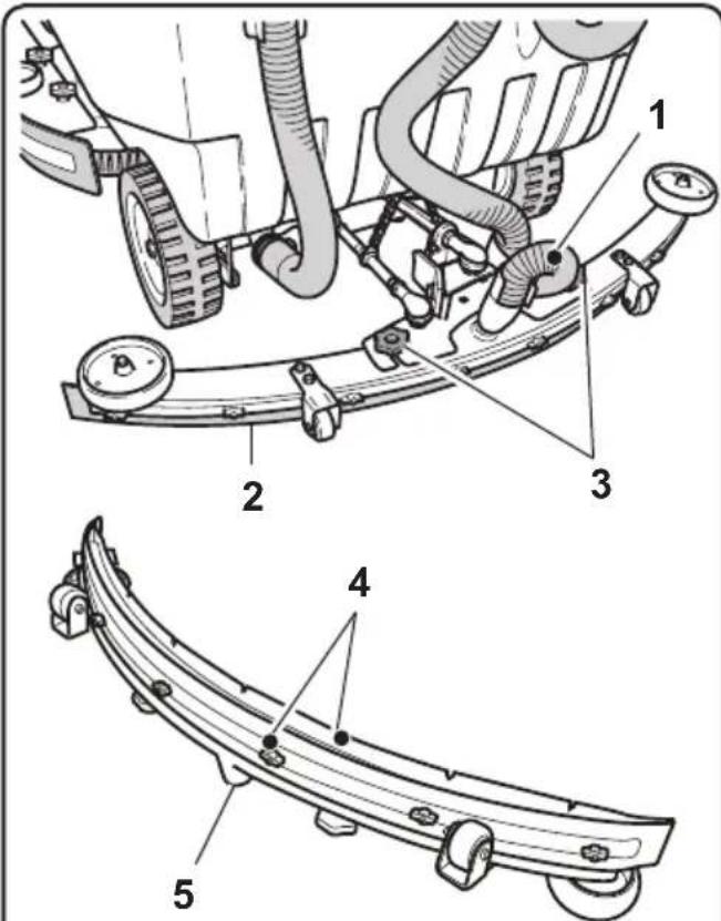
Fig. 27
OPERATIONS TO PERFORM WEEKLY
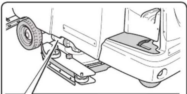
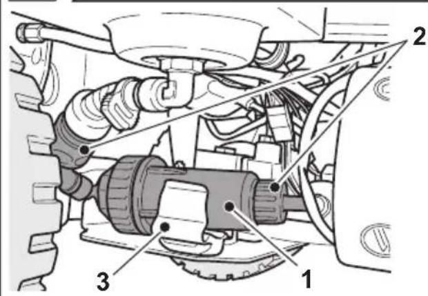
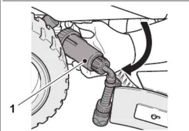
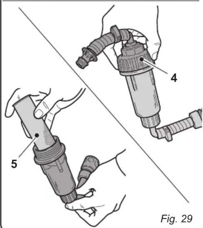
11.1.e - Cleaning the clean water filter (Fig. 29)
- Unhook the filter (1) from the fast release mounts (2) and remove it from the mount (3).
- Rotate the filter (1) to remove it from the machine.
- Remove the cap (4) and take out the filter cartridge (5).
- Clean the filter cartridge (5) using running water.
- Replace all the components in reverse order.
OPERATIONS TO BE PERFORMED EVERY 3 MONTHS
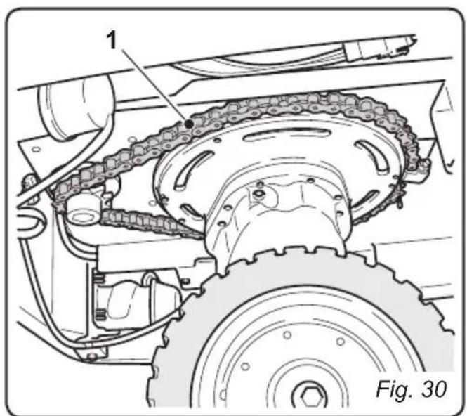
11.1.f - Check the wear status of the steering chain (Fig. 30)
- Check the wear and corrosion status of the chain (1) found beneath the machine near the front wheel.
If the chain appears corroded, it must be replaced.
Contact the technical assistance service.
OPERATIONS TO PERFORM WHEN NECESSARY
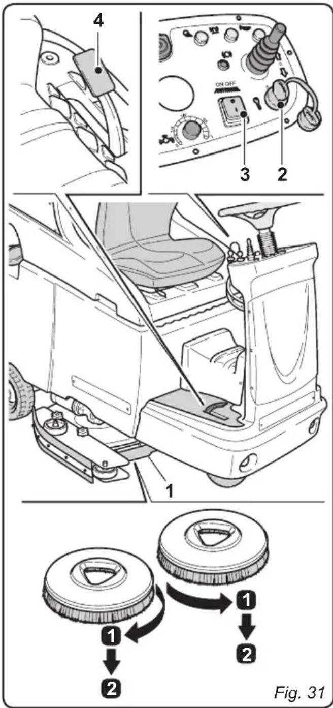
11.1.g - Replacing the brushes (Fig. 31)
The brushes must be replaced whenever they appear worn or whenever their bristles are shorter than 2cm . They must also be replaced based on the type of flooring to be cleaned; in order to replace them, perform the following operations:
- Insert a hand beneath the brush support unit (1). In order to detach the brush, turn it quickly and forcefully in the opposite direction from that in which it rotates during normal function.
- Place the new brushes beneath the brush support unit (1).
- Get into the driver's seat and turn the key (2) to its "I" position.
- Engage a movement direction.
- Press the (3) button to enable brush rotation; the brush unit will be lowered.
- By pressing the accelerator pedal (4), the brush support flanges begin to turn, thereby connecting with the brushes. Then, release the pedal.
- Press the (3) button again and turn the key (2) to its "0" position.
11.1.h - Replacing the squeezegee rubber blades (Fig. 32)
When it becomes clear that drying the floor is difficult or traces of water remain on the floor, it is necessary to check the wear on the squeegee rubber blades (1):
- Remove the squeegee unit (1) as indicated in the "Cleaning the squeegee" paragraph.
- Loosen the finned nuts (2) and remove the rubber blades (3).

NOTE:
When the rubber blades (3) are worn on one side, on one occasion they may be turned over.
- Replace or turn over the rubber blades (3) without inverting them.
- Replace all the components in reverse order.

NOTE:
Two types of rubber are available: Para rubber for all types of flooring and polyurethane rubber for workshop floors with oily residues.
11.1.i - Replacing the side skirt rubbers (Fig. 33)
When it becomes clear that the washing water is not well held by the side skirts, it is necessary to check the wear status of the rubbers (1):
- Remove the side skirts as indicated in the "Cleaning the side skirts" paragraph.
- Unscrew (2) and remove the rubbers (1).

NOTE:
When the rubber blades (2) are worn on one side, on one occasion they may be turned over.
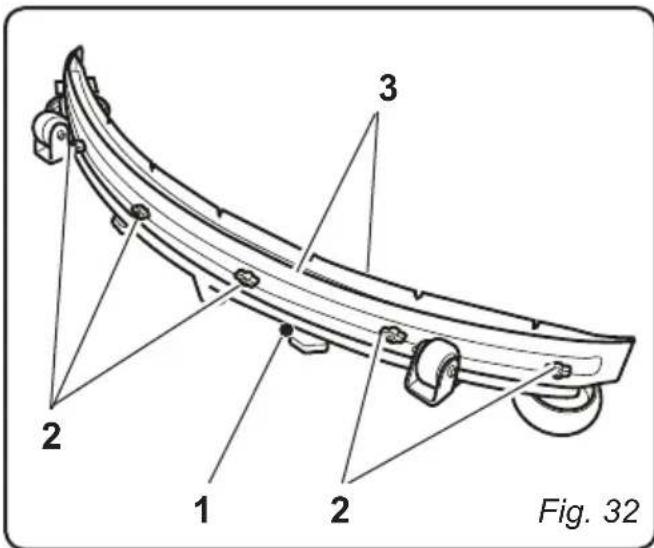
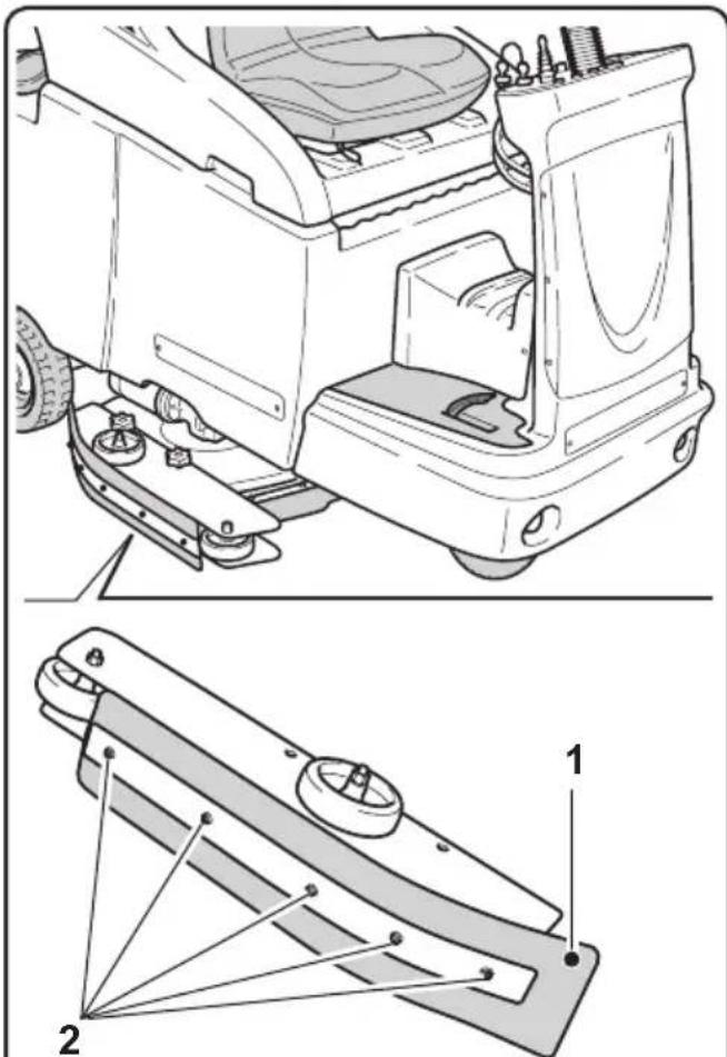
Fig. 33
- Replace or turn over the rubber blades (1) without inverting them.
- Replace all the components in reverse order.
11.1.j - Adjusting the pressure of the squeezegee (Fig. 34)
- Start up the machine and press the button.

The wiper unit will be lowered.
- Engage the machine's forward movement, move it a few metres, engage the parking brake and get off the machine.
- Use the threaded bar (1) to adjust the squeezees' (2) contact with the floor. Turn it clockwise for increased contact and counter clockwise for less contact.

NOTE:
When the squeegee is making proper contact with the floor, there will be no streaking on the floor during machine function and the entire length of the squeegee will be in contact with the floor.
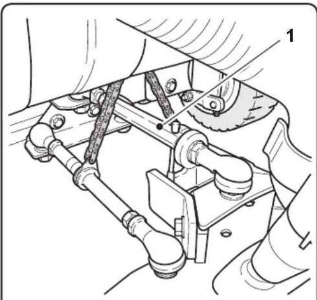
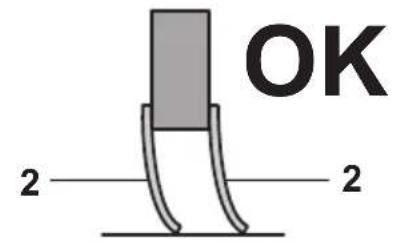
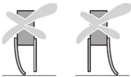
Fig. 34
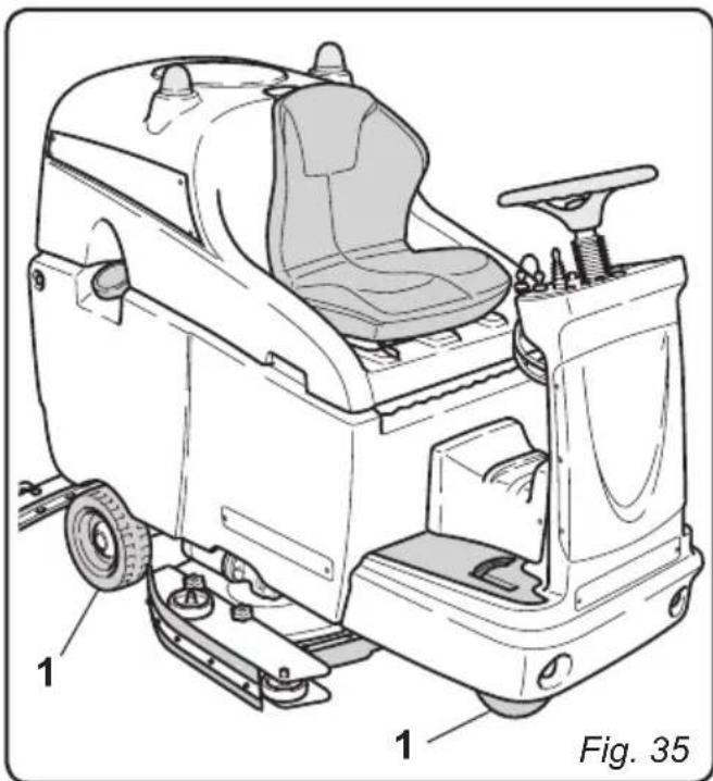
11.1.k - Checking the wear status of the three wheels (Fig. 35)
- Check the wear status of the three wheels (1) periodically; if they appear worn or damaged, contact a technical service centre in order to have them replaced.

DANGER:
Operating the machine with worn or damaged wheels poses a danger to the operator as the machine could have less traction when turning.
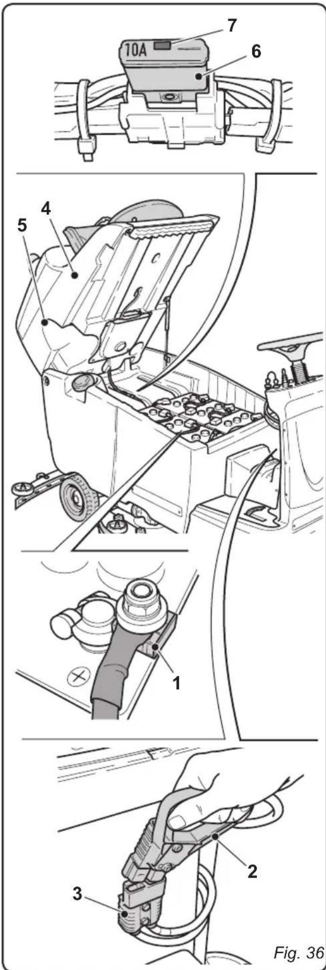
11.1.1 - Replacing the fuses (Fig. 36)

WARNING:
Replace the blown fuse with one with the same amperage.
- To change the fuse (1) on the positive pole of the battery, proceed as follows:

WARNING:
Make sure the recovery tank is empty.
- Pull the plug (2) out of the socket (3).
- Lift the recovery tank (4) using the specific handles (5).
Fuse (1) - 150A
Battery fuse.
Fuse (6) - 10A
[ \text{Dashboard fuse.} ]
- The fuse (6) can be restored and used again. To restore it, press the spline (7).
11.1.m - Battery charger configuration (Fig. 37)

WARNING:
The machine comes pre-configured use with "Sonnenschein" gel batteries.

DANGER:
This operation must be performed only by a qualified technician.
Standard configuration with Sonnenschin gel batteries
Take off the case (A) of the external battery charger and check that the switches (1 - 2 - 3 - 4) are set to the configuration shown in figure (B).
Perform the following operations to modify the configuration:
Configuration for gel batteries other than the Sonnenschein typology
- Check that the switches (1 - 2 - 3 - 4) are set to the configuration shown in figure (C).
Configuration for acid batteries
- Check that the switches (1 - 2 - 3 - 4) are set to the configuration shown in figure (D).

WARNING:
Only modify switches (1 - 2 - 3 - 4); do not alter the positions of switches (5 - 6 - 7 - 8).
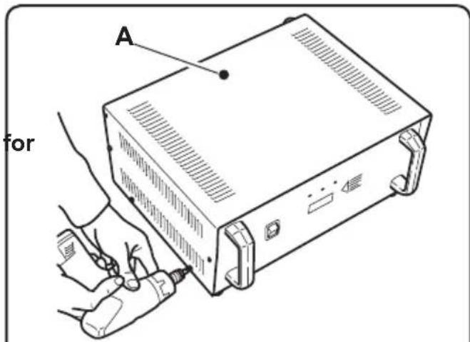
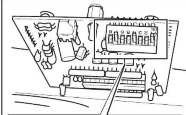
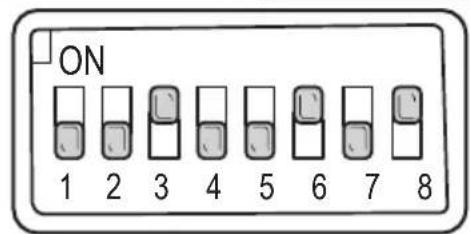
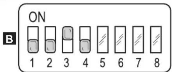
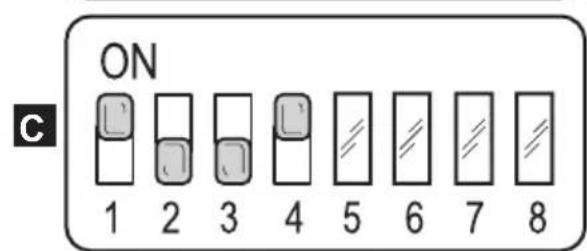
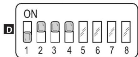
Fig. 37
TROUBLESHOOTING
| PROBLEM CAUSE SOLUTION | ||
| The machine does not start up when the key is turned. | Low battery. | Check that the battery is charged. |
| Main fuse blown. | Replace the fuse found on the battery cable. | |
| The brush doesn't turn. Movement set to neutral. Engage forward or reverse movement. | ||
| The suction unit does not function. | Recovery tank full. | Empty the tank. |
| Level sensors dirty. | Clean the recovery tank's level sensors with a damp cloth. | |
| The machine does dry properly, leaving traces of water on the floor. | Aspirator off. | Start up the aspirator. |
| Aspiration tube blocked. | Check and if necessary clean the aspiration tube that connects the squeezegee to the recovery tank. | |
| Recovery tank full. | Empty the recovery tank. | |
| Squeezegee rubber blades worn. | Replace or turn over the squeezegee rubber blades. | |
| No water comes out. | Tank empty. | Fill the tank. |
| Water flow adjuster is on “0”. | Turn water flow adjuster. | |
| Filter clogged. | Clean the filter. | |
| Pump solenoid valve not functioning. | Call technical assistance. | |
| PROBLEM CAUSE SOLUTION | ||
| The machine does not move in working conditions. | Operator not properly seated in the driver's seat. | Sit properly in the driver's seat. |
| Movement direction not engaged. | Use the appropriate control to engage the desired movement direction. | |
| Operator presence sensor malfunction. | Call customer service to request replacement. | |
| Insufficient floor cleaning. Unsuitable brushes or detergent. | Use brushes or detergents which are suitable for the type of floor or dirt to be cleaned. | |
| Brush worn. | Replace the brush. | |
WIRING DIAGRAM
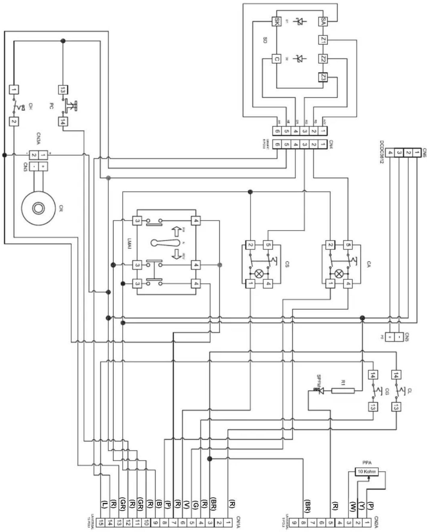
E112
E112 abbreviations
CA. Suction control
CG. Rotating flashlight control
CH Key
CL. Lights control
CN1 15 PIN connector
CN2A. .9 PIN connector
CN3. Buzzer connector
CN3A. Buzzer connector
CN4. Diode Card connector
CN5 ....Socket connector
CN6.......Transformer connector
CR. Reverse motion buzzer
CS. Brush control
D1 1N5819 diode
D2 1N5349 X3 diode
DCDC3612 36V-12V transformer
LMAI Forward/reverse gear lever
PC..... .electric horn button
PPA....Water pump potentiometer
R1. Resistance
SD. Diode card
SPFM. Handbrake pilot lamp
CN1A
- Headlights
- 24V
- Rotating flashlight
5 Suction - .Brushes
7....Small seat button - Antifoam
9 .0V
10..PIN3 pedal - +36V-key
- Electric horn
- V-F1
- P3-13
- 12V
Colours abbreviations
R. Red
BR. Brown
G.
Violet
P Pink
B Black
GR.. Grey
L.
Y
W. White
E112
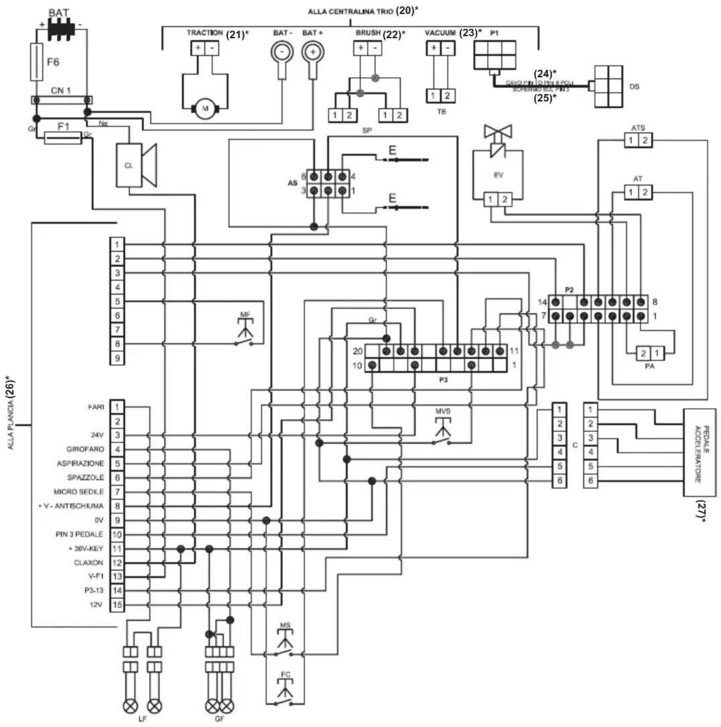
E112 abbreviations
AS. Antifoam
AT. Squeegee actuator
ATS. Brush actuator
BAT 36V Battery
C. Connector
CL. Electric horn
CN1 175 A Connector
DS. Display
E. Electrodes
EV. Solenoid valve
F1. 10A fuse
F6. 150A fuse
FC.....Lock of ATS downward movement
GF Rotating flashlight
LF. Headlights
M. Traction motor
MF. Small handbrake button
MS. Small seat button
MVS... ..Small turning speed button
P2. Triode control unit
P3. Triode control unit
PA. Water pump
SP .Brushes
TB Turbine
(A)* 1. Headlights
3. 24V
4. Rotating flashlight
5. Suction
6. .Brushes
7............Small seat button
8. Antifoam
9 0V
10 PIN 3 Pedal
11. +36V-Key
12. Electric horn
13. V-F1
14. P3-13
15. 12V
(20)* . At triode control unit
(21)* Traction
(22)* Brush
(23)* Suction unit
(24)* Pin to PIN 6 poles cable
(25)* Screen on PIN 3
(26)* .At dashboard
(27)* Accelerator pedal
Cher client,
1.1 INTRODUCTION FR-6
CG. Commande gyrophare
CH Clé
CL……Commande lumières
MF. Micro frein a main
MS. Micro siege
CN2A. Conector 9 PIN
CN3. Conector zumbador
CN3A. Conector zumbador
CN4. Conector ficha diodos
- Afrouxe os botões (2) e remove as saias laterais (1).
- Limpe as borrachas (3).

NOTA:
DIAGRAMA (ESQUEMA) ELETRICOS

E112
Abreviaceoes E112
CA.......Controle de Sucao
CG. Controle de farol giratorio
CH.
CL. Controle de luz
CN1. Conector 15 PIN
CN2A... Conector 9 PIN
CN3. Conector sonoro
CN3A.. Conector sonoro
CN4... Conector Placa diodo