S1 45D55 - Scrubber Ghibli - Free user manual and instructions
Find the device manual for free S1 45D55 Ghibli in PDF.
Frequently Asked Questions - S1 45D55 Ghibli
Questions des utilisateurs sur S1 45D55 Ghibli
0 question sur cet appareil. Repondez a celles que vous connaissez ou posez la votre.
Poser une nouvelle question sur cet appareil
Download the instructions for your Scrubber in PDF format for free! Find your manual S1 45D55 - Ghibli and take your electronic device back in hand. On this page are published all the documents necessary for the use of your device. S1 45D55 by Ghibli.
USER MANUAL S1 45D55 Ghibli
The machine identification data and the "CE" marking are shown on the plate (1), located under the control panel.
It is advisable to make a note of the machine model and the relative serial number shown on the following page.
FR
DONNÉES D'IDENTIFICATION
(Translation of original instructions)
FR
Francais FR-1
Thank you for choosing one of our cleaning products.
The floor scrubber dryer that you have purchased has been designed to satisfy the user in terms of ease of use and reliability over time.
We are aware that in order for a good product to stay that way, over time, it requires continuous updates aimed at meeting the expectations of those who use it on a daily basis. For this reason, we hope that you will not only be a satisfied customer but also a partner who does not hesitate to give us your opinions and ideas originating from your personal day-to-day experience.
Contents
Technical data EN-3
1.1 INTRODUCTION EN-5
1.1.a Purpose of the manual EN-5
1.1.b Consulting the manual EN-5
1.1.c Key to symbols used in the manual EN-5
1.1.d Conventional terminology EN-5
1.2 GENERALWARNINGS EN-5
1.2.a Personnel qualifications EN-5
1.2.bOperator position EN-5
1.2.c Protective clothing.. EN-6
1.2.d General warnings before use EN-6
1.2.e General warnings while using the machine EN-6
1.2.f General warnings about the batteries EN-6
1.2.g General warnings during maintenance EN-6
1.2.h General warnings in the event of a fire EN-6
1.2.i Prolonged machine standstill EN-6
1.3 INTENDED MACHINE USE EN-7
1.4 NON-INTENDED MACHINE USE EN-7
1.4.a Zone with risk of explosion EN-7
1.5 DEMOLISHING THE MACHINE EN-7
1.6 REFERENCE STANDARDS EN-7
2.1 UNPACKING EN-8
2.1.a Standard machine equipment EN-8
3.1 ASSEMBLING THE COMPONENTS EN-9
3.1.a Positioning of the handle.. EN-9
3.1.b Assembling the tank cover EN-9
3.1.c Installing and connecting the batteries.. EN-10
4.1 CHARGING THE BATTERY EN-11
4.1.a Charging the battery using the on board battery charger (if present) EN-11
4.1.b Charging the battery using an external battery charger EN-12
5.1 GETTING TO KNOW THE MACHINE EN-13
6.1 CONTROL PANEL EN-14
7.1 FILLING THE TANK. EN-16
8.1 OPERATION EN-17
8.1.a Checks before use EN-17
8.1.b Preparing the machine and choosing the cycle EN-18
8.1.c Using the machine EN-19
8.1.d End of use and switching off EN-19
8.1.e Maximum recovery tank water level alarm EN-20
8.1.f Probe height EN-20
8.1.g Alarms list (only for models with integrated drive mechanisms) ....EN-21
9.1 DRAINING THE RECOVERY WATER EN-23
10.1 MAINTENANCE AND CLEANING EN-24
10.1.a Emptying and cleaning the clean water tank .EN-24
10.1.b Cleaning the recovery water tank EN-25
10.1.c Cleaning the squeegee .EN-26
10.1.d Cleaning the clean water filter EN-26
10.1.e Replacing the brush EN-27
10.1.f Replacing the squeegee rubber blades .EN-28
10.1.g Replacing the fuses EN-29
10.1.h Battery charger and digital instrument configuration EN-30
TROUBLESHOOTING EN-32
WIRING DIAGRAMS EN-34
Technical data
| 45M45 45M55 45D55 45D60 | ||||
| Type of use Operator on ground | ||||
| Characteristics | ||||
| Power supply 24V battery | ||||
| Installed load 1080 W 1230 W 1430 W | ||||
| Forward movement Manual Electric forward and reverse | ||||
| Washing width 440 mm 550 mm 600 mm | ||||
| Drying width 750 mm 850 mm | ||||
| Theoretical hourly working capacity | 1550 m²/h 1900 m³/h | 2750 m²/h | 3000 m²/h | |
| Brushes | ||||
| Diameter / pad / number | 440 mm / 16" x 1 | 550 mm / 20" x 1 | 310 mm / 12" x 2 | |
| Motor power / number | 500 W x 1 | 350 W x 2 | ||
| Motor speed | 170 rpm | 190 rpm | ||
| Specific pressure | 30 gr / cm² | 25 gr / cm² | 50 gr / cm² | |
| Traction | ||||
| Motor power | -- | 150 W | ||
| Maximum forward speed | -- | 5,0 Km/h | ||
| Maximum gradient which can be overcome at full load | 2% | |||
| Aspiration | ||||
| Motor power | 570 W | |||
| Negative pressure | 130 / 1350 mbar/mmH₂O | |||
| Air flow rate | 32 l / sec | |||
| Noise level | 67 dB (A) | |||
| Tank | ||||
| Type | “Tank in tank” | |||
| Recirculation | No | |||
| Solution capacity | 65 l | |||
| Recovery capacity | 45 l | |||
| Dimensions | 1130 x 520 x 970 mm | 1170 x 540 x 970 mm | 1100 x 610 x 970 mm | |
| Noise levels 66 dB (A) 63,9 dB (A) | 66 dB (A) | |||
| Vibrations ISO 5349 0,93 m/s | 2 | 1,17 m/s2 | 1,23 m/s2 | |
| Weight | ||||
| Empty weight 90 kg 94 kg 96 kg 98 kg | kg | |||
| Weight with batteries 143 kg 147 kg 176 kg 178 kg | kg 176 kg 178 kg | |||
| Kerb weight 208 kg 212 kg 241 kg | 243 kg | |||
| Accessories | ||||
| 0.7ø PPL brush | 40.0002.00 | 40.0003.00 | 40.0001.00(x2) | |
| Brush spray guard | 39.0022.00 | 39.0023.00 | ||
| Front rubber wiper element | 39.0007.00 | 39.0002.00 | ||
| Rear rubber wiper element | 39.0008.00 | 39.0001.00 | ||
| Optional accessories | ||||
| 0.9ø PPL strong brush | 40.0102.00 | 40.0103.00 | 40.0101.00(x2) | |
| 1.2ø PPL strong brush | 40.0302.00 | 40.0303.00 | 40.0301.00(x2) | |
| 1.2ø grit 80 tynex brush | 40.0202.00 | 40.0203.00 | 40.0201.00(x2) | |
| Drive mechanism | 40.1002.00 | 40.1003.00 | 40.1001.00(x2) | |
| Front anti-oil rubberwiper element | 39.0037.00 | 39.0033.00 | ||
| Rear anti-oil rubber wiper element | 39.0050.00 | 39.0039.00 | ||
| Set of 2 GEL batteries | 18.0000.00 - 2x 12V - 79Ah(C20) | 18.0001.00 - 2x 12V - 120Ah(C20) | ||
| Battery charger unit | 22.0032.00 - 230V 50-60Hz / 24V 12A | |||
| Battery charger unit forthe U.S.A. | 22.0077.00 - 115V 50-60Hz / 24V 12A | |||
Batteries:
The use of gel batteries is recommended.
- Machines with drive mechanisms: Type GF 12 - 105 V / 120 Ah (C20) gel batteries.
- Machines without drive mechanisms: Type GF 12 - 79 V / 79 Ah (C20) gel batteries
1.1 INTRODUCTION
The manual is an integral part of the machine itself; it must therefore be stored carefully in a safe place which is accessible to all users (operators and personnel in charge of maintenance) for the entire machine life until demolition.
1.1.a - Purpose of the manual
The purpose of the manual is to provide the instructions necessary for putting into service, using and maintaining the machine with which it is enclosed.
It is advisable to read the instructions carefully and comply with the safety standards described in the manual to the letter.
The non-observation of these instructions/standards may cause damage to the machine and injury to the operator for which under no circumstances is the manufacturer responsible.
The safety information described in the manual supplements and DOES NOT REPLACE standards in force in the country in which the machine is used.
1.1.b - Consulting the manual
The manual is divided into chapters according to a logical order of knowledge and use of the machine.
For help with finding a specific topic, first consult the CONTENTS shown at the beginning of the manual.
1.1.c - Key to symbols used in the manual
In order to highlight information and procedures regarding safety, maintenance etc., the following symbols have been adopted in the manual:

DANGER:
Warns of a serious, even fatal danger for the safety of the operator and/or third persons.

WARNING:
Extremely important information in order to prevent serious damage to the machine and the environment in which it operates.

N.B.:
Additional information for correct machine operation or of a general nature.
1.1.d - Conventional terminology
The terms front, rear, forward, back, upper, lower, left and right refer to the operator in the working position with his/her hands on the guide handle.
To simplify, the brand name of the model has been replaced with "Machine".
1.2 GENERAL WARNINGS
Before putting into service, using and maintaining the machine, it is necessary for the persons involved (persons in charge and operators) to be trained regarding the operating procedures and safety standards shown in this manual.
Respect all the provisions contained in the manual and in any enclosed documentation.

DANGER:
It is forbidden for untrained personnel, children and disabled persons to use the machine.
1.2.a - Personnel qualifications
Operator
The term operator refers to a generic worker able to perform simple operations such as running the machine and carrying out the relative cleaning at the end of the working shift.
Electrical/mechanical maintenance technician
A technician qualified to operate on the machine in order to repair or replace parts which require the removal of the protective cover.
1.2.b - Operator position
While using the machine, the operator is position at the rear of the machine with his/her hands on the handle.
1.2.c - Protective clothing
- Use protective clothing as indicated in the standards in force in the country in which the machine is used.
1.2.d - General warnings before use
- Before using the machine, check that the fixed safety guards (covers) are always correctly secured in position.
1.2.e - General warnings while using the machine
- If the machine makes strange noises, stop it immediately and identify the cause.
- Do NOT abandon the machine on surfaces which slope by more than 2% .
- While using the machine, do not knock into shelving or cupboards.
- It is forbidden to use the machine outdoors or on public roads.
- If possible, use the machine in environments where no persons are present; in the present of unauthorised persons, warn them to move away before using the machine.
- Do not use the machine in environments with the presence of corrosive or salty substances.
- Do not use the machine in explosive environments (ATEX).
1.2.f - General warnings about the batteries
- Battery acid is corrosive: in case of contact with the skin, rinse thoroughly with water.
- Use suitable personal protective equipment to prevent contact with the skin (see applicable regulations in the country in which the machine is used).
- Do not inhale the vapour: it is dangerous.
- When charging the battery, mixtures of explosive gases could form, therefore the rooms in which the battery is charged must be well-ventilated and comply with any specific applicable regulations.
- It is forbidden to smoke and/or use naked
flames within a 2-metre radius of the battery during charging, in the charging area and during battery cooling after charging.
- Report any leaks of liquid from the battery: These are dangerous and highly polluting.
1.2.g - General warnings during maintenance
- Disconnect the batteries before carrying out maintenance or repairs.
- Do not rest tools and metal objects on the batteries; danger of short circuits.
- Do not use aggressive detergents, acid, lye etc. during cleaning and washing and take particular care with electrical parts.
- Do not wash the machine with direct or pressurised jets of water.
- When the machine must be lifted for any maintenance operations, it is necessary to work safely by placing fixed supports underneath it.
- Contact an authorised support centre for repairs and request ORIGINAL spare parts only.
1.2.h - General warnings in the event of a fire
- In the event of a fire, use approved powder extinguishers only; do NOT use water to put out the fire.
1.2.i - Prolonged machine standstill
- Place the machine under cover, sheltered from atmospheric agents in a place where the temperature is between 5^ and +40^ .
- Remove the ignition key.
- Drain the clean water contained in the tank.
- Charge the batteries and, once they are charged, disconnect them from the charger.
- Charge the batteries once a month.
1.3. INTENDED MACHINE USE
The machine has been designed and manufactured for washing and drying indoor floor surfaces.

DANGER:
Any other use releases the manufacturer from responsibility for damage or injury to persons and/or things and invalidates any warranty condition.
1.4 - NON-INTENDED MACHINE USE

WARNING:
The machine is not intended for outdoor use.

DANGER:
- do not wash floors with water hotter than 50^ ;
- do not use diesel/petrol or corrosive detergents to wash floors;
- do not wash or suck up corrosive, flammable and/or explosive liquids, even if diluted.
1.4.a - Zone with risk of explosion
It is strictly forbidden to use the machine in environments where there is a risk of explosion with the presence of flammable and explosive gases, vapours, liquids and powders.
1.5. DEMOLISHING THE MACHINE
In order to protect the environment, proceed in compliance with local standards in force. When the appliance can no longer be used or repaired, proceed with the separate disposal of its components.
Electrical equipment cannot be disposed of as urban waste and it is necessary to dispose of it separately as introduced by the special regulation regarding the disposal of waste originating from electrical equipment (Italian Legislative Decree no. 151 of 25/7/05 - 2002/96/EC - 2003/108/EC).
The electrical equipment is marked with a symbol showing a wheeled bin with a cross on it. The symbol indicates that the equipment was put on the market after 13 August 2005 and that it must be disposed of separately.
In consideration of the substances and materials contained, inadequate or abusive disposal of the equipment or its improper use may cause damage or injury to persons and the environment.
Disposal of electrical waste which does not respect the standards in force leads to the application of administrative sanctions and penalties.
1.6. REFERENCE STANDARDS
This machine has been built in compliance with the machine directive in force and in accordance with the standards contained in the EC Declaration of Conformity supplied with the machine.
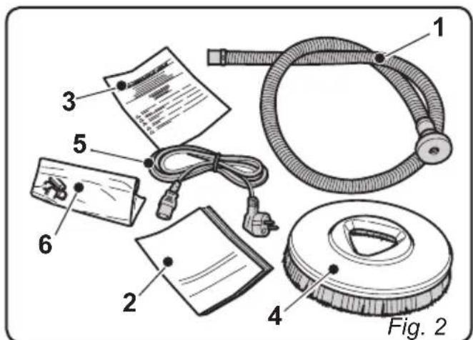
2.1 UNPACKING (Fig. 1)
Once the packaging has been removed as shown in the instructions on the packaging itself, check that the machine and all the components supplied are intact.
If any evident damage is found, contact the area agent and the carrier within 3 days of receipt.
- Remove the bag (1) containing the accessories.
- Cut the strap (2).
- Remove the recovery water tank cover (3).
- Remove the wooden blocks (4 and 5).
- Lift up the brush (6), by pressing the pedal (7) (see relative paragraph).
- Lift up the squeegee (8), by raising the handle (9) (see relative paragraph).
- Position a chute and unload the machine from the bench.
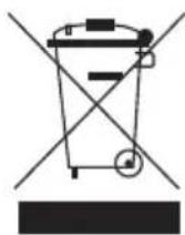
2.1.a - Standard machine equipment (Fig. 2)
The accessories supplied are as follows:
1) Water filling hose.
2) Machine use and maintenance manual.
3) Battery charger instruction manual (if present).
4) Brush/brushes.
5) Battery charger power cable (if present).
6) 7,5A fuse - 30A fuse - 40A fuse.
3.1 ASSEMBLING THE COMPONENTS
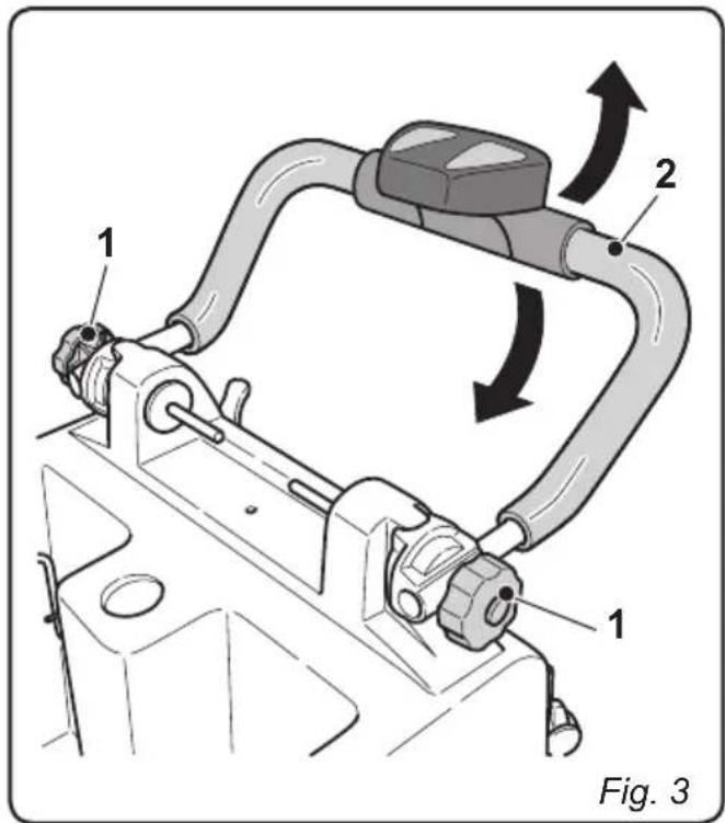
3.1.a - Positioning of the handle (Fig. 3)
- Loosen the handwheels (1).
- Position the handle (2) at the required height then tighten the handwheels (1).
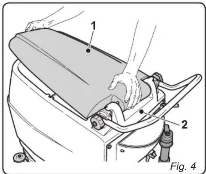
3.1.b - Assembling the tank cover (Fig. 4)
- Assemble the cover (1) as shown in the figure, inserting the cover slots onto the handle support pins (2).
- Exert pressure on the cover hinge (1) until it is correctly coupled.
EN
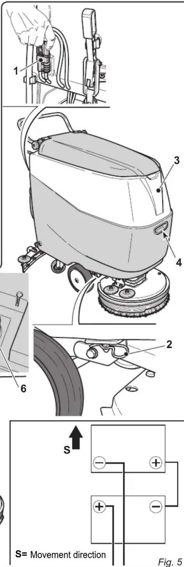
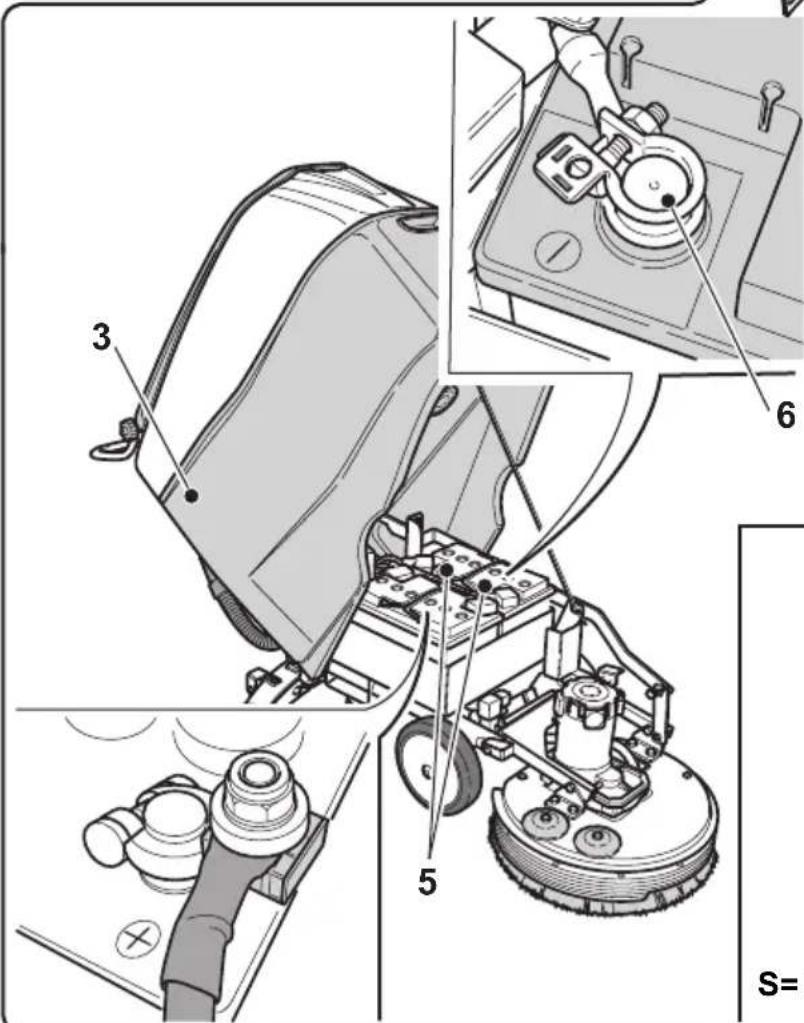
3.1.c - Installing and connecting the batteries (Fig. 5)

WARNING:
Check that the recovery tank and the clean water tank are empty.
- Disconnect the plug (1).
- Remove the split pin (2) and lift up the tanks (3), using the handle (4) until they are completely overturned.
- Position the batteries (5) as shown in the figure and connect them as shown on the chart in Fig. 5 using the cables supplied.
- Tighten the terminals (6) using an insulated wrench.
- Lower the tanks (3) and reposition the split pin (2).
- Connect the plug (1).

N.B.:
The battery must be connected by specialised personnel.
4.1 CHARGING THE BATTERY

DANGER:
Charge the batteries in rooms which are well-ventilated and comply with applicable regulations in the country of use. For safety-related information, follow what is described in chapter 1 of this manual.

WARNING:
For information and warnings about the battery and on board battery charger (if present) follow what is described in the battery charger manual enclosed with this document.

WARNING:
When the machine leaves the factory, it is calibrated to operate with gel batteries. If acid batteries are installed, it is necessary to contact the Support Centre to carry out new calibration.
It is forbidden to use the machine with gel batteries if the machine is calibrated for use with acid batteries.

N.B.:
For further information about calibration, please refer to the information in paragraph 10.1.h.

N.B.:
10 hours are needed for complete battery charging. Avoid partial recharges.
4.1.a - Charging the battery using the on board battery charger (if present) (Fig. 6)
- Move the machine close to a mains electricity socket.
- Remove the battery plug (1) from the system socket (2).
- Connect the battery plug (1) to the on board battery charger (4) socket (3).
- Extract the cable (5) from its special lodging and connect it to the socket on the machine (6). Connect the other end of the cable to an electrical outlet.
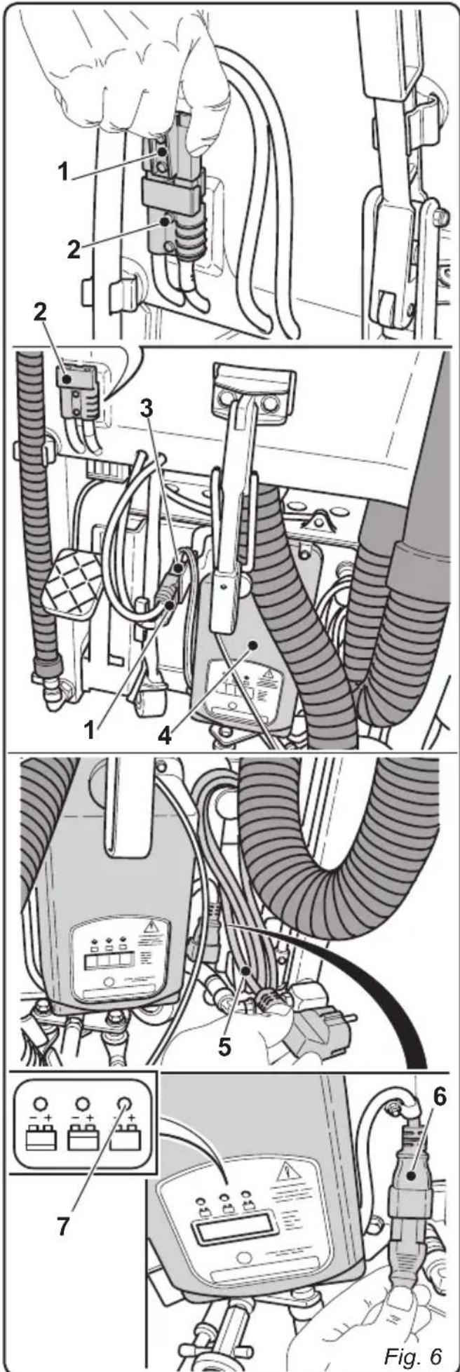

WARNING:
Make sure that the mains electrical voltage is compatible with the battery charger's operating voltage (230 Vac for the European market; 115 Vac for the American market; 50 / 60Hz ).
- Leave the batteries to charge until the "Green" LED (7) lights up, then remove the power cable (5) and put it away.
- Reconnect the battery plug (1) to the system socket (2).
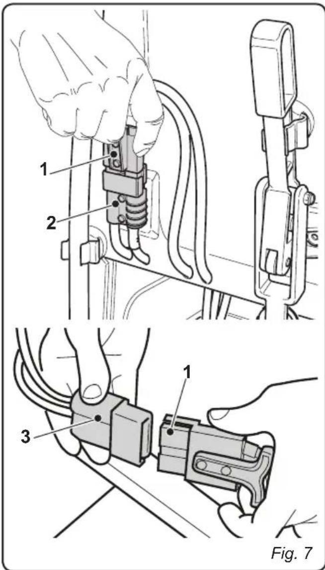
4.1.b - Charging the battery using an external battery charger (Fig. 7)
- Move the machine close to the battery charging station.
- Remove the battery plug (1) from the system socket (2).
- Connect the battery plug (1) to the external battery charger socket (3).
- Once battery charging is complete, reconnect the battery plug (1) to the system socket (2).
5.1 GETTING TO KNOW THE MACHINE (Fig. 8)
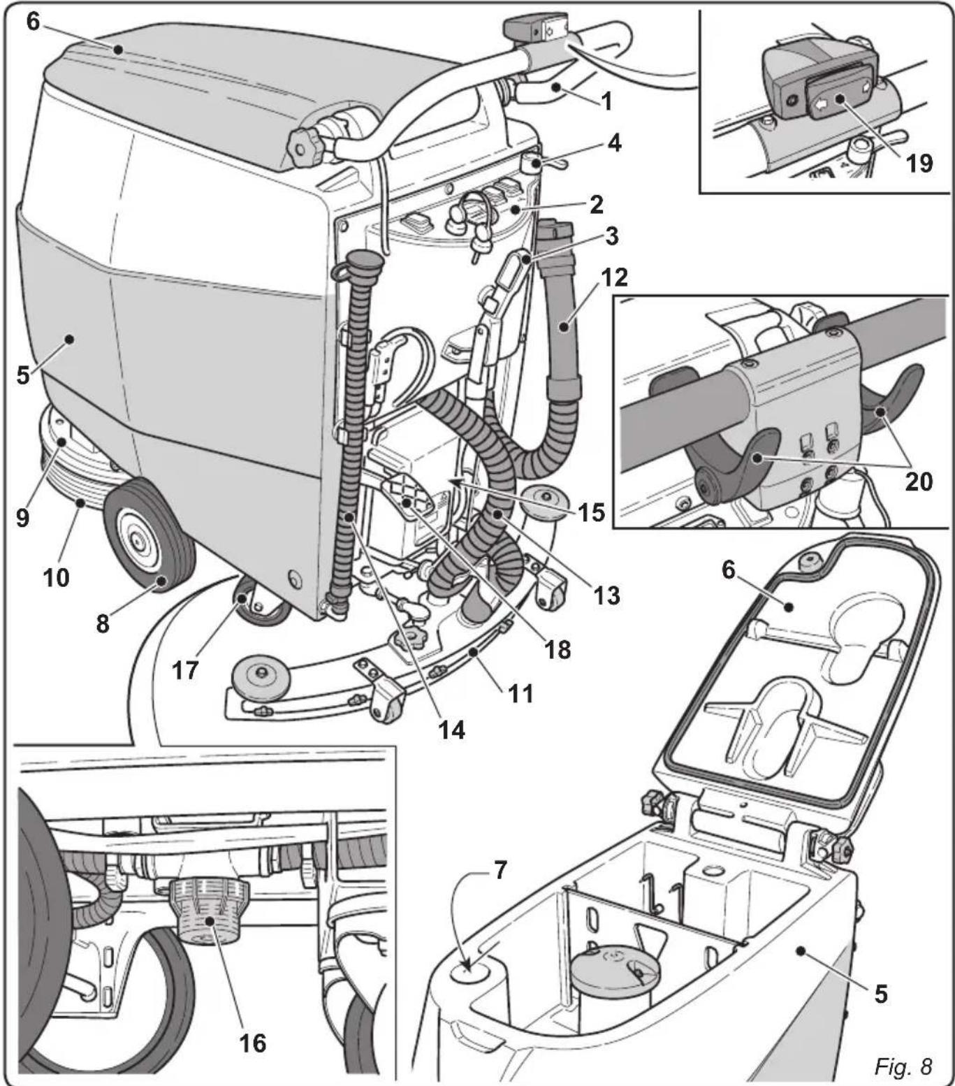
1) Guide handle.
2) Control console.
3) Squeezegee activation lever.
4) Water supply tap.
5) Tank.
6) Tank cover.
7) Clean water filling opening.
8) Wheels.
9) Brush rotation flange.
10) Brush.
11) Squeegee.
12) Recovery water drain hose.
13) Squeegee water aspiration hose.
14) Clean water drain hose.
15) Battery charger (optional).
16) Water filter.
17) Pivoting wheels.
18) Brush up/down pedal.
19) Brush rotation activation button.
20) Drive mechanism and brush rotation activation levers.
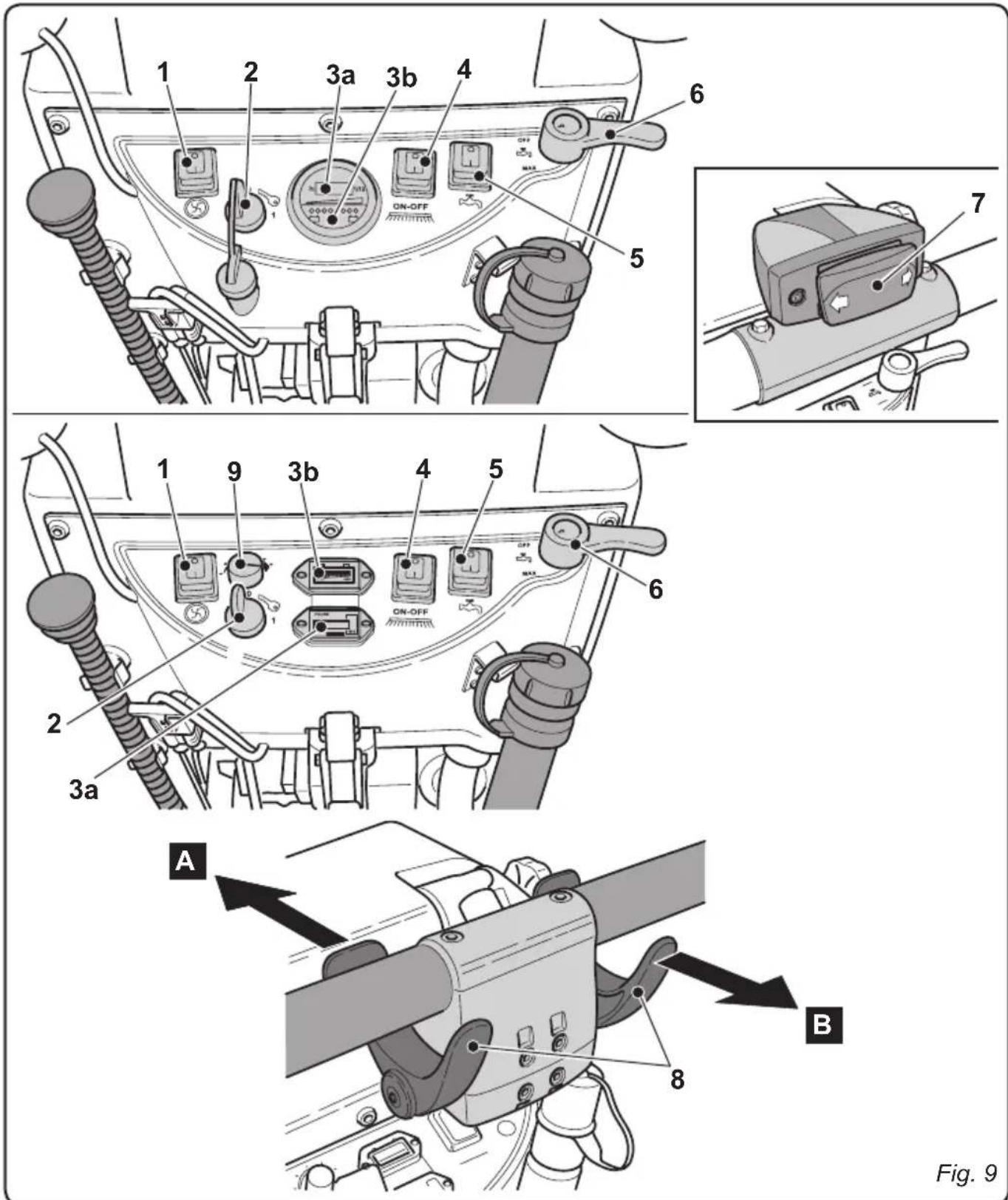
6.1 CONTROL PANEL (Fig. 9)
1) Suction unit activation switch
This switch can be enabled by turning the key (2) to its "1" position.
With the switch in its "I" position, press it down. The switch will light up and the suction unit will activate.
2) Starter key
Turn the key to its "1" position to enable the machine for function.
3a) Operating time indicator.
This indicator lights up while the key is in its "1" position and indicates the machine's working hours.
3b) Battery charge status indicator.
This indicator lights up while the key is in its "1" position and indicates the battery charge status.
Maximum battery charge status is indicated by the illumination of the green led indicators or the illumination of the single led indicator located on the far right of the instrument.
Medium battery charge status is indicated by the illumination of the orange led indicators or the illumination of the led indicators at the centre of the instrument.
- Minimum battery charge status is indicated by the illumination of the red led indicators.

N.B.:
Do not use the machine when the led indicator(s) are lit. Bring it to the battery charging station as soon as possible.
4) Brush rotation enabling switch
This switch can be enabled by turning the key (2) to its "1" position.
Press the switch down to enable the rotation of the brushes; the brushes are con
trolled by means of buttons (7) or (8), or else by means of the levers (9), based on the model. The button lights up when the brushes are rotating.
5) Water solenoid valve switch
This switch can be enabled by turning the key (2) to its "1" position and the switch (4) to its "1" position.
Press the switch (5) to enable the water solenoid valve for opening. The solenoid valve itself is controlled by means of buttons (7) or (8), or else by means of the levers (9), based on the model. The button lights up when the solenoid valve is open.
Use the tap (6) to adjust the quantity of water.
6) Water quantity adjustment tap
- Turn the tap (6) counter-clockwise to increase the quantity of water or turn it clockwise to decrease it.
7) Brush rotation activation button
With the key (2) in its "1" position and the switch (4) in its "l" position, press this button to activate brush rotation and water dispensing.
8) Drive mechanism and brush rotation activation levers
With the key (2) in its "1" position and the switch (4) in its "I" position, these levers (9) activate the drive mechanism, brush rotation and water dispensing.
Press the levers in direction "A" to activate forward movement; press the levers in direction "B" to activate reverse movement.

N.B.:
The speed of the movement is proportional to the angle at which the levers are pressed.
9) Maximum speed adjustment handle
Turn the handle to the left to decrease the maximum speed and turn it to the right to increase it.
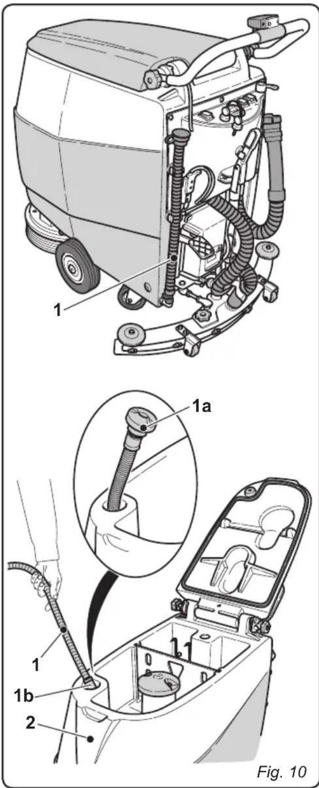
7.1 FILLING THE TANK (Fig. 10)

WARNING:
Only add clean mains water to the tank at a temperature no greater than 50^ .
- Remove the hose (1) supplied, connect one end (1a) to a tap and insert the other end (1b) in the tank (2).
- Turn on the tap and fill the tank (2).
- The tank's water level is indicated by the red ball in the transparent tube (1).
- Pour the liquid detergent into the tank.

N.B.:
Use non-foamy detergents only. For the quantities, follow the instructions provided by the detergent manufacturer according to the type of dirt.

DANGER:
If the detergent comes in contact with the eyes and/or skin or if swallowed, refer to the use and safety information booklet provided by the manufacturer of the detergent.
- When finished filling the tank: Insert the tube (1) completely into the tank (2). The end of the tube (1a) acts as a cap.
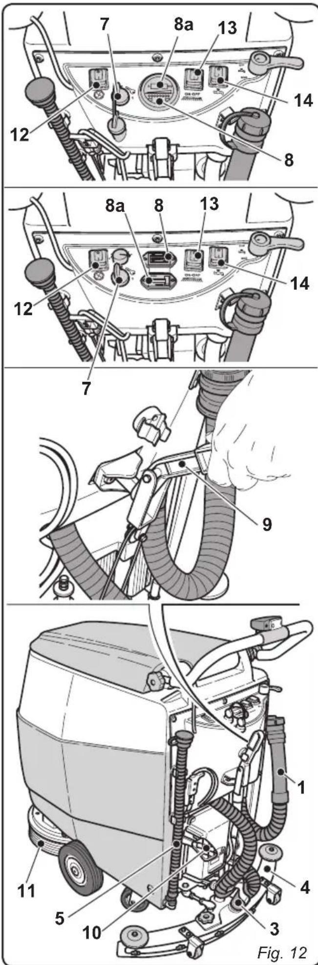
8.1 OPERATION (Figs. 11-12-13)
8.1.a - Checks before use
- Check that the exhaust tube (1) of the recovery tank is properly coupled and properly sealed.
- Check that the connector (3) on the squeezegee (4) is not blocked and that the hose is connected correctly.
- Make sure that the clean water drainage tube (5) is plugged and is properly connected to its appropriate supports.
- Turn the key (7) to its "1" position and use the led indicators (8) to check the battery charge level.
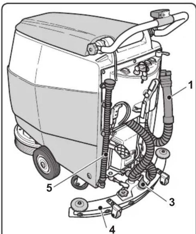
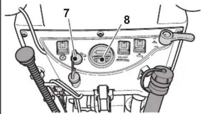
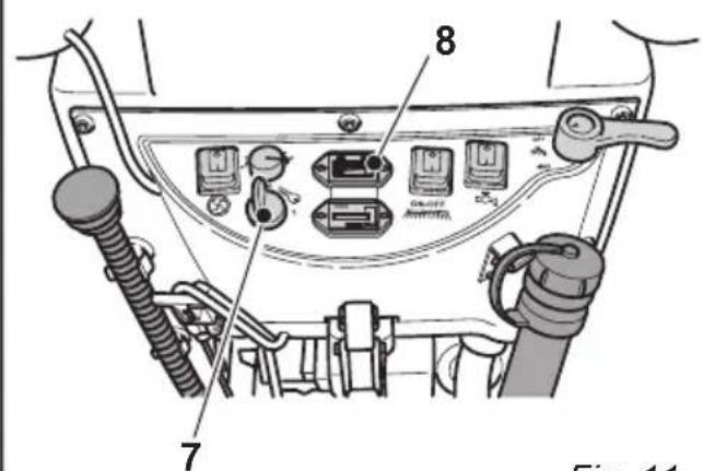
Fig. 11
8.1.b - Preparing the machine and choosing the cycle
- Turn the key (7) to its "1" position. The instrument's led indicators (8) will light up to indicate the battery charge level and the display (8a) will light up to indicate the machine's working hours.
- Release the lever (9) and lower it; the floor squeegee (4) is lowered.
- Press the pedal (10), disengage it from its lodging and lift it: the brush/brushes (11) will be lowered.
Working cycle:
- The machine can perform 4 working cycles:
Drying only cycle:
- In order to perform the drying cycle alone, press the switch (12). The suction unit will activate.
Use the appropriate controls to activate the drive mechanism, if available for the model in use.
Brushing only cycle:
- In order to perform the brushing cycle alone, press the switch (13) to enable the rotation of the brushes.
Use the appropriate controls on the handlebar unit (buttons or levers) to activate the rotation of the brushes (the drive mechanism will also be activated for models which are equipped).
Washing, brushing cycle:
- Press the switch (13) to enable the rotation of the brushes; Press the switch (14) to enable water dispensing.
Washing, brushing, drying cycle:
- Press the switch (12) to activate the suction unit, press the switch (13) to enable the rotation of the brushes and press the switch (14) to enable water dispensing. Use the appropriate controls on the handlebar unit (buttons or levers) to activate brush rotation and water dispensing (the drive mechanism will also be activated for models which are equipped).
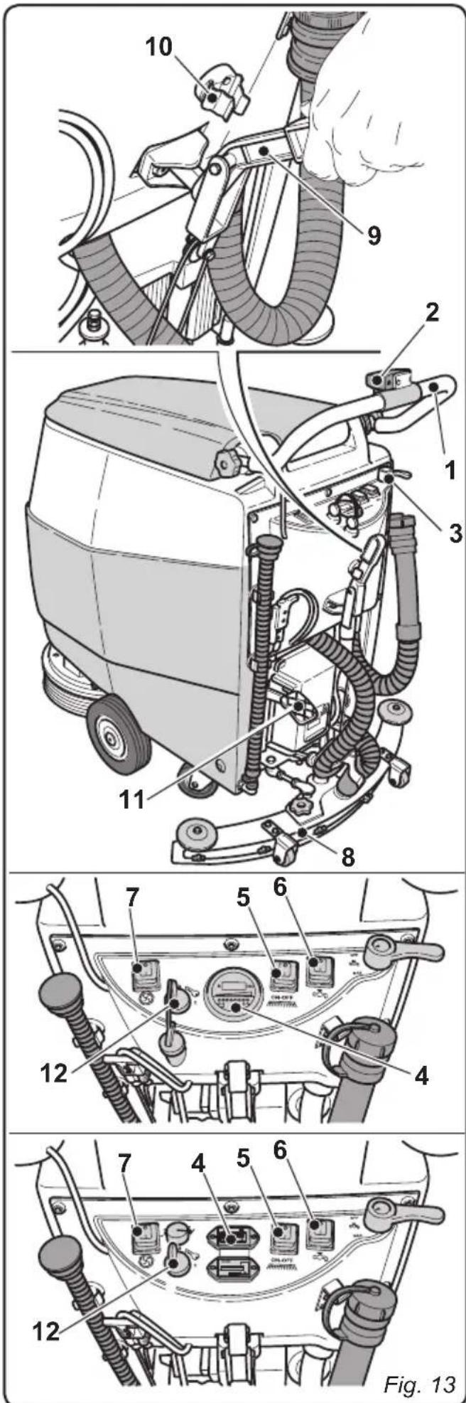
8.1.c - Using the machine
- After having activated the machine and chosen the desired cycle typology, start the cleaning operations: use the handlebar unit (1) to push the machine or use the proper commands (2) (buttons or levers) to activate the drive mechanism (for models which are equipped).

To avoid damaging the floor, do not use the machine in a fixed position with brush rotation activated

The correct way of cleaning and drying the floor is to move the machine forwards. Moving the machine backwards damages the blades as well as not allowing correct aspiration of the water present on the floor.
- If necessary, adjust the quantity of washing water using the tap (3).
- Check the status of the battery charge by the indicator (4).
8.1.d - End of use and switching off
- Once the cleaning operations have been completed, do not shut off the machine immediately: use switches (5) and (6) to deactivate water dispensing and brush rotation and continue with the suction unit in function in order to eliminate any residual liquid on the floor. When finished, press the switch (7) to shut off the suction unit.
- Lift up the floor squeezegee (8) by lifting up the lever (9), hooking it in the specific fixing clip (10).
- Lift up the brush by pressing the pedal (11) as far as it will go, fitting it in the designated slot.

WARNING:
Always lift up the squeegee at the end of cleaning in order to prevent the deformation of the rubber blades.
- Turn the key (12) to its "0" position to shut off the machine.
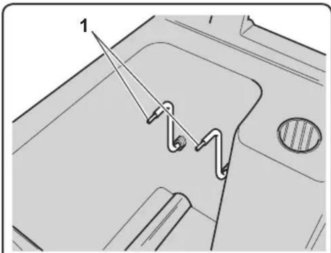
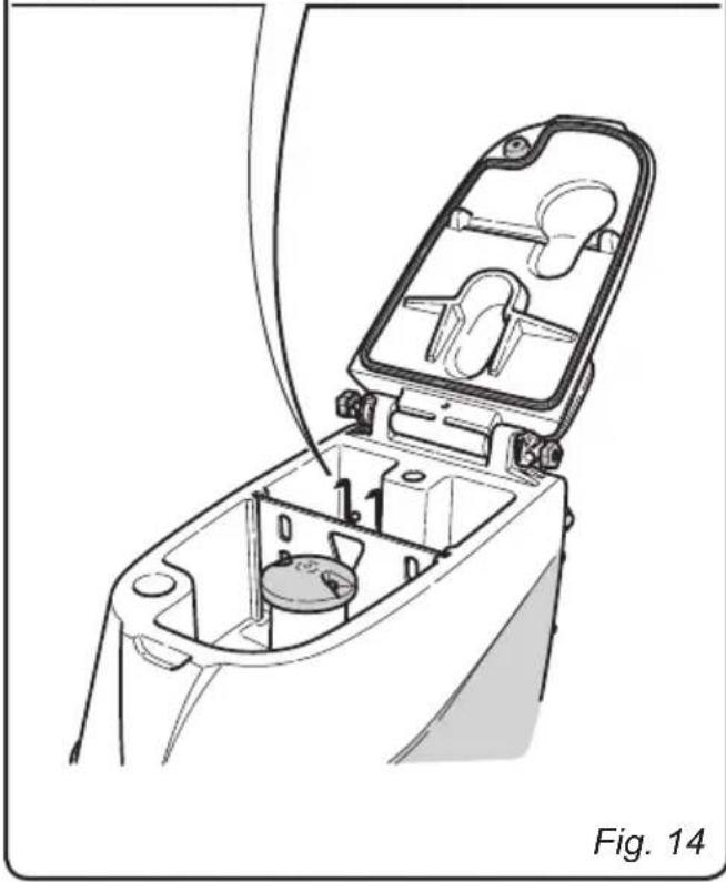
8.1.e - Maximum recovery tank water level alarm (Fig. 14)
If the suction unit shuts off while the machine is in function, this indicates that the level of the liquid in the recovery tank has reached the maximum level sensors (1), which are located within the tank itself.
Go to the water drainage station and drain the recovery tank as shown in the relative paragraph.
8.1.f - Probe height (Fig. 14)
The probes (1) are regulated for machine use on a 2% slope.
If, in the working environment, there are upward or downward sloping ramps of more than 2% , it is necessary to adjust the height of the probes in order to prevent damage to the aspiration turbine.

WARNING:
For adjustment, contact the Authorised Support Service.
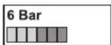
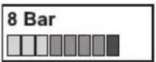
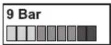
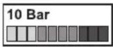
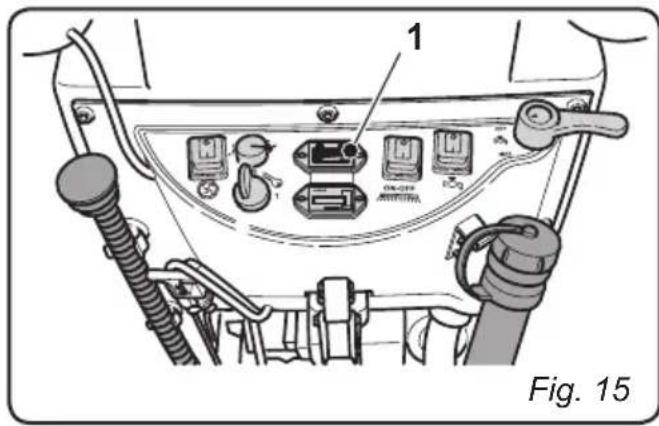
8.1.g - Alarms list (only for models with integrated drive mechanisms) (Fig. 15)
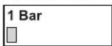
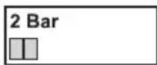
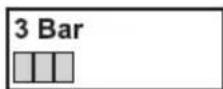
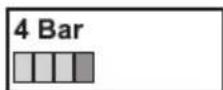
When a machine malfunction occurs, various bars, which correspond to specific alarms, will flash on the display (1). The alarms which correspond to each bar are described below.
In order to restore the machine's proper functionality, consult the list below and perform the recommended procedures.
If the recommended actions should not resolve the problem, contact Technical Assistance.
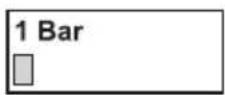
Fixed bars (not flashing), on the other hand, indicate the battery charge status:
- 1 Bar: minimum charge;
- 10 Bars: maximum charge;
Alarms list:
The batteries need to be recharged.
Check the connection between the motor and the electronic card.
The drive motor has short circuited.
Contact technical assistance
The battery charge has dropped below the configured threshold. The electronic card has inhibited certain functions.
Recharge the batteries

No function assigned.
The electronic card has deactivated the drive motor. The battery charger is probably connected.

Accelerator alarm (red levers on the handlebar unit).
Make sure that the accelerator is in its central position upon machine start up.
Alarm relative to the electronic card.
Check the connections.
Magnetic brake malfunction.
Check the connections for the brake and the drive motor.
Excessive voltage supplied to the electronic card.
Check the connections.
In addition to the possibilities indicated up until this point, it is also possible for all 10 bars to continuously scroll upon the display (1): this indicates that the machine has been activated with the accelerator engaged. Release the accelerator.
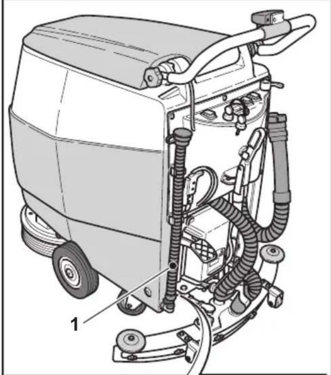
9.1 DRAINING THE RECOVERY WATER
(Fig. 16)
At the end of the washing cycle or when the recovery water tank (1) is full, it is necessary to empty the tank by proceeding as follows:

N.B.:
To dispose of the recovery water, comply with the standards in force in the country in which the machine is used.
- Position the machine near to a drain outlet.
- Disconnect the hose (2) from the support.
- Remove the cap (3) from the hose (2) and drain all the water contained in the tank.

N.B.:
The amount of water that comes out can be modulated by pressing on the end of the tube (2).
- Put the cap (3) back on the hose (2) and reposition it on the relative support.
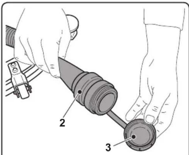
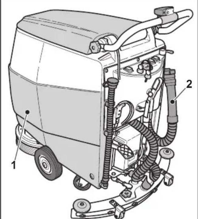
Fig. 16
10.1 MAINTENANCE AND CLEANING

WARNING:
For information and warnings regarding maintenance or cleaning, follow the information given in the "General warnings during maintenance" in chapter 1 in this manual.
OPERATIONS TO PERFORM DAILY
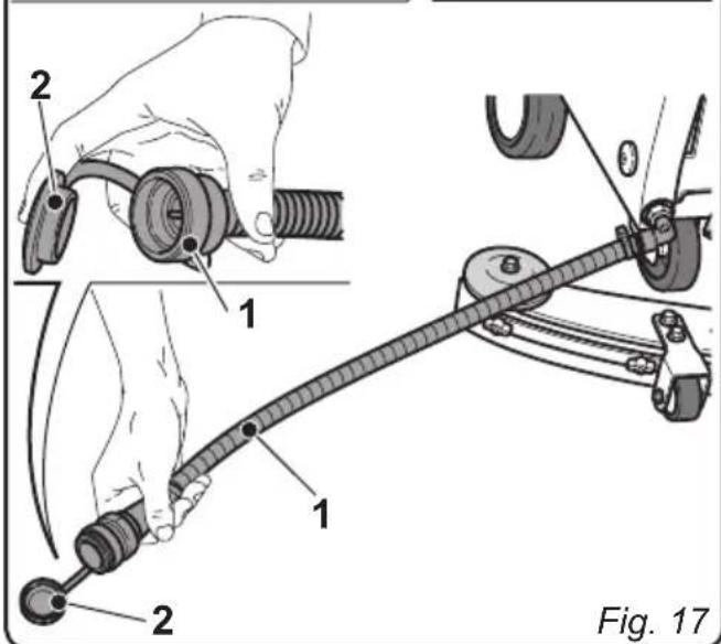
10.1.a - Emptying and cleaning the clean water tank (Fig. 17)

WARNING:
At the end of the washing operations, it is compulsory to drain and clean the clean water tank to prevent deposits or scaling.
After draining the recovery water tank, drain the clean water tank as follows:
- Position the machine over a drain outlet.
- Detach the tube (1) from its lodgings and lower it to the ground over the drain cover. If the cap (2) is closed, remove it and let the water drain out completely.
- Take the cover (3) off.
- Wash the inside of the tank, leaving the drain hose open and adding clean water through the top opening.
- Once finished cleaning, lift the tube (1), close it with its appropriate cap (2) and position it within its appropriate lodgings.
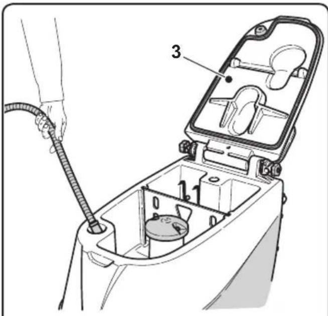
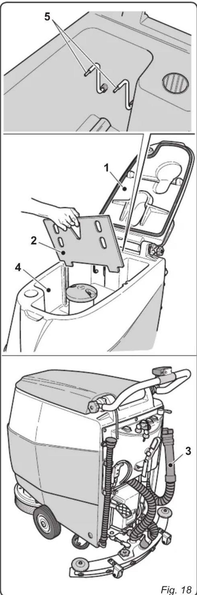
10.1.b - Cleaning the recovery water tank (Fig. 18)

WARNING:
At the end of the washing operations, it is compulsory to clean the recovery water tank to prevent deposits or scaling and the proliferation of bacteria, odours or mould.
- Drain the recovery water as shown in the relative paragraph, positioning the machine over a drain outlet.
- Take the cover (1) off.
- Remove the partition (2) and wash it using running water.
- Leaving the hose (3) lowered and the cap off, pour water into the tank (4) through a hose, cleaning it until clean water comes out of the drain hose.
- Clean the level probes (5) using a damp cloth, taking care not to deform them.
- Replace all the components in reverse order.
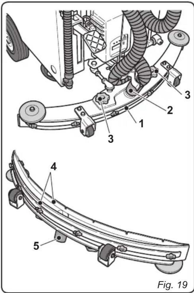
10.1.c - Cleaning the squeezegee (Fig. 19)
In order to clean the squeegee correctly (1), it is necessary to remove it as follows:
- Disconnect the hose (2) from the squeegee (1).
- Loosen the knobs (3) and remove the squeezegee (1).
- Wash the squeezegee and in particular the rubber blades (4) and the inside of the aspiration connector (5).

N.B.:
If, during washing, it is clear that the rubber blades (4) are damaged or worn, it is necessary to replace them or turn them over.
- Replace all the components in reverse order.
OPERATIONS TO PERFORM MONTHLY
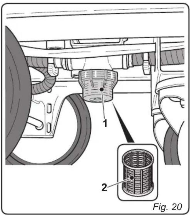
10.1.d - Cleaning the clean water filter (Fig. 20)
- Unscrew the transparent filter cover (1) and remove the filter (2).
- Clean the filter (2) using running water.
- Replace all the components in reverse order.
OPERATIONS TO PERFORM WHEN NECESSARY
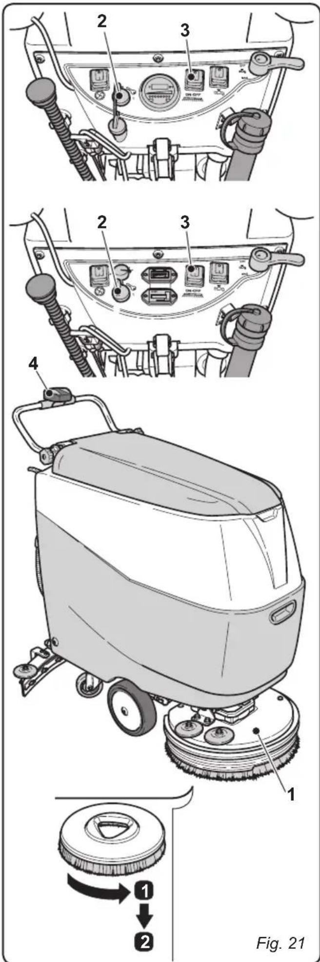
10.1.e - Replacing the brush (Fig. 21)
It becomes necessary to replace the brush when it is worn with bristles shorter than 2 cm or it must be replaced according to the type of floor to wash; to replace it, proceed as follows:
- Lift up the brush using the pedal as shown in the relative paragraph.
- Insert one hand under the brush-holder unit (1); to release the brush, rotate it sharply in the opposite direction to rotation.
- Replace the brush, positioning it under the brush-holder flange (1).
- Lower the brush-holder flange (1) using the pedal, as shown in the relative paragraph.
- Turn the key (2) to its "1" position.
- Press the switch (3) to enable the rotation of the brushes.
- Use the appropriate controls (4) on the handlebar unit to activate the rotation of the brushes until an audible "click" is heard. This indicates that the brush has been properly connected to the flange (1). Release the handlebar controls (4) to stop the rotation of the brushes.
- Turn the key (2) to its "0" position to shut off the machine.
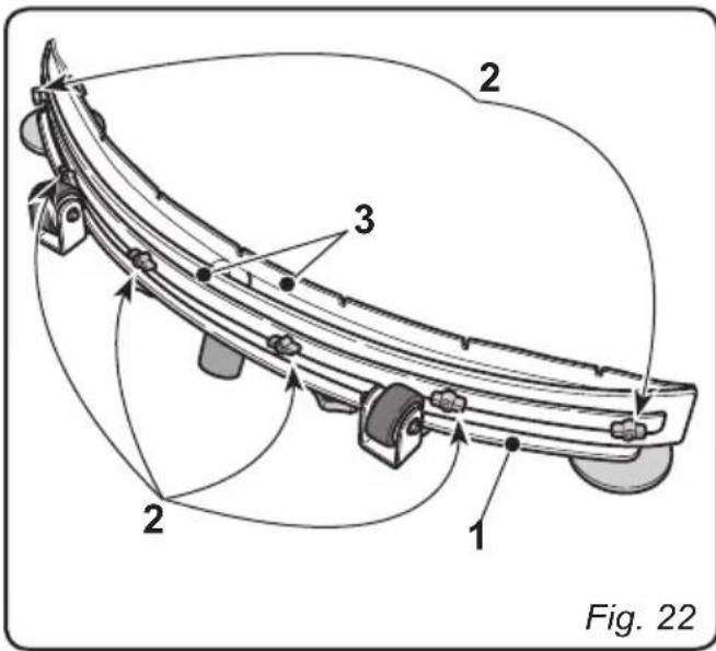
10.1.f - Replacing the squeezegee rubber blades (Fig. 22)
When it becomes clear that drying the floor is difficult or traces of water remain on the floor, it is necessary to check the wear on the squeezegee rubber blades (1):
- Remove the squeegee unit (1) as indicated in the "Cleaning the squeegee" paragraph.
- Loosen the finned nuts (2) and remove the rubber blades (3).

N.B.:
When the rubber blades (3) are worn on one side, on one occasion they may be turned over.
- Replace or turn over the rubber blades (3) without inverting them.
- Replace all the components in reverse order

N.B. :
It is possible to have two types of rubber blade.
Para rubber blades for all types of floor and polyurethane rubber blades for mechanical workshop floors which are dirty with oil.
10.1.g - Replacing the fuses (Fig. 23)

WARNING:
Replace the blown fuse with one with the same amperage.
- Remove the plug (1) from the socket (2).
- Remove the cover (3) to access the fuses.
Fuse (4) - 7,5A
Control panel protection.
Fuse (5) - Green 30A
Brush rotation motor protection.
Fuse (6) - Red 40A
Aspirator motor protection
- Put the cover (3) back on.
- In order to replace the fuse (7) on the positive pole of the battery, do the following:

WARNING:
Check that the recovery tank and the clean water tank are empty.
- Disconnect the plug (8).
- Remove the split pin (9) and lift up the tanks (10), using the handle (11) until they are completely overturned.
Fuse (7) - 75A
Battery fuse.
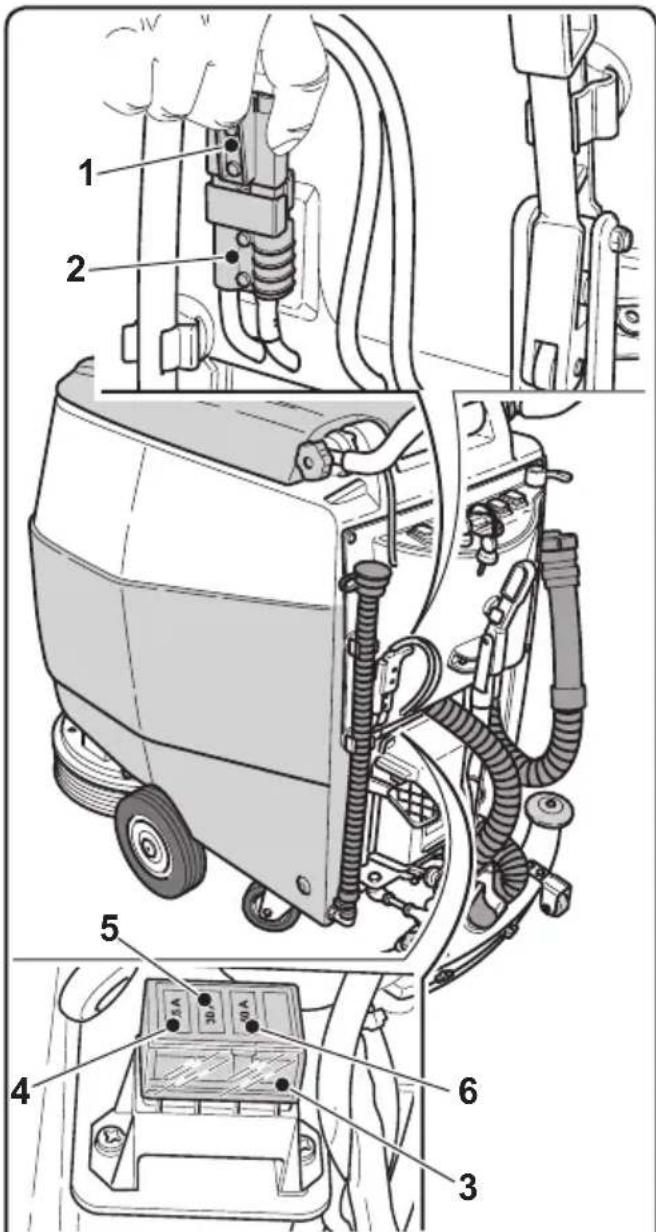
Fig. 23
10.1.h - Battery charger and digital instrument configuration (Fig. 24-25)

WARNING:
The machine leaves production with a standard configuration for operation with "Sonnenschein" gel batteries.
- Remove the cover (1) by unscrewing the screws (2).
Digital instrument configuration (only for models without an integrated drive mechanism)
- Locate the selector (4) on the back of the digital instrument (3):
- for acid batteries, turn the selector (4) to its "0" position.
- for gel batteries, turn the selector (4) to its "2" position.
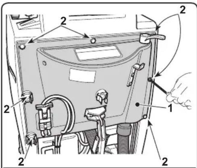
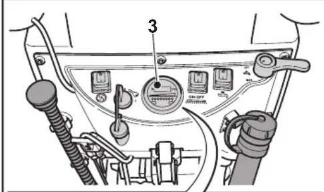
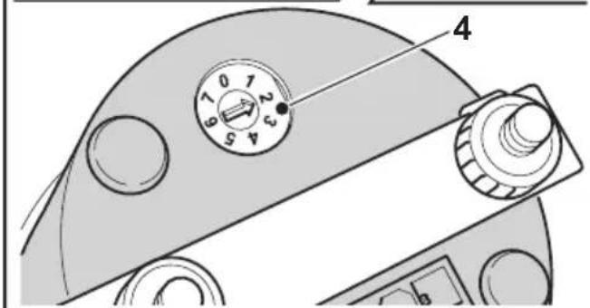
Fig. 24
Standard battery charger configuration for Sonnenschein gel batteries
- Lift the cover (X) and check that the switches (1 - 2 - 3 - 4) are set to the configuration shown in the diagram (C).
Perform the following operations to modify the configuration:
Battery charger configuration for gel batteries other than Sonnenschein
- Lift the cover (X) and check that the switches (1 - 2 - 3 - 4) are set to the configuration shown in the diagram (D).
Battery charger configuration for acid batteries
- Lift the cover (X) and check that the switches (1 - 2 - 3 - 4) are set to the configuration shown in the diagram (E).

WARNING:
Only modify switches (1 - 2 - 3 - 4); do not alter the positions of switches (5 - 6 - 7 - 8).
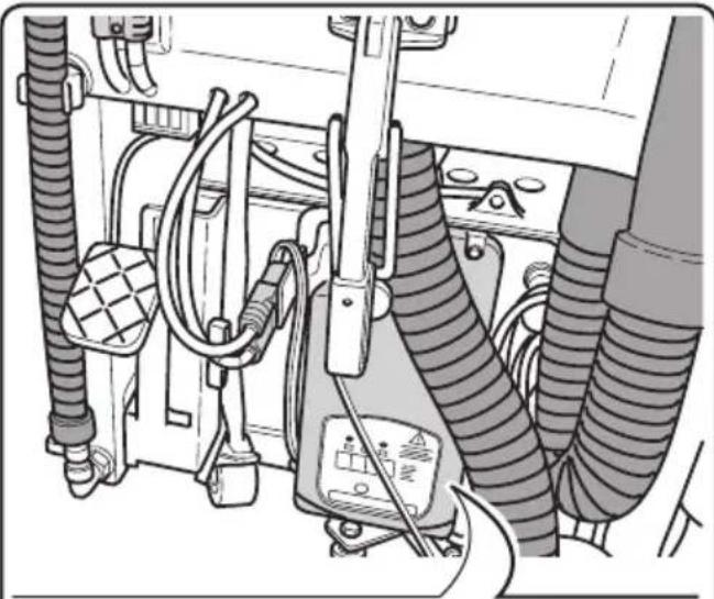
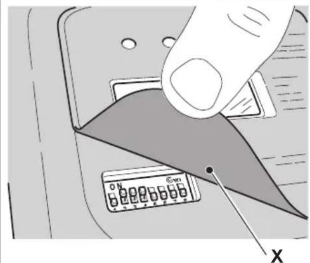
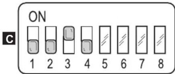
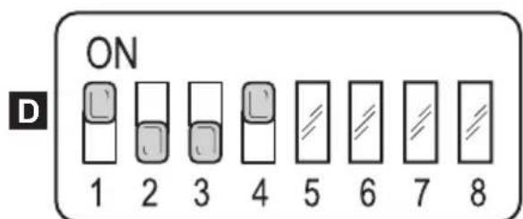
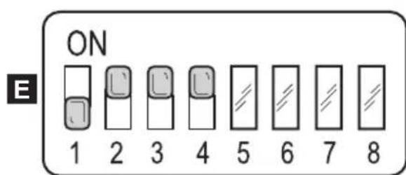
Fig. 25
TROUBLESHOOTING
| PROBLEM CAUSE | SE SOLUTION | |
| The machine does not turn on when the key is turned. | Low battery. Main fuse blown. | Check that the battery is charged. Replace the master 7,5A fuse. |
| The brush does not rotate. | Brush fuse blown. Brush rotation enabling switch not pressed | Replace the GREEN 30A brush motor fuse. Press the switch. |
| Aspirator does not work. Aspirator fuse blown. Suction unit switch not pressed. Recovery tank full. | Replace the RED 40A fuse for the suction unit's motor. Press the switch. Empty, wash and clean the tank and the probes. | |
| The machine does not dry well, leaving traces of water on the floor. | Aspirator off. Aspiration tube blocked. Recovery tank full. Squeezegee rubber blades worn. | Start up the aspirator. Check and if necessary clean the aspiration tube that connects the squeezegee to the recovery tank. Empty the recovery tank. Replace or turn over the squeezegee rubber blades. |
| No water comes out. | Tank empty. Solenoid valve enabling switch not pressed. Tap turned off. Filter blocked. Solenoid valve does not work. | Fill the tank. Press the switch. Open the tap Clean the filter. Call the technical support service. |
| PROBLEM CAUSE SOLUTION | ||
| Insufficient floor cleaning. Unsuitable brushes or detergent. Brush worn. | Use brushes or detergents which are suitable for the type of floor or dirt to be cleaned. Replace the brush. | |
WIRING DIAGRAMS
Models 45M45 - 45M55
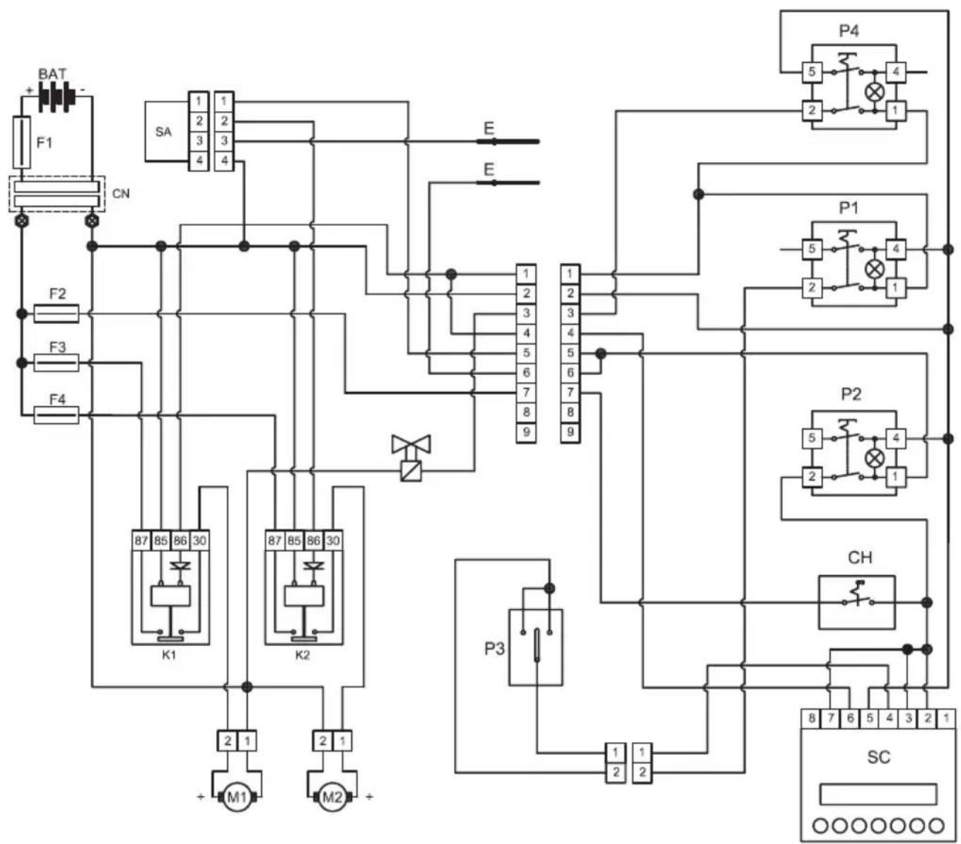
BAT 24V Battery
CH Key
CN Connector
E . Electrode
F1 75A Battery fuse
F2 .7.5A Key fuse
F3 30A Brush fuse
F4 40A Suction unit fuse
K1 Brush relay
K2 .Suction unit relay
M1.Brush motor
M2. Suction unit motor
P1………………………………………Brush button
P2 . Suction unit button
P3 Brush start button
P4 . Solenoid valve button
SA. Antifoam card
SC.Drain indicator ^+ counter
Model 45D55
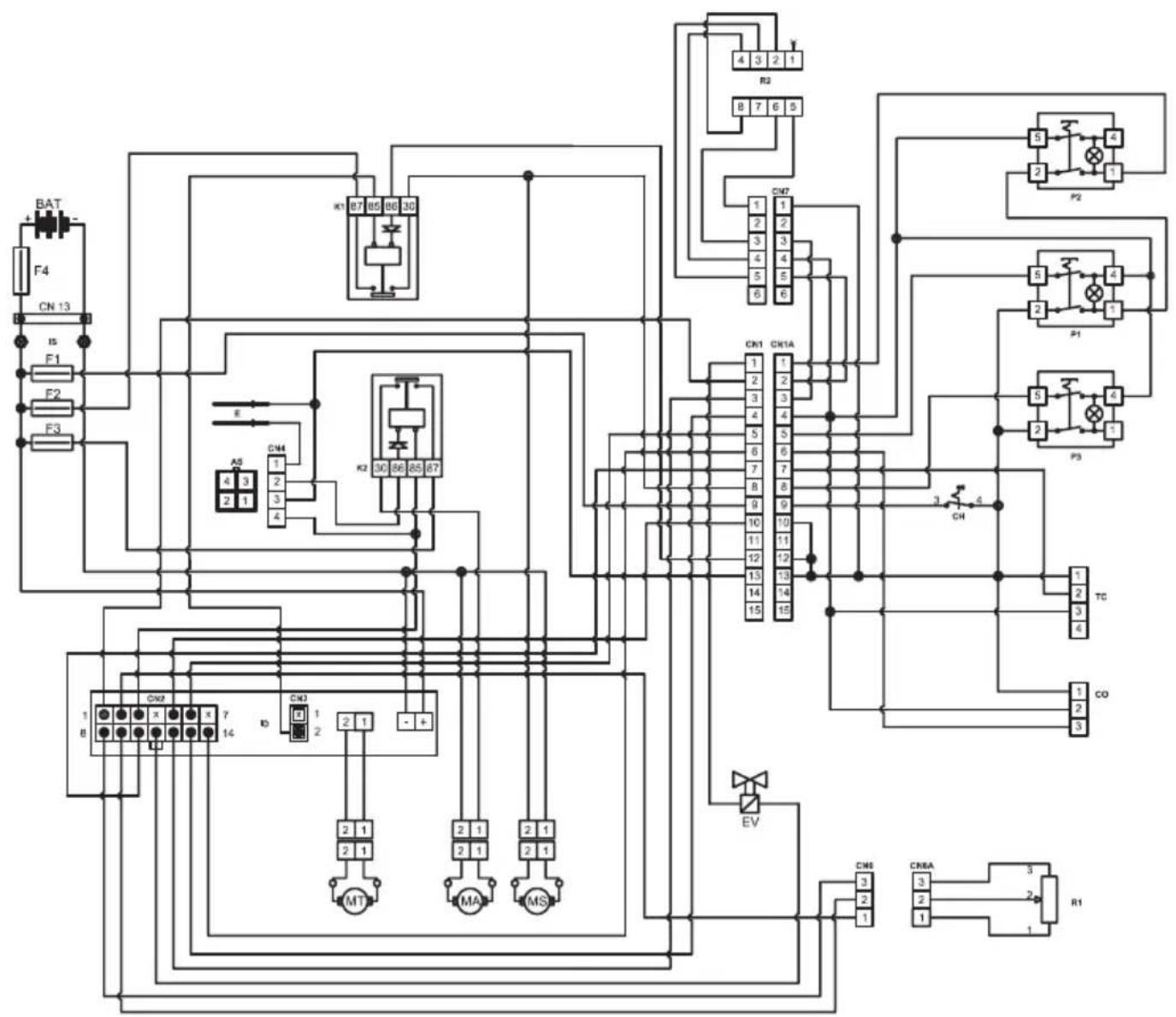
AS. Antifoam
BAT 24V Battery
CO Counter
CN1 15PIN Connector
CN2 ID control unit connector
CN3 ID control unit connector
CN4 Antifoam card connector
CN6 .To the PL potentiometer
CN7 To the handlebar unit
E . Electrodes
EV. Solenoid valve
F1 7.5A fuse
F2 30A fuse
F3 40A fuse
F4 75A fuse
K1 Brush relay
K2 Suction relay
ID I-Drive control unit
IS .insulators
MA Suction motor
MS Brush motor
MT Drive motor
P1 . Brush button
P2 . Solenoid valve button
P3 Suction button
R1 4.7K Potentiometer
R2 Handlebar unit accelerator
TC True charge
Model 45D60
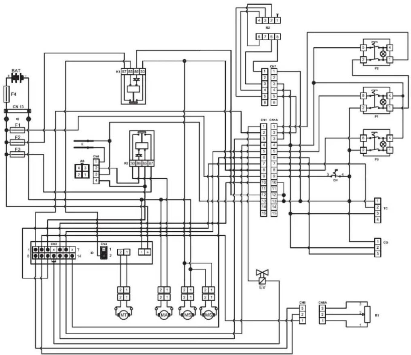
AS. Antifoam
BAT 24V Battery
CO Counter
CN1 15 PIN Connector
CN2 ID control unit connector
CN3 ID control unit connector
CN4 Antifoam card connector
CN6 .To the PL potentiometer
CN7 To the handlebar unit
E . Electrodes
EV. Solenoid valve
F1 7.5A fuse
F2 30A fuse
F3 40A fuse
F4 75A fuse
K1 Brush relay
K2 .Suction relay
ID I-Drive control unit
IS .insulators
MA Suction motor
MS Brush motor
MT Drive motor
P1 . Brush button
P2 . Solenoid valve button
P3 Suction button
R1 4.7K Potentiometer
R2 Handlebar unit accelerator
TC True charge
Cher client,
1.1 INTRODUCTION FR-5
8.1 FONCTIONNEMENT FR-17
-
1 Encoche: charge minimum;
-
10 Encoches: charge maximum.
Listedesalarmes:
A这其中 is a非常好, and it's also very useful. It's easy to use, and it's easy to understand.

NOTA:
PROBLEMAS - CAUSAS - SOLUÇões