
EY7460 - Screwdriver PANASONIC - Free user manual and instructions
Find the device manual for free EY7460 PANASONIC in PDF.
| Brand | Panasonic |
| Model | EY7460 |
| Product Type | Cordless Screwdriver |
| Power Source | Li-ion battery 21.6 V DC (3.6 V × 6 cells) |
| Battery Capacity | 3 Ah (model EY9L60) |
| Charger | Model EY0L80, full charge time: 60 min |
| No-load Speed (Low) | 100 - 400 min⁻¹ |
| No-load Speed (High) | 350 - 1500 min⁻¹ |
| Number of Clutch Settings | 18 positions + drill position |
| Clutch Torque | Approx. 1.0 - 6.9 N·m |
| Chuck Capacity | 1.5 mm - 13 mm (keyless chuck) |
| Max. Drilling in Wood | 38 mm |
| Max. Drilling in Metal | 13 mm |
| Max. Screwing (Wood Screws) | 10 mm |
| Total Length | 232 mm |
| Weight (with battery EY9L60) | 2.45 kg |
| Main Functions | Drilling, screwdriving, manual screwdriver function (up to 40 N·m), bit lock, LED light |
| Safety | Motor brake, overheat protection (motor and battery), overdischarge protection, switch lock |
| Maintenance | Clean with a dry, clean cloth; do not use water or solvent |
| Included Accessories | Auxiliary handle, charger EY0L80, battery EY9L60 (depending on kit) |
| Warranty | See included warranty card |
Frequently Asked Questions - EY7460 PANASONIC
User questions about EY7460 PANASONIC
0 question about this device. Answer the ones you know or ask your own.
Ask a new question about this device
Download the instructions for your Screwdriver in PDF format for free! Find your manual EY7460 - PANASONIC and take your electronic device back in hand. On this page are published all the documents necessary for the use of your device. EY7460 by PANASONIC.
USER MANUAL EY7460 PANASONIC
Operating Instructions
Bedienungsanleitung
natural_image
Line drawing of a handheld electric drill press (no text or symbols)Before operating this unit, please read these instructions completely and save this manual for future use.
| (A) | Keyless drill chuckSchlüsselfreies BohrfutterMandrin porte-foret sans filMandrino autoserranteBoorkop zonder sleutelMandril sin llaveNøglefri borepatronNyckellös borrchuckNøkkelfri drillchuckAvaimeton poran kiinnityslaiteБесключевой зажимной патронБезключовый затискний патрон | (B) | Clutch handleKupplungsringPoignée de l'embrayageImpugnatura frizioneKoppelingshandgreepMango de embragueKoblinghåndtagKopplingshandtagKoblingshåndtakKytkimen kahvaРукоятка муфтыРукоятка муфти |
| (C) | Speed selector switchBereichsschalterInterrupteur de sélection de vitesseRegolatore di velocitàSnelheidskeuzeschakelaarInterruptor selector de velocidadHastighedsvælgerHastighetsomkopplareHastighetskontrollNopeuden valintakytkinПереключатель выбора скоростиПеремикач вибору швидкості | (D) | Forward/Reverse leverRechts/Linkslauf SchalterLevier d'inversion marche avant-marche arrièreLeva di avanzamento/inversioneVoorwaarts/achterwaarts-hendelPalanca de avance/inversiónGreb til forlæns/baglæns retningRiktningsomkopplareForover/Revers bryterEteenpäin/taaksepäin vipuРычаг переключения вперед/назадВажіль перемикання вперед/назад |
| (E) | Alignment marksAusrichtmarkierungenMarques d'alignementMarcature allineamentoUitlijntekensMarcas de alineaciónFlugtemærkerAnpassningsmärkenOpprettingsmerkeSovitusmerkitМетки совмещенияМітки вирівнювання | (F) | Battery pack release buttonAkku-EntriegelungsknopfBouton de libération de batterie autonomeTasto di rilascio pacco batteriaAccu-ontgrendeltoetsBotón de liberación de bateríaUdløserknap til batteripakningFrigöringsknapp för batteriUtløserknapp for batteripakkeAkkupaketin irrotuspainikeКнопка освобождения батарейного блокаКнопка вивільнення батарейного блоку |
| (G) | Battery pack (EY9L60)Akku (EY9L60)Batterie autonome (EY9L60)Pacco batteria (EY9L60)Accu (EY9L60)Batería (EY9L60)Batteripakning (EY9L60)Batteri (EY9L60)Batteripakke (EY9L60)Akku (EY9L60)Батарейный блок (EY9L60)Батарейний блок (EY9L60) | (H) | Control panelBedienfeldPanneau de commandePannello di controlloBedieningspaneelPanel de controleKontrolpanelKontrollpanelKontrollpanelSäätöpaneeliПанель управленияПанель управління |
| (I) | Overheat warning lamp (battery/motor)Überhitzungs-Warnlampe (Akku/motor)Témoin d'avertissement de surchauffe (batterie/moteur)Spia avvertenza surriscaldamento (batteria/motore)Oververhitting-waarschuwingslampje (accu/motor)Luz de advertencia de sobrecalentamiento (batería/motor)Advarselslamp til overophedning (batteri/motoren)Varningslampa för överhettning (batteri/motorn)Varsellampe for overoppheting (batteri/motor)Ylikuumenemisen varoituslamppu (akku/moottoria)Предупреждающая лампочка перегрева (батареи/мотор)Попереджувальна лампочка перегріву (батареї/мотор) | (J) | LED light on/off buttonLED-Leuchten-EIN/AUS-TasteBouton Marche/Arrêt de la lumière DELTasto di accensione e spegnimento della luce LEDAan/uit-toets (ON/OFF) voor LED-lampjeBotón ON/OFF de luz LEDTÆND/SLUK-knap til LED-lysStrömbrytare för LED-ljusPÅ/AV-knapp for LED-lysLED-valon kytkin/katkaisupainikeКнопка включения/выключения светодиодной подсветкиКнопка ввімкнення/вимкнення світлодіодного підсвічування |
| (K) | LED lightLED-LeuchteLumière DELLuce LEDLED-lampjeLuz indicadoraLED-lysLED-ljusLED-lysLED-valoСветодиодная подсветкаСвітлодіодне підсвічування | (L) | Battery low warning lampAkkuladungs-WarnlampeTémoin d'avertissement de batterie basseSpia avvertenza batteria scaricaWaarschuwingslampje voor lage accuspanningLuz de aviso de baja carga de bateríaAdvarselslampes batterieffekt lavVarningslampa för svagt batteriVarsellampe for at batteriet er for lavtAlhaisen akkujännitteen varoituslamppuПредупреждающая лампочка низкого заряда батареиПопереджувальна лампочка низького заряду батареї |
| (M) | Variable speed control triggerBetriebsschalterGâchette de commande de vitesseGrilletto di controllo velocità variableStartschakelaar variabele snelheidDisparador del control de velocided variableKontroludløser for variabel hastighedSteglös varvtalsreglerareHovedbryter, trinnløsNopeudensäätökytkinПереключатель регулировки переменной скоростиПеремикач регулювання змінної швидкості | (N) | Support handleZusatzgriffManche de supportManiglia di sostegnoSteungreepMango de soporteHjælpehåndtagStödhandtagStøttehåndtakTukikahvaПоддерживающая рукояткаПідтримуюча рукоятка |
| (O) | Battery charger (EY0L80)Ladegerät (EY0L80)Chargeur de batterie (EY0L80)Caricabatterie (EY0L80)Acculader (EY0L80)Cargador de batería (EY0L80)Batterioplader (EY0L80)Batteriladdare (EY0L80)Batterilader (EY0L80)Akkulaturi (EY0L80)Зарядное устройство (EY0L80)Зарядний пристрій (EY0L80) | (P) | Battery pack coverAkuabdeckungCouvercle de la batterie autonomeCoperchio pacco batteriaAccudekselCubierta de bateríaAkuafdækningBatterilockBatteripakkedekselAkun kansiКрышка аккумуляторной батареиКришка аккумуляторної батареї |
| (Q) | Ni-MH/Ni-Cd battery pack dockNi-MH/Ni-Cd-AkkuladeschachtPoste d'accueil de la batterie autonome Ni-MH/Ni-CdSpazio raccordo pacco batteria Ni-MH/Ni-CdNi-MH/Ni-Cd accuhouderEnchufe de carga de batería Ni-MH/Ni-CdNi-MH/Ni-Cd batteripakningsdokDocka för NiMH/NiCd-batteriDokk for Ni-MH/Ni-Cd-batteripakkeNi-MH/Ni-Cd akun liitinУглубление для установки никель-металлогидридного батарейного блока/никель-кадмиевого батарейного блокаЗаглиблення для встановлення нікель-метал-гідридного батарейного блоку/нікель-кадмієвого батарейного блоку | (R) | Li-ion battery pack dockLi-ion-AkkuladeschachtPoste d'accueil de la batterie autonome Li-ionSpazio raccordo pacco batteria Li-ionLi-ion accuhouderEnchufe de carga de batería Li-iónLi-ion batteripakningsdokDocka för litiumjonbatteriDokk for Li-ion-batteripakkeLi-ioniakun liitinУглубление для установки литий-ионного батарейного блокаЗаглиблення для встановлення літій-іонного батарейного блоку |
I. INTENDED USE
These tools can be used to tighten screws in clutch mode and to drill holes in wood and metal in drill mode. Additionally, model EY7960 can be used to drill holes in soft concrete and similar materials in hammer mode.
Read the Safety Instructions booklet and the following before using.
II. ADDITIONAL SAFETY RULES
1) Wear ear protectors.
Exposure to noise can cause hearing loss.
2) Use auxiliary handle supplied with the tool.
Loss of control can cause personal injury.
3) Hold power tools by insulated gripping surfaces when performing an operation where the cutting tool may contact hidden wiring; contact with a "live" wire will make exposed metal parts of the tool "live" and shock the operator.
4) Wear a dust mask, if the work causes dust.
5) Be aware that this tool is always in an operating condition, since it does not have to be plugged into an electrical outlet.
6) When drilling or driving into walls, floors, etc., "live" electrical wires may be encountered. DO NOT TOUCH THE CHUCK OR ANY FRONT METAL PARTS OF THE TOOL! Hold the tool only by the plastic handle to prevent electric shock in case you drill or drive into a "live" wire.
7) If the bit becomes jammed, immediately turn the trigger switch off to prevent an overload, which can damage the battery pack or motor.
Use reverse motion to loosen jammed bits.
8) Do NOT operate the
Forward/Reverse lever when the trigger switch is on. The battery will discharge rapidly and damage to the unit may occur.
9) During charging, the charger may become slightly warm. This is normal. Do NOT charge the battery for a long period.
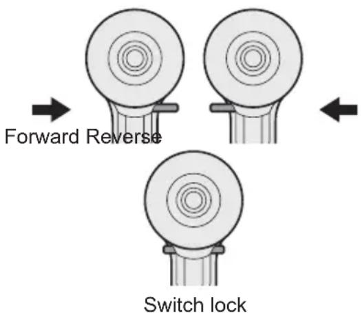
10) When storing or carrying the tool, set the Forward/Reverse lever to the center position (switch lock).
11) Do not strain the tool by holding the speed control trigger halfway (speed control mode) so that the motor stops.
12) Do not operate the speed selector switch (LOW-HIGH) while pulling on the speed control trigger. This can cause the rechargeable battery to wear quickly or damage the internal mechanism of the motor.
| Symbol | Meaning |
| V | Volts |
| --- | Direct current |
| n_0 | No load speed |
| ...min-1 | Revolutions orreciprocations per minutes |
| Ah | Electrical capacity ofbattery pack |
| ∪ | Forward rotation |
| ∪ | Reverse rotation |
| ↑ | Rotation with hammering |
 | Rotation only |
 | Read the operatinginstructions before use. |
 | For indoor use only. |

WARNING:
- Do not use other than the Panasonic battery packs that are designed for use with this rechargeable tool.
- Do not dispose of the battery pack in a fire, or expose it to excessive heat.
- Do not drive the likes of nails into the battery pack, subject it to shocks, dismantle it, or attempt to modify it.
- Do not allow metal objects to touch the battery pack terminals.
- Do not carry or store the battery pack in the same container as nails or similar metal objects.
- Do not charge the battery pack in a high-temperature location, such as next to a fire or in direct sunlight. Otherwise, the battery may overheat, catch fire, or explode.
- Never use other than the dedicated charger to charge the battery pack. Otherwise, the battery may leak, overheat, or explode.
• After removing the battery pack from the tool or the charger, always reattach the pack cover. Otherwise, the battery contacts could be shorted, leading to a risk of fire.
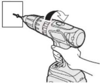
III.ASEMBLY Attaching or Removing Bit
NOTE:
When attaching or removing a bit, disconnect battery pack from tool or place the switch in the center position (switch lock).
This tool is equipped with a keyless drill chuck.
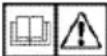
1. Attachment
Insert the bit and turn the lock collar clockwise (looking from the front) to tighten firmly until it stops clicking.
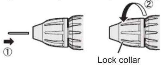
2. Removal
Turn the lock collar counterclockwise (looking from the front), then remove the bit.
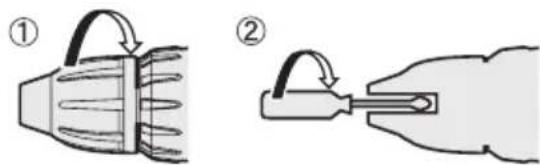
NOTE:
If excessive play occurs in the chuck, secure the drill in place and ① open the chuck jaws by turning the lock collar and ② tighten the screw (left-handed screw) with a screwdriver by turning it counterclockwise (viewed from the front).
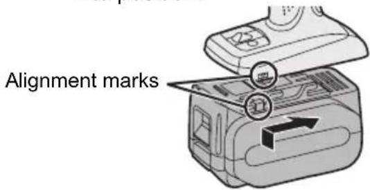
Attaching or Removing Battery Pack
1. To connect the battery pack:
Line up the alignment marks and attach the battery pack.
- Slide the battery pack until it locks into position.
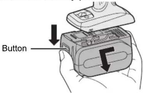
2. To remove the battery pack:
Push on the button from the front to release the battery pack.
Support handle
Place the support handle at your favorite position and tighten the handle securely.
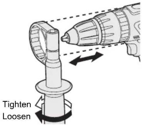
Remove the handle when placing the tool in the storage case.
IV. OPERATION
[Main Body]
Switch Operation
- The speed increases with the amount of depression of the trigger. When beginning work, depress the trigger slightly to start the rotation slowly.
- A feedback electronic controller is used to give a strong torque even in low speed.
- The brake operates when the trigger is released and the motor stops immediately.
NOTE:
When the brake operates, a braking sound may be heard. This is normal.
Switch and Forward/Reverse Lever Operation
CAUTION:
To prevent damage, do not operate Forward/Reverse lever until the bit comes to a complete stop.
Forward Rotation Switch Operation
- Push the lever for forward rotation.
- Depress the trigger switch slightly to start the tool slowly.
- The speed increases with the amount of depression of the trigger for efficient tightening of screws and drilling. The brake operates and the chuck stops immediately when the trigger is released.
- After use, set the lever to its center position (switch lock).
Reverse Rotation Switch Operation
- Push the lever for reverse rotation. Check the direction of rotation before use.
- Depress the trigger switch slightly to start the tool slowly.
- After use, set the lever to its center position (switch lock).
Clutch Torque Setting
Adjust the torque to one of the 18 clutch settings or "2" position (EY7460).
Adjust the torque to one of the 18 clutch settings or "½", "ₜ" position (EY7960).
NOTE:
Always make sure to stop operation of the tool and disengage it from the work, when you select Hammering mode from Drilling mode or when you shift to Drilling mode from Hammering mode by rotating clutch handle.
CAUTION:
Set the clutch setting at this mark (◀) before actual operation.
Speed Selection
Choose a low or high speed to suit the use.
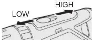
The more the variable speed control trigger is pulled, the higher the speed becomes.
CAUTION:
- Check the speed selector switch before use.
- Use at low speed when high torque is needed during operation. (Using at high speed when high torque is required may cause a motor breakdown.)
- Do not operate the speed selector switch (LOW-HIGH) while pulling on the speed control trigger. This can cause the rechargeable battery to wear quickly or damage the internal mechanism of the motor.
* See specifications for "MAXIMUM RECOMMENDED CAPACITIES".
CAUTION:
- To prevent excessive temperature increase of the tool surface, do not operate the tool continuously using two or more battery packs. The tool needs cool-off time before switching to another pack.
- Do not close up vent holes on the sides of the body during operation. Otherwise, the machine function is adversely affected to cause a failure.
- Do NOT strain the tool (motor). This may cause damage to the unit.
- Use the tool in such a way as to prevent the air from the body vent holes from blowing directly onto your skin. Otherwise, you may get burned.
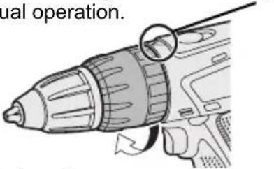
Bit-locking Function
- With the trigger switch not engaged and a screwdriver bit locked in place, the tool can be used as a manual screwdriver (up to 40 N·m, 408 kgf·cm, 353 in-lbs).
There will be a little play in the chuck, but this is not a malfunction.
- This feature is handy for tightening screws that require more torque than the maximum torque of the driver (position 2 on the clutch), for confirming the tightness of a screw or to loosen an extremely tight screw.
natural_image
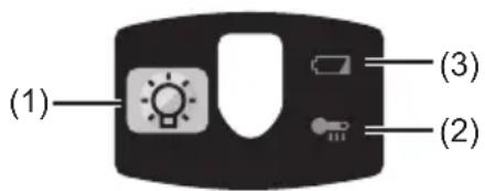
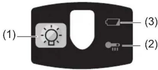
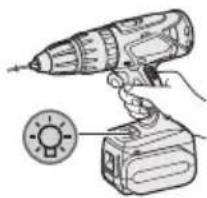
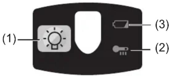
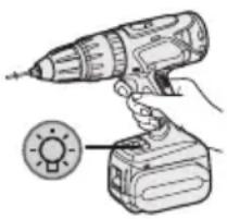
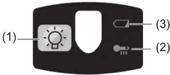
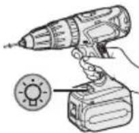
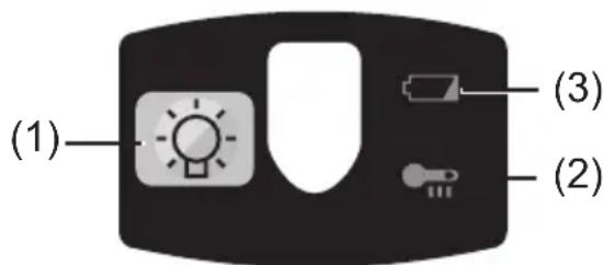
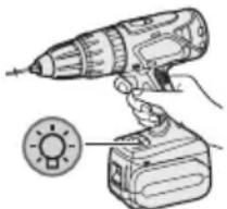
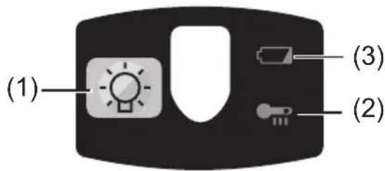
Illustration of a hand using a power drill on a handheld device (no text or symbols visible)Control Panel
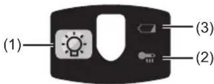
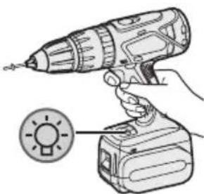
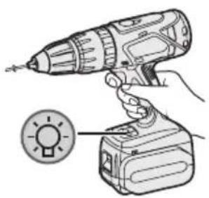
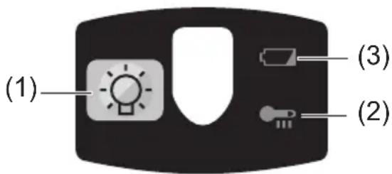
(1) LED light
natural_image
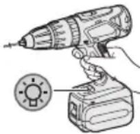
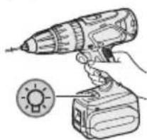
Illustration of a hand using a power tool to lift a light bulb (no text or symbols present)Before the use of LED light, always pull the power switch once.
Press the LED light button.
The light illuminates with very low current, and it does not adversely affect the performance of the tool during use or its battery capacity.
CAUTION:
- The built-in LED light is designed to illuminate the small work area temporarily.
- Do not use it as a substitute for a regular flashlight, since it does not have enough brightness.
• LED light turns off when the tool has not been used for 5 minutes.
Caution: DO NOT STARE INTO BEAM.
Use of controls or adjustments or performance of procedures other than those specified herein may result in hazardous radiation exposure.
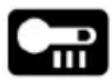
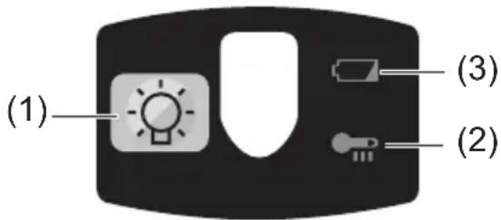
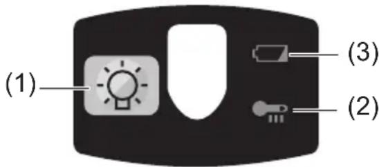
(2) Overheat warning lamp
Off
(normal
operation)

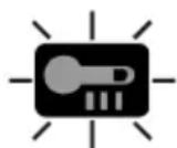
Illuminated: Overheat (motor)
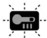
Flashing: Overheat (battery)
Indicates operation has been halted due to motor or battery overheating.
To protect the motor or battery, be sure to note the following when carrying out this operation.
- If the motor or battery becomes hot, the protection function will be activated and the motor or battery will stop operating. The overheat warning lamp on the control panel illuminates or flashes when this feature is active.
- If the overheating protection feature activates, allow the tool to cool thoroughly (at least 30 minutes). The tool is ready for use when the overheat warning lamp goes out.
- Avoid using the tool in a way that causes the overheating protection feature to activate repeatedly.
- If the tool is operated continuously under high-load conditions or if it is used in hot-temperature conditions (such as during summer), the overheating protection feature may activate frequently.
- If the tool is used in cold-temperature conditions (such as during winter) or if it is frequently stopped during use, the overheating protection feature may not activate.
(3) Battery low warning lamp

Off
(normal
operation)

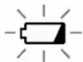
Flashing
(No charge)
Battery protection
feature active
Excessive (complete) discharging of lithium ion batteries shortens their service life dramatically. The driver includes a battery protection feature designed to prevent excessive discharging of the battery pack.
- The battery protection feature activates immediately before the battery loses its charge, causing the battery low warning lamp to flash.
- If you notice the battery low warning lamp flashing, charge the battery pack immediately.
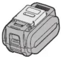
[Battery Pack]
For Appropriate Use of Battery pack
Li-ion Battery pack (EY9L60)
- For optimum battery life, store the Li-ion battery pack following use without charging it.
- When charging the battery pack, confirm that the terminals on the battery charger are free of foreign substances such as dust and water etc. Clean the terminals before charging the battery pack if any foreign substances are found on the terminals.
The life of the battery pack terminals may be affected by foreign substances such as dust and water etc. during operation.
- When battery pack is not in use, keep it away from other metal objects like: paper clips, coins, keys, nails, screws, or other small metal objects that can make a connection from one terminal to another.
Shorting the battery terminals together may cause sparks, burns or a fire.
- When operating the battery pack, make sure the work place is well ventilated.
- When the battery pack is removed from the main body of the tool, replace the battery pack cover immediately in order to prevent dust or dirt from contaminating the battery terminals and causing a short circuit.
natural_image
Illustration of a mechanical device with no visible text or symbolsBattery Pack Life
The rechargeable batteries have a limited life. If the operation time becomes extremely short after recharging, replace the battery pack with a new one.
Battery Recycling
ATTENTION:
For environmental protection and recycling of materials, be sure that it is disposed of at an officially assigned location, if there is one in your country.
[Battery Charger]
Charging
Cautions for the Li-ion Battery Pack
- If the temperature of the battery pack falls approximately below -10^ (14°F), charging will automatically stop to prevent degradation of the battery.
Common Cautions for the Li-ion/Ni-MH/Ni-Cd Battery Pack
- The ambient temperature range is between 0^ (32°F) and 40^ (104°F).
If the battery pack is used when the battery temperature is below 0^ C ( 32^ F), the tool may fail to function properly. - When charging a cool battery pack (below 0°C (32°F)) in a warm place, leave the battery pack at the place and wait for more than one hour to warm up the battery to the level of the ambient temperature.
- Cool down the charger when charging more than two battery packs consecutively.
- Do not insert your fingers into contact hole, when holding charger or any other occasions.
CAUTION:
To prevent the risk of fire or damage to the battery charger.
- Do not use power source from an engine generator.
- Do not cover vent holes on the charger and the battery pack.
- Unplug the charger when not in use.
Li-ion Battery Pack
NOTE:
Your battery pack is not fully charged at the time of purchase. Be sure to charge the battery before use.
Battery charger (EY0L80)
1. Plug the charger into the AC outlet.
NOTE:
Sparks may be produced when the plug is inserted into the AC power supply, but this is not a problem in terms of safety.
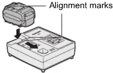
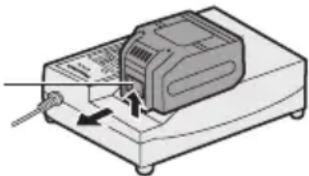
2. Insert the battery pack firmly into the charger.
- Line up the alignment marks and place the battery onto the dock on the charger.
- Slide forward in the direction of the arrow.
3. During charging, the charging lamp will be lit.
When charging is completed, an internal electronic switch will automatically be triggered to prevent overcharging.
- Charging will not start if the battery pack is warm (for example, immediately after heavy-duty operation). The orange standby lamp will be flashing until the battery cools down.
Charging will then begin automatically.
4. The charge lamp (green) will flash slowly once the battery is approximately 80% charged.
5. When charging is completed, the charging lamp will start flashing quickly in green color.
- If the temperature of the battery pack is 0^ C or less, charging takes longer to fully charge the battery pack than the standard charging time. Even when the battery is fully charged, it will have approximately 50% of the power of a fully charged battery at normal operating temperature.
- If the power lamp does not light immediately after the charger is plugged in, or if after the standard charging time the charging lamp does not flash quickly in green, consult an authorized service center.
- If a fully charged battery pack is inserted into the charger again, the charging lamp lights up. After several minutes, the charging lamp may flash quickly to indicate the charging is completed.
- Remove the battery pack while the battery pack release button is held up.
Battery pack release button
natural_image
Diagram of a device with a button and pointer, no visible text or symbolsNi-MH/Ni-Cd Battery Pack
NOTE:
When you charge the battery pack for the first time, or after prolonged storage, charge it for about 24 hours to bring the battery up to full capacity.
Battery charger (EY0L80)
1. Plug the charger into the AC outlet.
NOTE:
Sparks may be produced when the plug is inserted into the AC power supply, but this is not a problem in terms of safety.
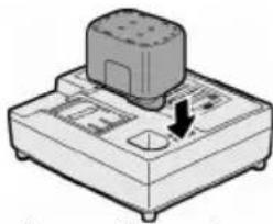
- Insert the battery pack firmly into the charger.
natural_image
Illustration of a mechanical device with a button and arrow, no visible text or symbols- During charging, the charging lamp will be lit.
When charging is completed, an internal electronic switch will automatically be triggered to prevent overcharging.
- Charging will not start if the battery pack is warm (for example, immediately after heavy-duty operation).
The orange standby lamp will be flashing until the battery cools down.
Charging will then begin automatically.
-
When charging is completed, the charging lamp will start flashing quickly in green color.
-
If the charging lamp does not light immediately after the charger is plugged in, or if after the standard charging time the charging lamp does not flash quickly in green, consult an authorized service center.
-
If a fully charged battery pack is inserted into the charger again, the charging lamp lights up. After several minutes, the charging lamp may flash quickly to indicate the charging is completed.
LAMP INDICATIONS


Green Lit
Charger is plugged into the AC outlet.
Ready to charge.
Green Flashing Quickly
Charging is completed. (Full charge.)
Green Flashing
Battery is approximately 80% charged. (Usable charge.
Li-ion only.)
Green Lit
Now charging.
Orange Lit
Battery pack is cool.
The battery pack is being charged slowly to reduce the load on the battery. (Li-ion only.)
Orange Flashing
Battery pack is warm. Charging will begin when temperature of battery pack drops.
If the temperature of the battery pack is -10^ or less, the charging status lamp (orange) will also start flashing.
Charging will begin when the temperature of the battery pack goes up (Li-ion only).
Charging Status Lamp
Left: green Right: orange will be displayed.
Both Orange and Green Flashing Quickly
Charging is not possible. Clogged with dust or malfunction of the battery pack.
Information for Users on Collection and Disposal of Old Equipment and used Batteries
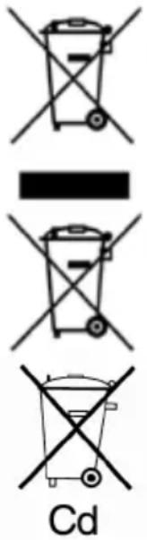
These symbols on the products, packaging, and/or accompanying documents mean that used electrical and electronic products and batteries should not be mixed with general household waste.
For proper treatment, recovery and recycling of old products and used batteries, please take them to applicable collection points, in accordance with your national legislation and the Directives 2002/96/EC and 2006/66/EC.
By disposing of these products and batteries correctly, you will help to save valuable resources and prevent any potential negative effects on human health and the environment which could otherwise arise from inappropriate waste handling.
For more information about collection and recycling of old products and batteries, please contact your local municipality, your waste disposal service or the point of sale where you purchased the items.
Penalties may be applicable for incorrect disposal of this waste, in accordance with national legislation.
For business users in the European Union
If you wish to discard electrical and electronic equipment, please contact your dealer or supplier for further information.
[Information on Disposal in other Countries outside the European Union]
These symbols are only valid in the European Union. If you wish to discard these items, please contact your local authorities or dealer and ask for the correct method of disposal.
Note for the battery symbol (bottom two symbol examples):
This symbol might be used in combination with a chemical symbol. In this case it complies with the requirement set by the Directive for the chemical involved.
V. MAINTENANCE
Use only a dry, soft cloth for wiping the unit. Do not use a damp cloth, thinner, benzine, or other volatile solvents for cleaning.
VI. ACCESSORIES
Use only bits suitable for size of drill's chuck.
VII.APPENDIX
MAXIMUM RECOMMENDED CAPACITIES
| Model | EY7460 | EY7960 | |
| Screw driving | Machine screw M8 | ||
| Wood screw ø 10 mm (3/8") | |||
| Self-drilling screw ø 6 mm (15/64") | |||
| Drilling | For Wood ø 38 mm (1-1/2") | ||
| For Metal ø 13 mm (1/2") | |||
| For Masonry --- 13 mm (1/2") | |||
VIII. SPECIFICATIONS MAIN UNIT
| Model | EY7460 | EY7960 | |
| Motor voltage 21.6 V DC | |||
| No load speed | Low 100 - 400 min | -1 (rpm) | |
| High 350 - 1500 min | -1 (rpm) | ||
| Blows Rate Per Minute | Low --- 1800 - 7200 min | -1 (bpm) | |
| High --- | 6300 - 27000 min | -1 (bpm) | |
| Chuck capacity ø 1.5 mm - ø 13 mm (1/16" - 1/2") | |||
| Clutch torque | Approx. 1.0 N·m (10 kgf-cm, 8.8 in-lbs) – 6.9 N·m (70 kgf-cm, 61 in-lbs) | ||
| Overall length | 232 mm (9-1/8") | 245 mm (9-5/8") | |
| Weight (with battery pack: EY9L60) | 2.45 kg (5.39 lbs) | 2.55 kg (5.61 lbs) | |
BATTERY PACK
| Model | EY9L60 |
| Storage battery | Li-ion Battery |
| Battery voltage | 21.6 V DC (3.6 V x 6 cells) |
| Capacity | 3 Ah |
BATTERY CHARGER
| Model | EY0L80 |
| Rating | See the rating plate on the bottom of the charger. |
| Weight | 0.95 kg (2.1 lbs) |
[Li-ion battery pack]
| Charging time | 3 Ah | 14.4 V 21.6 V | 28.8 V | |
| EY9L40 EY9L60 Usable: 35 min.Full: 50 min. | EY9L80 Usable: 45 min.Full: 60 min. | Usable: 55 min.Full: 70 min. |
[Ni-Cd/Ni-MH battery pack]
| Charging time | 7.2 V 9.6 V 12 V 15 | 6 V 18 V 24 V | |||||
| 1.2 Ah | EY9065 EY9066 | EY9080 EY9086 | EY9001 EY9006 | ||||
| 20 min. | |||||||
| 1.7 Ah | EY9180 EY9182 | EY9101 EY9103 | |||||
| 25 min. | |||||||
| 2 Ah | EY9168 EY9188 | EY9106 EY9107 EY9108 | EY9136 | EY9116 EY9117 | |||
| 30 min. 60 min. | |||||||
| 3 Ah | EY9200 EY9230 EY9210 45 min. | 10 | 90 min. | ||||
| 3.5 Ah | EY9201 EY9231 EY9251 55 min. 65 min. | 51 | |||||
NOTE: This chart may include models that are not available in your area. Please refer to the latest general catalogue.
NOTE: For the dealer name and address, please see the included warranty card.
ONLY FOR U. K.
IX. ELECTRICAL PLUG INFORMATIO
FOR YOUR SAFETY PLEASE READ THE FOLLOWING TEXT CAREFULLY
This appliance is supplied with a moulded three pin mains plug for your safety and convenience.
A 5 amp fuse is fitted in this plug.
Should the fuse need to be replaced please ensure that the replacement fuse has a rating of 5 amp and that it is approved by ASTA or BSI to BS1362.
Check for the ASTA mark 🎨 or the BSI mark 🏠 on the body of the fuse.
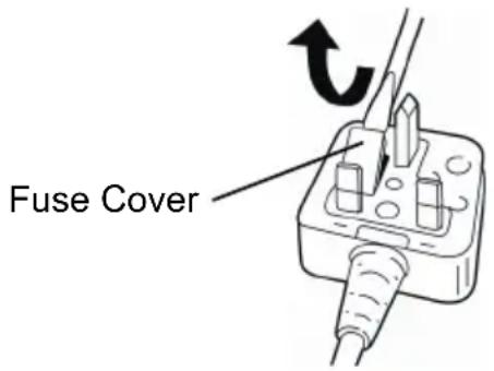
If the plug contains a removable fuse cover you must ensure that it is refitted when the fuse is replaced.
If you lose the fuse cover the plug must not be used until a replacement cover is obtained.
A replacement fuse cover can be purchased from your local Panasonic Dealer.
IF THE FITTED MOULDED PLUG IS UNSUITABLE FOR THE SOCKET OUTLET IN YOUR HOME THEN THE FUSE SHOULD BE REMOVED AND THE PLUG CUT OFF AND DISPOSED OF SAFELY.
THERE IS A DANGER OF SEVERE ELECTRICAL SHOCK IF THE CUT OFF PLUG IS INSERTED INTO ANY 13 AMP SOCKET.
If a new plug is to be fitted please observe the wiring code as shown below.
If in any doubt please consult a qualified electrician.
IMPORTANT:
The wires in this mains lead are coloured in accordance with the following code:
Blue: Neutral
Brown: Live
As the colours of the wire in the mains lead of this appliance may not correspond with the coloured markings identifying the terminals in your plug, proceed as follows.
The wire which is coloured BLUE must be connected to the terminal in the plug which is marked with the letter N or coloured BLACK.
The wire which is coloured BROWN must be connected to the terminal in the plug which is marked with the letter L or coloured RED.
Under no circumstances should either of these wires be connected to the earth terminal of the three pin plug, marked with the letter E or the Earth Symbol ± .
How to replace the fuse: Open the fuse compartment with a screwdriver and replace the fuse and fuse cover if it is removable.
HINWEIS:
natural_image
Illustration of a drill bit with a circular head detail (no text or symbols)Wahl der Drehzahl
natural_image
Illustration of a hand using a power drill to lift a tool (no text or symbols visible)Bedienfeld
(1) LED-Leuchte
natural_image
Illustration of a hand using a drill pen and a power tool with a circular indicator light (no text or symbols)natural_image
Illustration of a battery pack (no text or symbols visible)natural_image
Illustration of a device with a sensor or probe inserted, showing no text or symbols on the device itself.Ni-MH/Ni-Cd-Akku
HINWEIS:
natural_image
Illustration of a mechanical device with a button and arrow indicating direction (no text or symbols)REMARQUE:
natural_image
Illustration of a hand holding a tool with an arrow indicating motion (no text or symbols)natural_image
Illustration of a device with an open lid and internal components, no text or symbols presentnatural_image
Illustration of a drill bit with a magnified inset showing the drill bit (no text or symbols present)natural_image
Illustration of a hand using a drill bit on a base, no text or symbols presentPanneau de commande
(1) Lumière DEL
natural_image
Illustration of a hand holding a handheld electric drill with a circular button nearby (no text or symbols)natural_image
Illustration of a mechanical device with no visible text or symbolsnatural_image
Illustration of a mechanical device with a cylindrical component and a downward arrow indicating a force or movement (no text or symbols present)NOTA:
natural_image
Illustration of a device with an open lid and internal components, no visible text or symbolsnatural_image
Illustration of a hand using a handheld electric drill pen (no text or symbols visible)natural_image
Illustration of a hand holding a handheld electric drill with a circular button nearby (no text or symbols)natural_image
Illustration of a mechanical device with no visible text or symbolsnatural_image
Illustration of a mechanical device with a button and arrow indicating direction (no text or symbols)OPMERKING:
natural_image
Simple line drawing of a hand holding a tool with an arrow indicating motion (no text or symbols)III. MONTAGE III. MONTAGE
natural_image
Illustration of a drill bit with a magnified inset showing the drill bit (no text or symbols present)natural_image
Illustration of a hand using a handheld electric drill bit to lift a tool (no text or symbols visible)Bedieningspaneel
(1) LED-lampje
natural_image
Illustration of a hand using a handheld electric drill to lift a circular button (no text or symbols)natural_image
Illustration of a mechanical device with no visible text or symbolsnatural_image
Illustration of a mechanical device with a button and arrow, no visible text or symbolsNOTA:
natural_image
Illustration of a hand holding a tool with an arrow indicating motion (no text or symbols)III. MONTAJEIII. MONTAJE
natural_image
Illustration of a device with an open lid and internal components (no text or symbols)natural_image
Technical illustration of a drill bit with a magnified inset showing the drill bit (no text or symbols present)natural_image
Illustration of a hand using a handheld electric drill bit to lift a cylindrical tool (no text or symbols visible)Panel de controle
(1) Luz LED
natural_image
Illustration of a hand holding a handheld electric drill with a circular button nearby (no text or symbols)natural_image
Illustration of a mechanical device with no visible text or symbolsnatural_image
Illustration of a mechanical device with a button and arrow indicating direction (no text or symbols)BEMÆRK:
III. MONTERING III. MONTERING
natural_image
Illustration of a hand holding a handheld electric drill with a circular button nearby (no text or symbols)Lyser: Overophedning (motor)
Blinker: Overophedning (batteri)
natural_image
Illustration of a mechanical device with no visible text or symbolsBatteripakningens levetid
natural_image
Illustration of a mechanical device with a button and arrow, no visible text or symbols- Urtagning av bits
OBSERVERA:
III. MONTERINGIII.
natural_image
Illustration of a drill bit with a circular head and arrow indicating motion (no text or symbols)Varvtalsomkoppling
natural_image
Illustration of a hand using a handheld electric drill bit to lift a tool (no text or symbols visible)Kontrollpanel
(1) LED-ljus
natural_image
Illustration of a hand holding a handheld electric drill with a circular button inset (no text or symbols)natural_image
Illustration of a mechanical device with no visible text or symbolsnatural_image
Illustration of a handheld electronic device with a button and indicator lights (no text or symbols)MERK:
natural_image
Illustration of a device with an open lid and internal components, no visible text or symbolsnatural_image
Illustration of a hand using a power drill on a base (no text or symbols)Kontrollpanel
(1) LED-lys
natural_image
Illustration of a hand using a handheld electric drill to lift a battery, with a circular button indicating the power input (no text or symbols present)(2) Varsellampe for overoppheting

Av (normalt arbeid)
Lyser: Overopphe-ting (motor)
Blinker: Overopphe-ting (batteri)
natural_image
Illustration of a mechanical device with no visible text or symbolsnatural_image
Illustration of a mechanical device with a button and arrow indicating direction (no text or symbols)- Under lading lyser ladelampen hele tiden.
V. VEDLIKEHOLDV. VEDLIKEHOLD
HUOMAUTUS:
natural_image
Illustration of a hand using a handheld electric drill pen (no text or symbols visible)Säätöpaneeli
(1) LED-valo
natural_image
Illustration of a hand holding a handheld electric drill with a circular button labeled 'SUN' (no text or symbols on the drill itself)natural_image
Illustration of a mechanical device with no visible text or symbolsAkun kestoikä
natural_image
Illustration of a mechanical device with a cylindrical component and a downward arrow indicating force or movement (no text or symbols)VIII. TEKNISET TIEDOTVIII. TEKNISET TIEDOT
PÄÄLAITE
ПРИМЕЧАНИЕ:
natural_image
Illustration of a hand using a handheld electric drill bit to lift a cylindrical tool (no text or symbols visible)Панель управления
natural_image
Illustration of a hand using a handheld electric drill to lift a battery, with a circular button nearby (no text or symbols)natural_image
Illustration of a mechanical device with no visible text or symbolsnatural_image
Illustration of a device with a button and arrow, no visible text or symbolsПРИМИТКА:
natural_image
Diagram of a device with labeled parts, showing top and bottom views of a device casing (no text or symbols present)natural_image
Technical line drawing of a drill bit with a magnified inset showing the tip (no text or symbols)Вибір швидкості
natural_image
Illustration of a hand using a handheld electric drill pen (no text or symbols visible)Панель управління
natural_image
Illustration of a hand using a handheld electric drill to lift a battery, with a circular button indicating the power input (no text or symbols present)natural_image
Illustration of a mechanical device with no visible text or symbolsnatural_image
Illustration of a mechanical device with a cylindrical component and a directional arrow (no text or symbols)EY971074601 H2008 Printed in China


- INTENDED USE
- ADDITIONAL SAFETY RULES
- WARNING:
- III.ASEMBLY Attaching or Removing Bit
- NOTE:
- Attachment
- Removal
- Attaching or Removing Battery Pack
- To connect the battery pack:
- To remove the battery pack:
- Support handle
- OPERATION
- [Main Body]
- Switch Operation
- Switch and Forward/Reverse Lever Operation
- CAUTION:
- Forward Rotation Switch Operation
- Reverse Rotation Switch Operation
- Clutch Torque Setting
- Speed Selection
- Bit-locking Function
- Control Panel
- LED light
- Caution: DO NOT STARE INTO BEAM.
- Overheat warning lamp
- Battery low warning lamp
- [Battery Pack]
- For Appropriate Use of Battery pack
- Li-ion Battery pack (EY9L60)
- Battery Pack Life
- Battery Recycling
- ATTENTION:
- [Battery Charger]
- Charging
- Cautions for the Li-ion Battery Pack
- Common Cautions for the Li-ion/Ni-MH/Ni-Cd Battery Pack
- Li-ion Battery Pack
- Battery charger (EY0L80)
- Plug the charger into the AC outlet.
- Insert the battery pack firmly into the charger.
- During charging, the charging lamp will be lit.
- The charge lamp (green) will flash slowly once the battery is approximately 80% charged.
- When charging is completed, the charging lamp will start flashing quickly in green color.
- Ni-MH/Ni-Cd Battery Pack
- LAMP INDICATIONS
- Information for Users on Collection and Disposal of Old Equipment and used Batteries
- For business users in the European Union
- [Information on Disposal in other Countries outside the European Union]
- Note for the battery symbol (bottom two symbol examples):
- MAINTENANCE
- ACCESSORIES
- VII.APPENDIX
- MAXIMUM RECOMMENDED CAPACITIES
- SPECIFICATIONS MAIN UNIT
- ONLY FOR U. K.
- ELECTRICAL PLUG INFORMATIO
- FOR YOUR SAFETY PLEASE READ THE FOLLOWING TEXT CAREFULLY
- IMPORTANT:
- HINWEIS:
- Wahl der Drehzahl
- Bedienfeld
- LED-Leuchte
- Ni-MH/Ni-Cd-Akku
- REMARQUE:
- Panneau de commande
- Lumière DEL
- NOTA:
- OPMERKING:
- MONTAGE III. MONTAGE
- MONTAJEIII. MONTAJE
- BEMÆRK:
- MONTERING III. MONTERING
- Batteripakningens levetid
- OBSERVERA:
- MONTERINGIII.
- Varvtalsomkoppling
- Kontrollpanel
- LED-ljus
- MERK:
- LED-lys
- Varsellampe for overoppheting
- VEDLIKEHOLDV. VEDLIKEHOLD
- HUOMAUTUS:
- Säätöpaneeli
- LED-valo
- Akun kestoikä
- TEKNISET TIEDOTVIII. TEKNISET TIEDOT
- ПРИМЕЧАНИЕ:
- Панель управления
- ПРИМИТКА:
- Вибір швидкості
- Панель управління
Brand : PANASONIC
Model : EY7460
Category : Screwdriver