MagicSafe MSG150 - Gas detector WAECO - Free user manual and instructions
Find the device manual for free MagicSafe MSG150 WAECO in PDF.
Frequently Asked Questions - MagicSafe MSG150 WAECO
User questions about MagicSafe MSG150 WAECO
0 question about this device. Answer the ones you know or ask your own.
Ask a new question about this device
Download the instructions for your Gas detector in PDF format for free! Find your manual MagicSafe MSG150 - WAECO and take your electronic device back in hand. On this page are published all the documents necessary for the use of your device. MagicSafe MSG150 by WAECO.
USER MANUAL MagicSafe MSG150 WAECO
Installation and Operating Manual
F 2 9 D é t e c
We will be happy to provide you with further information about WAECO products. Please order our free catalogue with no obligation to buy on our homepage: www.waeco.com
F
MagicSafe MSG150 Notes on using the operating manual
Please read this manual carefully before mounting and starting up the device and store the manual in a safe place. If the device is resold, this operating manual must be handed over to the purchaser along with it.
Contents
1 Notes on using the operating manual 19
2 Safety and installation instructions 20
3 Scope of delivery 20
4 Accessories/expansions 20
5 Intended use 20
6 Technical description 21
7 Mounting the gas detector 21
8 Connecting the gas detector 22
9 Operating the gas detector 25
10 Alarm 26
11 Troubleshooting 27
12 Maintaining and cleaning the gas detector 27
13 Guarantee 28
14 Disposal 28
15 Technical data 28
1 Notes on using the operating manual

Caution!
Safety instruction: failure to observe this instruction can cause material damage and impair the function of the device.

Caution!
Safety instruction relating to a danger from an electrical current or voltage. Failure to observe this instruction can cause material damage or personal injury and impair the function of the device.

Note:
Supplementary information for operating the device.
Action: this symbol indicates that action is required on your part. The required action is described step-by-step.
This symbol indicates the result of an action.
1 5, page 3: this refers to an element in an illustration. In this example item 5 in figure 1 on page 3.
Safety and installation instructions MagicSafe MSG150
Please observe the following safety instructions.
2 Safety and installation instructions

Caution!
WAECO International will not be held liable for claims for damage resulting from the following:
Installation errors
- Damage to the device resulting from mechanical influences and overvoltage
- Alterations to the device made without the explicit permission of WAECO International
- Use for purposes other than those described in the installation instructions
Observe the following when using the device:
- Only operate the device in vehicles when the engine is switched off.
- Do not operate the device outdoors.
- Once a month and after longer periods of disuse, test the function of the device by pressing the (84, page 5) button.
3 Scope of delivery
No. in 2, page 3 Quan- tity Description Item number
1 1 Gas detector MSG-150
2.1 Installation panel
-1 Fastening material
4 Accessories/expansions
Item number Description
MS-620SI External siren
RV-AMP-SW Additional switch
5 Intended use
MagicSafe MSG-150 (Model No. MSG-150-N) is a gas detector which detects noxious gases before they can take effect. MSG-150 has been designed for use in vehicles to noxious detect gases which have an ether, chloroform, butane, ethane or triclorethane basis.

Note:
With a voltage range of 10 to 32V DC, the MSG150 (item no. MG-150-N) is suitable for use in both cars and trucks.
20

MagicSafe MSG150 Technical description
6 Technical description
The MSG-150 gas detector can be used as a warning device in many areas to detect gases with a narcotic effect before they can take effect.
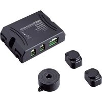
MSG-150 contains a sensor and an acoustic signal generator and is connected to a 12/24 V DC voltage supply, e.g. the cigarette lighter in a vehicle.
In addition to this, MSG-150 contains an internal relay. An external siren of signal lamp can be connected to this.
The connection terminal for the relay connection can be found on the back of the gas detector (3, page 4).
No. in
3, page 4
Description
1 Relay contact 1
2 Relay contact 2
You can operate MSG-150 in three ways:
As single device
In combination with the MS-620SI external siren
In combination with MagicSafe MS-650 or MS-620 alarm systems
7 Mounting the gas detector
7.1 Tools required
For mounting you will require the following tools:
- Measuring ruler (1 1, page 3)
- Centre punch (1 2, page 3)
Hammer (1 3, page 3) - Drill bit set (1 4, page 3)
- Drill (1 5, page 3)
Screwdriver (1 6, page 3)


Connecting the gas detector MagicSafe MSG150
7.2 Mounting the gas detector
Note the following information when selecting a location to mount the gas detector:
Note the length of the cable.
The gas detector should be mounted in the vicinity of the sleeping area at the height of the mattress.
Select a suitable installation location.

Caution!
Before making any drill holes, ensure that no electrical cables or other parts of the vehicle can be damaged by drilling.
Hold the mounting panel on the chosen location and mark the two drill holes (5, page 5).
Screw the mounting panel tight with the two screws (6, page 5).
Insert the gas detector on the mounting panel (7, page 5).
Insert the plug of the gas detector in the socket of your 12/24 V DC voltage supply.
✓ The green LED on the gas detector (8 1, page 5) flashes for approx. 10min . The sensor is then brought to the operating temperature.
When the green LED glows constantly, the gas detector is ready for operation.
8 Connecting the gas detector
8.1 As a single device
If you use the MSG-150 as a single device, you can either
- Switch it on with the 12/24V plug.
- Switch it on with the RV-AMP-SW additional switch (accessory), if there is no 12/24 V socket in the sleeping area.
Connecting the MSG-150 with a 12/24 V plug
Insert the 12 / 24V plug into a socket with a constant 12 / 24V supply.
This socket should be connected to the battery.
An acoustic signal sounds and the green LED (8 1, page 5) flashes for approx 10 minutes.
During this time the MSG-150 conducts a system test and the sensor is brought to operating temperature.

MagicSafe MSG150 Connecting the gas detector
Permanently wiring the MSG-150
If you wish to give the gas detector a permanently wired connection and switch it on with the RV-AMP-SW additional switch, please use the circuit diagram 9, page 6.
Disconnect the 12/24 V plug from the cable.
Remove around 10cm of the outer insulation on the end of the cable.
Connect the black, yellow and orange cable to the bodywork earth (terminal 31).
Connect the red cable to the output of the RV-AMP-SW additional switch.
Connect the input of the switch with a 1 A fuse to the positive battery pole.
8.2 In combination with the MS-620SI external siren
If you wish to connect the gas detector with the MS-620SI external siren, please use the circuit diagram 10, page 6.
Mounting the external siren
The external siren can be mounted in the engine compartment.
When mounting it, ensure that the installation location is
Not in an area exposed to splashing water
Not near the exhaust system
- Cannot be accessed from underneath the vehicle, to ensure that it cannot be sabotaged
Mount the external siren with the acoustic horn facing downwards.
Connecting the alarm siren
Connect the black cable of the siren to the bodywork earth (terminal 31).
Connect the red cable of the MS-620SI siren to the relay contact 2 (3 2, page 4).
Connect the relay contact 1 (3 1, page 4) to 12V continuous positive. The cable must be fused with at least a 1 A fuse.

Note:
If your vehicle does not have a 12V continuous positive cable in the mounting area, you can also connect the input to the battery via a 1 A fuse.

Connecting the gas detector MagicSafe MSG150
8.3 In combination with MS-620 or MS-650
If you wish to use the gas detector in combination with
MS-620, please use the circuit diagram 11, page 7
MS-650, please use the circuit diagram 11, page 7

Caution!
If you combine MAGIC WATCH MSG-150 with the MS-620 or MS-650 alarm system, you must configure the convenience output of the software as follows:
- MS-620: set the convenience output to "1" (see the "Programming Magic-Safe - software functions" chapter, No. 3).
- MS-650: the convenience output (see "Software settings" chapter, button 2-1) must be set to "OFF".
Disconnect the 12 / 24V plug from the cable.
Remove around 10~cm of the outer insulation on the end of the cable.
Connect the black cable to the bodywork earth (terminal 31).
Connect the yellow cable to the following cable of the external alarm system: - Blue/black cable (MS-620) - Green/red cable (MS-650)
Connect the orange cable with the brown/white cable of the external alarm system (MS-620 and MS-650).
Connect the red cable to 12 / 24V continuous positive. The cable must be fused with at least a 1 A fuse.
If the gas detector is to be switched as the main alarm on the MS-620 or MS-650 external alarm system, connect
The relay contact 1 (3 1, page 4) to the bodywork earth (terminal 31) and
The relay contact 2 (3 2, page 4) to the grey wire of the external alarm system (MS-620 or MS-650).

MagicSafe MSG150 Operating the gas detector
9 Operating the gas detector
To avoid false alarms caused by cooking, using deodorants, heavy smoking and alcohol consumption, the vehicle should be ventilated thoroughly before retiring to bed and then the gas detector should be switched on.
No. in 8, page 5
Description
1 Green LED
The green LED flashes for approx. 10 minutes after the gas detector has been connected to a voltage supply or switched on with the RV-AMP-SW auxiliary switch. While the LED is flashing, the sensor is brought to the operating temperature.
When the green LED glows constantly, the gas detector is ready for operation.
2 Orange LED:
The orange LED glows if a fault occurs.
3 Red LED (alarm)
The red LED flashes if an alarm has been triggered. In addition to this a siren sounds an alarm signal. (See also the "Alarm" chapter on page 26.)
4 Button
This button is a test button and also mutes the system.
Test button
Press this button once a month or after longer periods of disuse to check the system is functioning.
The orange and red LEDs flash and a siren sounds.
Mute switch
Press this button if you wish to switch off the sound during an alarm.
The red LED continues flashing and a brief signal sounds every 45 seconds.
Switching on MSG-150 as a single device or in combination with the MS-620SI external siren
Insert the 12 / 24V plug in a socket or switch on the MSG-150 with the RV-AMP-SW auxiliary switch.
An acoustic signal sounds and the green LED (8 1, page 5) flashes for approx 10 minutes.
During this time the MSG-150 conducts a system test and the sensor is brought to operating temperature.


Alarm MagicSafe MSG150
If an alarm occurs, an acoustic signal sounds over the internal siren and the red LED
(8 3, page 5) glows. If the MS-620SI external siren is connected, an additional acoustic signal sounds over the external siren.
To interrupt the internal alarm, press the button (8 4, page 5).
Switching on MSG-150 in combination with MS-620 or MS-650
Switch the MS-620 or MS-650 alarm system on as usual:
On the remote control for the alarm system, press
- The bottom button (MS-620)
- The grey button (MS-650)
An acoustic signal sounds and the green LED (8 1, page 5) flashes for approx 10 minutes.
During this time the MSG-150 conducts a system test and the sensor is brought to operating temperature.
If an alarm occurs, an acoustic signal sounds over the internal siren and the red LED
(8 3, page 5) glows. The internal relay sends an earth signal to the alarm input of the external alarm system. The external alarm system immediately triggers an external alarm using the vehicle indicators and the vehicle horn or the siren.
To interrupt the internal alarm, press the button (8 4, page 5).
To deactivate the external alarm, press
- The top button (MS-620) on the alarm system remote control or
- The blue button (MS-650)

10 Alarm
If an alarm is signalled, proceed as follows:
Determine the cause of the alarm immediately.
Instruct children and anybody still asleep to leave the vehicle or boat.
Open all doors and windows as quickly as possible.
Avoid striking matches or any naked flames and turn off any sources of combustion immediately.
Turn off all gas-powered devices.
Avoid causing sparks (do not use any electrical switches).
Rectify the cause or leave the vehicle or the boat.
False alarm
For your safety, the gas detector is very sensitive. For this reason the sensor also reacts to other gaseous media. Using aerosols (e.g. propellants in spray cans) or thick tobacco smoke, heavy alcohol fumes or steam arising from cooking can trigger an alarm even though no gas or anaesthetic gas is present.

MagicSafe MSG150 Troubleshooting
11 Troubleshooting
If the device is not ready for operation (the green LED does not glow), proceed as follows:
Make sure the power supply is 12 or 24VDC
If the voltage is less than this, or the voltage supply has been interrupted, the gas detector does not function.
Check the fuse in the plug, if the gas detector is connected using a 12 / 24V plug.
Checking the fuse in the 12/24 V plug
In the tip of the plug there is a fuse to protect the gas detector.
If the thin metal connection in the middle between the two metal caps is broken, the fuse is defective and must be replaced. Replacement fuses are available from customer services.

Make sure that you only use the same fuse type (5 A/250 V) in the plug. Damage to the device resulting from using inappropriate fuse types is excluded from guarantee claims under the terms of the warranty.
To replace the fuse, proceed as follows:
Pull the adapter sleeve (4 4, page 4) off of the plug.
Unscrew the screw (4 5, page 4) out of the upper half of the housing (4 1, page 4).
Carefully lift the upper half of the housing off from the lower (4 6, page 4) half.
Take out the contact pin (4 3, page 4).
Replace the defective fuse (4 2, page 4) with a new fuse that has the same rating.
Re-assemble the plug in the reverse order.
12 Maintaining and cleaning the gas detector

Caution!
Do not use sharp or hard objects for cleaning as these may damage the device.
Clean the gas detector with a soft, damp cloth from time to time.
Guarantee MagicSafe MSG150
13 Guarantee
Our general guarantee conditions apply. If the product is defective, please return it to the WAECO branch in your country (see the back of the instruction manual for the addresses) or to your specialist dealer. For repair and guarantee processing, the following documents must be sent along with the device:
A copy of the receipt with purchasing date
A reason for the claim or description of the fault
14 Disposal
Place the packaging material in the appropriate recycling waste bins wherever possible.

If you wish to finally dispose of the device, ask your local recycling centre or specialist dealer for details about how to do this in accordance with the applicable disposal regulations.
15 Technical data
Model No. MSG-150-N
Dimensions (W x H x D): 80 x 156 x 51 mm
Input voltage range: 10 V DC - 32 V DC
Power consumption: 1.3 W
Operating temperature: 0^ to +40^
Signal volume: approx. 85 dB at a distance of 3m
Protection class: IP 20
Replacement fuse: 5 A/250 V
Versions, technical modifications and delivery options reserved.
Approval

MagicSafe MSG150 Description technique
6 Description technique
RV-AMP-SW Tilleggsfilter
5 Tiltenkt bruk
Overseas + Middle East

WAECO Pacific Pty. Ltd.
1 John Duncan Court
Varsity Lakes QLD 4227
+61755076000
+61755076001
Mail: sales@waeco.com.au

Domatic Switzerland AG
Riedackerstrasse 7a
CH-8153 Rümlang (Zürich)
+41448187171
+41448187191
Mail: info@waeco.ch
Dometic Norway AS
Leif Weldingsvei 16
N-3208 Sandefjord
+4733428450
+4733428459
Mail: firmapost@waeco.no

WAECO Impex Ltd.
Suites 3210-12·32/F·Tower 2
The Gateway 25 Canton Road,
Tsim Sha Tsui, Kowloon
Hong Kong
+85224632750
+852 24639067
Mail: info@waeco.com.hk

Domatic Denmark A/S
Tvaervej 2
DK-6640 Lunderskov
+4575585966
+4575586307
Mail: info@waeco.dk
Domatic Benelux B.V.
Ecustraat 3
NL-4879 NP Etten-Leur
+31765029000
+31765029090
Mail: info@dometic.nl

WAECO Impex Ltd.
Taipei Office
2 FL-3 · No. 56 Tunhua South Rd, Sec 2
Taipei 106, Taiwan
+886227014090
+886227060119
Mail: marketing@waeco.com.tw

Dometic Spain S.L.
Cam del Mig, 106
Poligono Industrial Les Corts
E-08349 Cabrera de Mar
(Barcelona)
+34937502277
+34937500552
Mail: info@waeco.es

#
Gustaf Melins gata 7
S-42131 Västra Frolunda
(Göteborg)
+46317341100
+46317341101
Mail: info@waeco.se

WAECOMiddle East FZCO
R/A 8, SD 6
Jebel Ali, Dubai
+97148833858
+97148833868
Mail: waeco@emirates.net.ae