
MagicWatch MW150 - Parking assist WAECO - Free user manual and instructions
Find the device manual for free MagicWatch MW150 WAECO in PDF.

| Product type | Ultrasonic parking aid |
| Brand | Waeco |
| Model | MagicWatch MW150 |
| Power supply | 10 – 15 V (DC) |
| Power consumption | 35 mA (standby) / 60 mA (active signal) |
| Detection range | Up to 1.2 m |
| Ultrasonic frequency | 38.5 kHz |
| Operating temperature | -20 °C to +70 °C |
| Speaker volume | 100 dB (intervals of 10 cm) |
| Number of sensors | 2 |
| Sensor type | Self-adhesive ultrasonic |
| Warning signal | Audible (piezo speaker) with slow, medium and fast sequences |
| Mounting method | Sensors glued on or above the bumper, speaker glued on the trunk lid |
| Cable length | To be adapted according to the vehicle (not specified) |
| Maintenance and cleaning | Clean the sensors with a damp cloth; do not use hard or sharp objects |
| Safety | Disconnect the battery before any electrical work; follow the mounting instructions |
| Intended use | Reverse parking aid for passenger vehicles; does not replace caution |
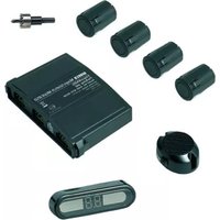
| Delivery contents | Control electronics, 2 sensors, piezo speaker, mounting hardware, manual |
| LED tail light compatibility | May cause malfunctions; check with the manufacturer |
| Warranty | Not specified |
Frequently Asked Questions - MagicWatch MW150 WAECO
User questions about MagicWatch MW150 WAECO
0 question about this device. Answer the ones you know or ask your own.
Ask a new question about this device
Download the instructions for your Parking assist in PDF format for free! Find your manual MagicWatch MW150 - WAECO and take your electronic device back in hand. On this page are published all the documents necessary for the use of your device. MagicWatch MW150 by WAECO.
USER MANUAL MagicWatch MW150 WAECO
natural_image
Technical line drawing of a device with ports and wiring, no text or symbols presentMagicWatch MW150
D 7 Ein park hil f
Installation and Operating Manual
We will be happy to provide you with further information about WAECO products. Please order our free catalogue with no obligation to buy on our homepage: www.waeco.com
F
natural_image
Pure geometric diagram with concentric circles and radial lines, no text or symbols presentMagicWatch MW150
natural_image
Technical line drawing of a welding process with arrows indicating motion (no text or symbols)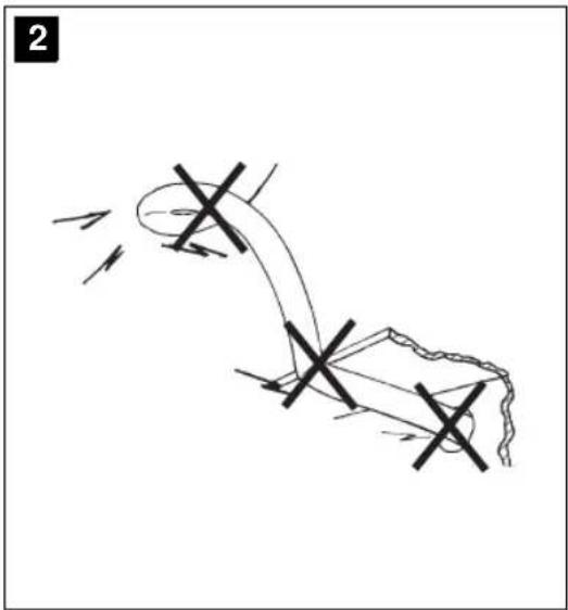
natural_image
Diagram of a mechanical or electrical component with directional arrows and cross marks, no readable text or symbols present.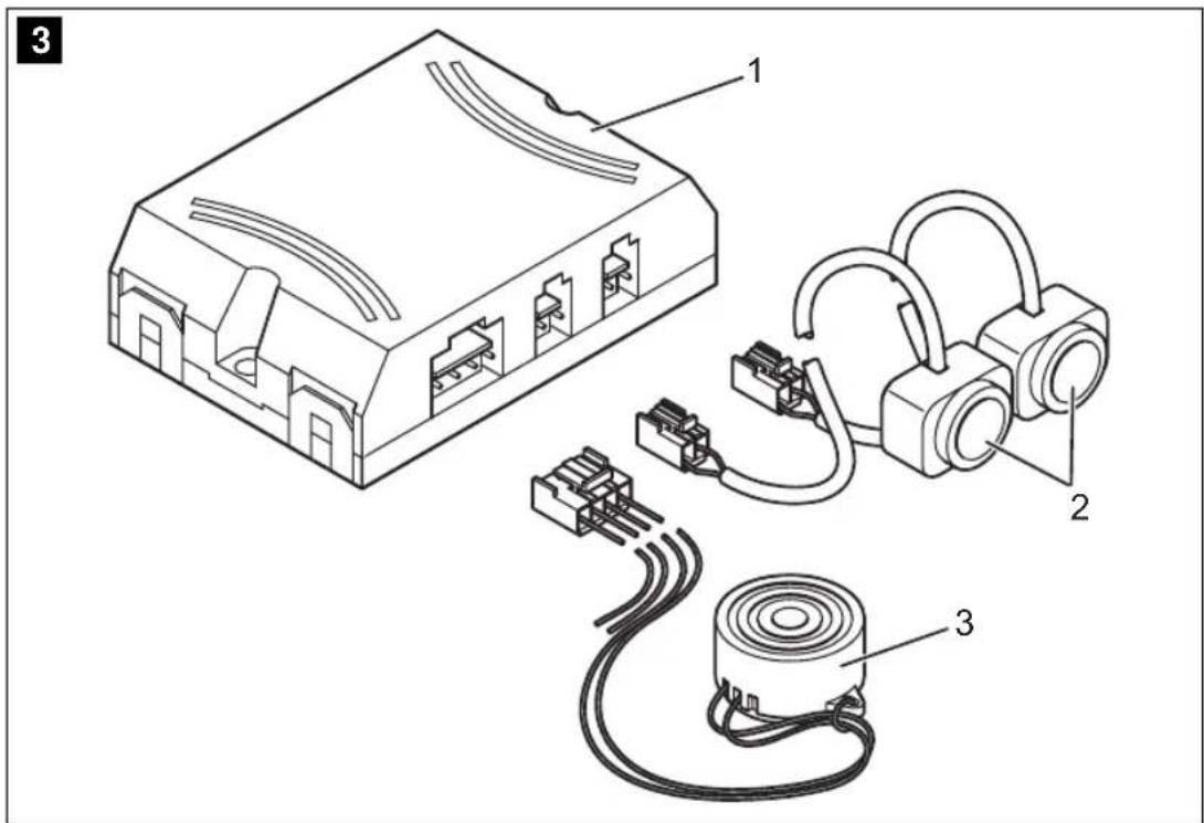


MagicWatch MW150
4
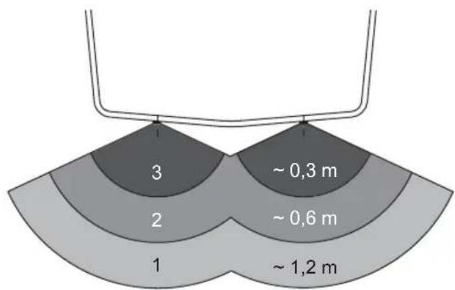
pie
| Segment | Value | |---|---| | 1 | ~1.2 m | | 2 | ~0.6 m | | 3 | ~0.3 m |5
natural_image
Line drawing of a car emitting a radiation beam, showing no text or symbols6
natural_image
Side view line drawing of a car emitting a radiation beam from a detector labeled A, B, and C (no text or symbols on the diagram itself)7


MagicWatch MW150
8
9
10
natural_image
Line drawing of a vehicle's rear view showing the roof and side legs with 90-degree angles marked (no text or symbols beyond basic geometry)m = 311
natural_image
Technical line drawing of a mechanical component with an inset close-up showing a cylindrical component (no text or symbols)MagicWatch MW150
natural_image
Diagram of an electronic device with two connected earbuds (no text or symbols)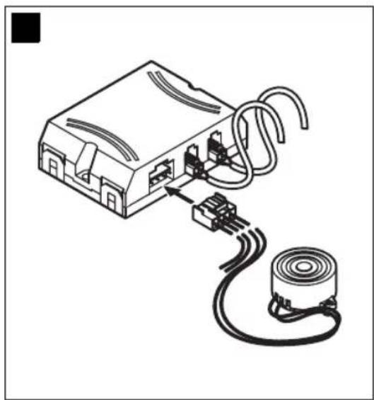
natural_image
Diagram of an electronic device with a coiled cable and motor, showing internal components connected to a cylindrical component (no text or symbols present)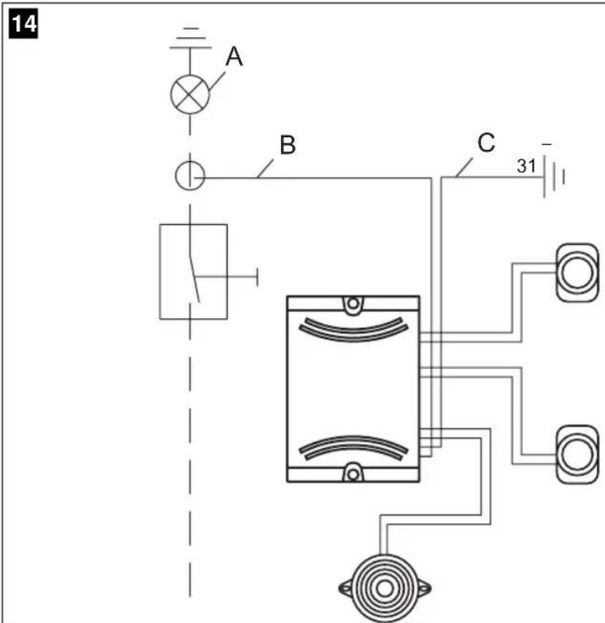


MagicWatch MW150
natural_image
Pure geometric diagram with concentric circles and crosshairs, no text or symbols presentMagicWatch MW150 Lieferumfang
natural_image
Pure geometric diagram with concentric circles and radial lines, no text or symbols presentMagicWatch MW150 MagicWatch montieren
natural_image
Pure geometric diagram with crosshair and circular shapes (no text or symbols)MagicWatch MW150 MagicWatch montieren
Please read this manual carefully before starting the machine. Keep it in a safe place for future reference. If the system is resold, this manual must be handed over to the purchaser along with the system.
1 Table of Contents
2 Information for using the instructions....21
3 Safety and installation instructions....22
4 Scope of delivery 24
5 Proper Use....25
6 Technical description 25
7 Assembling MagicWatch 27
8 Testing the Operation 30
9 Using MagicWatch....31
10 Cleaning and Caring MagicWatch 32
11 Trouble shooting 32
12 Disposal 32
13 Technical Data. 32
2 Information for using the instructions

Warning!
Safety precaution: Failure to observe this instruction can damage the device and impair its function.
Caution!
Safety precaution, relating to a danger from electrical current or voltage. Failure to observe this instruction can damage the device and impair its function.

Note
Supplementary information for operating the device.
Safety and installation instructions MagicWatch MW150
▶ Action: this symbol indicates that you need to do something. The required action is described step-by-step.
√This symbol indicates the result of an action.
Please observe the following safety instructions.
3 Safety and installation instructions
Please obey the safety rules and regulations given by the car manufacturer.
Warning!
Because of the risk of short circuits, always disconnect the negative pole of the battery before starting work.
In case of vehicles with a supplementary battery, also disconnect this negative pole.
Warning!
Improper cable connections may result in short circuits which can cause
- cable fires,
– triggering of the airbag,
– damage to electronic control equipment,
– failure of electrical functions (indicators, brake lights, horn, ignition, lights).
Therefore please observe the following instructions:
- When working at the following cables use only insulated cable brackets, connector plugs and tabs.
- 30 (input from battery plus direct)
- 15 (switched plus, behind battery)
- 31 (return cable from battery, neutral)
Do not use any lustre terminals.
- For connection the cables with cable brackets, plugs or tabs, use crimping pliers.


natural_image
Pure geometric diagram with crosshair and circular shapes without any text or symbolsMagicWatch MW150 Safety and installation instructions
● For cable connections to 31 (earth) attach the cable
– with a bracket and toothed washer to an earthing screw or
– on the vehicle using a bracket, metal screw and toothed washer.
Always ensure a good earthing connection!
On disconnecting the negative pole of the battery, all the volatile memories of the comfort electronics will lose their stored data.
- Depending on the vehicle's equipment, the following data may have to be re-entered:
- Radio code
- Clock
- Timer
- Board computer
- Seat position
Instruction on how to reset these can be found in the relevant operating instructions.
Please observe the following instructions during the assembly:
- Fix those components of the MagicWatch installed inside the vehicle securely, so that they cannot come loose and injure the vehicle's passengers under any circumstances.
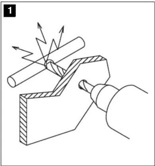
- To avoid damages, always ensure that there is enough clearance for the drill bit to emerge (see fig. 1, page 3). Every drill hole must be debarred and reared with a rust proofing agent.
- Whenever possible, do not mount the sensors directly above the end of the exhaust. Otherwise errors in the display may result.
Please observe the following instructions during work on electrical parts:
- For checking the voltage of electric cables, use only a diode test lamp or a voltmeter.
Test lamps which light up take too much current and the vehicle electronics may be damaged. - When laying the electric cables, always ensure that they
– are not sharply bent or twisted, - will not rub against edges,
- are always equipped with protection tape or else when inserted through sharp edged apertures (see fig. 2, page 3).
● Insulate the cable with insulating tape, e. g. for existing cables.


Scope of delivery MagicWatch MW150
- Protect the connecting cable from wearing by means of cable bushing sleeve.
Please observe the following instructions in particular:
- Installing the reversing distance sensor can cause problems on vehicles with LED tail lights. Please consult the manufacturer of your vehicle.
- Observe the valid legal prescription.
● The sensors may cover any signal lamps. - When reversing drive so as to avoid endangering other road users.
● Critical obstacles may not be identified or may only be identified inaccurately due to physical reflection properties.
● MagicWatch is meant as an additional help, that means the device does not relieve you of your particular duty to be cautious when reversing.
● MagicWatch is only possible by a slowly reversing (ranging speed). - Remove snow, ice or dirt from the sensors in order to avoid malfunctions.
4 Scope of delivery
No. in fig. 3, page 3 Quantity Description Article No.
1 1 Electronic box MWZ-150
2 2 Ultrasonic sensors MWS-150
3 1 Piezo-speaker MWL-150
- 1 Fastening material -
-- Installation and Operating Manual -


natural_image
Pure geometric diagram with crosshair and circular shapes without any text or symbolsMagicWatch MW150 Proper Use
5 Proper Use
MagicWatch is reverse supervisory unit based on ultrasonic. It checks the place behind the vehicle during reversing procedures and warns acoustically against obstacles, which are detected through the device.
MagicWatch provides an assistance when reversing, however, it does not relieve you from your special caution required when reversing.
MagicWatch has been laid out for assembling in passenger cars.
6 Technical description
6.1 Function specification
MagicWatch consists of two ultrasonic sensors, one control unit and one piezo-speaker. The assembling of the piezo-speaker takes place near the hat rack or luggage compartment covering.
The measurement of distance is based upon the echo-transit-time principle. Both sensors continuously emit ultrasonic signal pulses while reversing.
The sensors operate both as transmitters and as receivers, which receive again the beamed and reflected ultrasonic signals from possible obstacles. The distance from the obstacle is evaluated through the transit time of the ultrasonic signals and is indicated by sequence of pulse tones of the piezo-speaker. The closer the obstacle, the faster the sequence of pulse tones.
6.2 Detection range
The detection range of MagicWatch is split into three zones (see fig. 4, page 4).
- Zone 1
This zone is the first limit range: small or badly reflecting objects may not be detected.
- Zone 2
In this zone nearly each obstacle is indicated.
- Zone 3
In this zone nearly each obstacle is indicated, but objects can get into the blind angle of the sensors


Technical description MagicWatch MW150

Situations may occur where MagicWatch does not detect objects or indicate the shortest distance due to the physical structure of the objects.
Please note the following four examples concerning this.
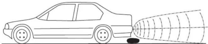
Example 1 (see fig. 5, page 4)
Objects, which from the beginning are not in the detection range of the sensors, cannot be perceived.
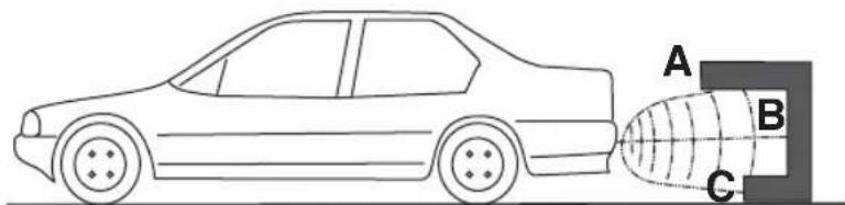
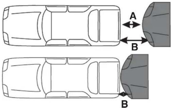
Example 2 (see fig. 6, page 4)
In the case of cleaved objects, the shortest distance will not necessarily be indicated. For example A will not be indicated but only B or C.
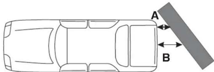
Example 3 (see fig. 7, page 4)
In the case of diagonal obstacles the shortest distance A will be indicated.
Example 4 (see fig. 8, page 5)
In the illustrated case MagicWatch will indicate the distance A. If the vehicle comes closer to the other one, the sensor signal first goes over to the stop range and then the distance A gets into the blind angle and the device indicates the distance to point B.

Caution!
As shown in these four examples, situations may occur where the device does not indicate an object or not the shortest distance.
The device does not relieve you from your duty to be cautious when reversing. You should always back with extreme care.
If an object gets into the non-controlled area of the sensors, MagicWatch automatically indicates the distance to the next object. This means, the piezo-speaker will then switch over from the high to the medium sequence of pulse tones.
In this case always stop the vehicle immediately and check the situation.
MagicWatch MW150 Assembling MagicWatch
7 Assembling MagicWatch
7.1 Tools required
The following tools are needed for installation:
- set of bits
- electric drill
- screwdrivers
- set of spanners
The following tools are needed for making the electrical connections:
- diode test lamp or voltmeter
- insulating tape
- maybe rubber bushings
Depending on individual circumstances, you may also need other screws, bolts, nuts, washers, metal screws and cable connectors.
7.2 Assembling Sensors

To assure a proper operation it is important to fix the sensors with the correct inclination.
Are the sensors turned to the ground, it indicates the surface of the ground like an obstacle. Are the sensors turned to high, obstacles may not be detected.
Consider the following specifications when assembling:
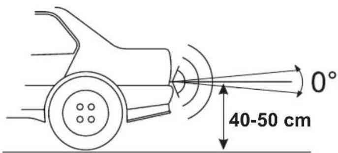
● The maximum detection distance is approx. 1.2 m.
- To protect the edges of the vehicle (indication lights) please mount the sensors within 0.3 m from the edge.
- The sensors should be mounted aprox. 40 – 50 cm away from the bottom (see fig. 9, page 5).
- The horizontal alignment of the sensors should be 0^ from the centerline (see fig. 9, page 5).
Assembling MagicWatch MagicWatch MW150
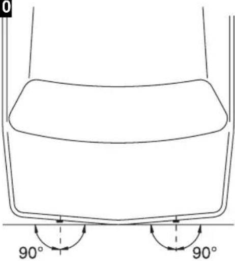
- The vertical alignment of the sensors should be 90^ from the cross axis of the vehicle (see fig. 10, page 5).
Assemble as follows:
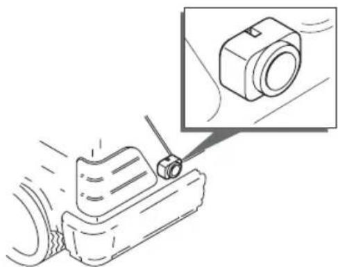
▶ Please locate the sensor that way it is installed perpendicular to the ground (see fig. 11, page 5).

Note!
The adhesion surfaces must be dry, clean and free of grease.
▶Strip the protective film and glue on the sensors.
7.3 Laying the Sensor Cables
If you lay the cables take care, that the cables
● are not buckled or twisted,
- do not abrase at edges,
● are not laid through sharp edged lead troughs without protection.

Caution!
Before performing any boring or cutouts ensure that no electrical wiring or other parts of the vehicle can be damaged by drilling, cutting and filing.
Protect each opening at the car's shell against intrusion of water, e. g. by using sealing compound for cable and lead through.
▶Laying the sensor cables, use original rubber bungs if possible. In case there are not any available, drill an appropriate hole of ∅ 13 mm and set in a rubber bushing.

Note!
Pass the sensor cable connectors through the bushing before installing them in the car body.
▶Lay the connecting cable of the sensors in the luggage compartment so that they cannot be damaged (e. g. due to impact of stones).
▶Attach the connecting cable meticulously behind the bumper.


natural_image
Pure geometric diagram with crosshair and circular shapes without any text or symbolsMagicWatch MW150 Assembling MagicWatch
7.4 Mounting the Control Unit
Please consider the following instructions for determining the right location:
- Consider the cable length of sensors.
● Luggage or other objects may not damage the control unit.
▶Mount the control unit on a suitable place inside the luggage compartment.

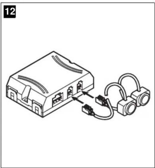
The jack's polarity cannot be reversed: You can plug it onto the connector only in one direction.
▶Connect the jacks of the sensor cables to the connectors of the control unit (see fig. 12, page 6).
7.5 Mounting the speaker on the hat rack
The piezo-speaker should be glued or mounted on a suitable place on the hat rack.
Please consider the following instructions when determining the mounting position:
- Consider the cable length of the speaker.
Take into account, that for cars with big rear flaps the luggage deck will swing up.
● The piezo-speaker must not be covered or damaged by loose parts put on the hat rack.
▶Lay the cable of the speaker to the control unit and plug the jack onto the connector of the control unit (see fig. 13, page 6).
Remove the protective liner from the adhesive tape and glue on the piezo-speaker.


Testing the Operation MagicWatch MW150
7.6 Connecting the Control unit
Caution!
Take care for correct polarity.

For some vehicles the reversing lamp operates only, if switch is on. In this case turn on the ignition for depending the supply and the negative line.
▶ Connect the red wire (see fig. 12 B, page 6) of the control unit onto the supply line (+) of the reversing lamp (see fig. 12 A).
Connect the black wire (see fig. 12 C, page 6) of the control unit onto the negative line (−) or onto earth (car body).
8 Testing the Operation
Test the operation as follows:
▶Switch-on the ignition and put the vehicle into reverse.
The reversing distance sensor MW-150 lacks a visual display, but is equipped with an acoustic signal transmitter only. Therefore be careful when you use it first time and get familiar with the different tone sequences.
| Zone | Description (see fig. 4, page 4) | Affiliated tone sequences |
| 1 | Starting from a distance of approx. 1.2 m, obstacles will be detected and indicated by the piezo-speaker with a slow sequence of pulse tones. | Bi Bi Bi Bi |
| 2 | At a distance range from approx. 0.6 m MagicWatch switches over to medium sequence of pulse tones. | Bi Bi Bi Bi Bi Bi |
MagicWatch MW150 Using MagicWatch
| Zone | Description (see fig. 4, page 4) | Affiliated tone sequences |
| 3 At | a distance range of approx. 0.3 m or less, the MagicWatch switches over to the high sequence of pulse tones. If this area is reached, the vehicle should be stopped in any case.Otherwise the vehicle or the obstacle can be damaged. | Bi Bi Bi Bi Bi Bi Bi Bi Bi |

Within zone 3 it can happen, that obstacles are no longer recognized as they are out of the detection range of the sensors.
9 Using MagicWatch
MagicWatch is automatically activated by putting the vehicle into reverse, if the ignition is switched-on or the engine is running.
As soon as an obstacle is detected, a regular repetitive pulse tone sounds. Driving the vehicle backwards, dependent on the detection zone (see chapter “Testing the Operation” on page 30), the sequence of pulse tones will increase and herewith indicates the actual distance range.
Using the reverse distance sensor for the first time, please take special care and get familiar with the different sequences of pulse tones.

Caution!
Stop the vehicle immediately if following situation occurs while manoeuvring:
When manoeuvring backwards, the decreasing distance to an obstacle is indicated by e.g. switching from slow to medium sequence of pulse tones. Suddenly the unit may jump again into the slow sequence of pulse tones or even does not indicate the obstacle any longer.
This means, that the obstacle is no longer within the detectable area. In such a case stop the vehicle and check the situation.
Cleaning and Caring MagicWatch MagicWatch MW150
10 Cleaning and Caring MagicWatch

Caution!
Never use sharp or hard detergents as they can damage the sensors.
▶Clean the sensors with a damp cloth from time to time.
11 Trouble shooting
The unit shows no function
The connecting lines to the reversing lamps do not have any contact or are interchanged.
The jack of the piezo-speaker is not or is not correctly fitted to the control unit.
The jacks of the sensors are not or are not correctly fitted to the control unit.
▶ Check the jacks and plug them if necessary until they catch.
12 Disposal
▶Place the packaging material in the appropriate recycling waste bins wherever possible.
If you wish to finally dispose of the MagicWatch, ask your local recycling centre or specialist dealer for details about how to do this in accordance with the applicable disposal regulations.
13 Technical Data
Detection range: up to 1.2 m
Ultrasonic frequency: 38.5 kHz
Supply voltage: 10 – 15 Volts
Current consumption: 35 mA (Standby mode)
60 mA (Signal operation)
Working temperature: -20^ through +70^
Loudness of the piezo-speaker: 100 dB (at 10 cm distance)


natural_image
Pure geometric diagram with crosshair and circular shapes without any text or symbolsMagicWatch MW150
natural_image
Pure geometric diagram with crosshair and circular shapes without any text or symbolsDescription technique MagicWatch MW150
6 Description technique
MagicWatch MW150 Description technique
natural_image
Pure geometric diagram with crosshair and circular shapes without any text or symbolsMagicWatch MW150 Utiliser MagicWatch
9 Utiliser MagicWatch
natural_image
Pure geometric diagram with crosshair and circular shapes without any text or symbolsnatural_image
Pure geometric diagram with crosshair and circular shapes without any text or symbolsMagicWatch MW150
natural_image
Pure geometric diagram with crosshair and circular shapes without any text or symbolsnatural_image
Pure geometric diagram with crosshair and circular shapes without any text or symbolsMagicWatch MW150 Omvang van de levering
natural_image
Pure geometric diagram with crosshair and circular shapes without any text or symbolsMagicWatch MW150 MagicWatch monteren
natural_image
Pure geometric diagram with crosshair and circular shapes without any text or symbolsMagicWatch MW150
natural_image
Pure geometric diagram with crosshair and circular shapes (no text or symbols)MagicWatch MW150 Leveringsomfang
4 Leveringsomfang
Nr. på
fig. 3, side 3
natural_image
Pure geometric diagram with crosshair and circular shapes without any text or symbolsMagicWatch MW150 Montering af MagicWatch

Vigtigt!
natural_image
Pure geometric diagram with crosshair and circular shapes (no text or symbols)MagicWatch MW150 Montera MagicWatch
7.2 Montera sensorerna

natural_image
Pure geometric diagram with crosshair and circular shapes without any text or symbolsMagicWatch MW150 Montera MagicWatch

natural_image
Pure geometric diagram with crosshair and circular shapes without any text or symbolsMagicWatch MW150 Leveringsomfang
natural_image
Pure geometric diagram with crosshair and circular shapes (no text or symbols)natural_image
Pure geometric diagram with crosshair and circular shapes (no text or symbols)natural_image
Pure geometric diagram with crosshair and circular shapes without any text or symbolsMagicWatch MW150 MagicWatch -laitteen asentaminen
F-60230 Chambly (France)
Fon: +33 1 30282020
Fax: +33 1 30282010
E-Mail: info@waeco.fr

WAECO Finland OY
Mestarintie 4
FIN-01730 Vantaa
Fon: +358 20 7413220
Fax: +358 9 7593700
E-Mail: waeco@waeco.fi

WAECO Italcold SRL
Roman Hill Business Park
UK-Broadmayne
Fon: +44 1305 854000
Fax: +44 1305 854288
E-Mail: sales@waeco.co.uk
Overseas + Middle East

WAECO Pacific Pty. Ltd.
1 John Duncan Court
Varsity Lakes QLD 4227
Fon: +61 7 55076000
Fax: +61 7 55221003
E-Mail: sales@waeco.com.au

WAECO Impex Ltd.
Headquarters
Suites 3210-12 · 32/F · Tower 2
The Gateway · 25 Canton Road
Tsim Sha Tsui · Kowloon
Hong Kong
Fon: +852 2 4632750
Fax: +8 52 24639067
E-Mail: info@waeco.com.hk

WAECO Impex Ltd.
Taipei Office
2 FL-3 · No. 56 Tunhua South Rd, Sec 2
Taipei 106, Taiwan
Fon: +886 2 27014090
Fax: +886 2 27060119
E-Mail: marketing@waeco.com.tw

WAECO Middle East FZCO
R/A 8, SD 6
Jebel Ali, Dubai
Fon: +971 4 8833858
Fax: +971 4 8833868
E-Mail: waeco@emirates.net.ae

WAECO USA, Inc.
8 Heritage Park Road
Clinton, CT 06413
Fon: +1 860 6644911
Fax: +1 860 6644912
E-Mail: customercare@waecousa.com


- MagicWatch MW150
- F
- MagicWatch MW150 Lieferumfang
- MagicWatch MW150 MagicWatch montieren
- Table of Contents
- Information for using the instructions
- Warning!
- Caution!
- Note
- Safety and installation instructions
- MagicWatch MW150 Safety and installation instructions
- Scope of delivery MagicWatch MW150
- Scope of delivery
- No. in fig. 3, page 3 Quantity Description Article No.
- Proper Use
- Technical description
- Function specification
- Detection range
- - Zone 1
- - Zone 2
- - Zone 3
- Technical description MagicWatch MW150
- Example 1 (see fig. 5, page 4)
- Example 2 (see fig. 6, page 4)
- Example 3 (see fig. 7, page 4)
- Example 4 (see fig. 8, page 5)
- MagicWatch MW150 Assembling MagicWatch
- Assembling MagicWatch
- Tools required
- Assembling Sensors
- Assembling MagicWatch MagicWatch MW150
- Note!
- Laying the Sensor Cables
- Mounting the Control Unit
- Mounting the speaker on the hat rack
- Connecting the Control unit
- Testing the Operation
- Using MagicWatch
- Cleaning and Caring MagicWatch
- Trouble shooting
- The unit shows no function
- Disposal
- Technical Data
- Description technique
- MagicWatch MW150 Description technique
- MagicWatch MW150 Utiliser MagicWatch
- Utiliser MagicWatch
- MagicWatch MW150 Omvang van de levering
- MagicWatch MW150 MagicWatch monteren
- Leveringsomfang
- Nr. på
- fig. 3, side 3
- MagicWatch MW150 Montering af MagicWatch
- Vigtigt!
- MagicWatch MW150 Montera MagicWatch
- Montera sensorerna
- MagicWatch MW150 Leveringsomfang
- MagicWatch MW150 MagicWatch -laitteen asentaminen
- Overseas + Middle East
Brand : WAECO
Model : MagicWatch MW150
Category : Parking assist