
MagicWatch MWE850 - Parking assist WAECO - Free user manual and instructions
Find the device manual for free MagicWatch MWE850 WAECO in PDF.
| Product type | Ultrasonic parking aid (reversing radar) |
| Brand | Waeco |
| Model | MagicWatch MWE850 |
| Detection range | Up to 1.5 m |
| Ultrasound frequency | 40 kHz |
| Power supply | 11 – 27 V DC |
| Power consumption | 40 mA (standby), 250 mA (signal) |
| Operating temperature | -20 °C to +70 °C |
| Piezo speaker volume | 100 dB at 10 cm |
| Number of sensors | 4 |
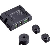
| Supplied components | Control unit, 4 ultrasonic sensors, 1 display, 1 piezo speaker, extension cables, 22.5 mm hole saw |
| Main functions | Rear obstacle detection, audible (beeps) and visual (LED) warning, distance indication in 10 cm increments, DSM (Digital Signal Memory) function to ignore small fixed objects |
| Installation | Mounting sensors in the bumper (22.5 mm holes), attaching display on dashboard or window, connection to reverse light |
| Repairability | Replacement of sensors without removing bumper (connection plug behind sensor) |
| Painting sensors | Possible, recommended by a specialized workshop |
| Maintenance and cleaning | Clean sensors with a damp cloth; do not use sharp or hard objects |
| Safety | Does not replace driver's caution; only reverse slowly; stop vehicle if audible signal changes suddenly |
| Certifications | E13 |
Frequently Asked Questions - MagicWatch MWE850 WAECO
User questions about MagicWatch MWE850 WAECO
0 question about this device. Answer the ones you know or ask your own.
Ask a new question about this device
Download the instructions for your Parking assist in PDF format for free! Find your manual MagicWatch MWE850 - WAECO and take your electronic device back in hand. On this page are published all the documents necessary for the use of your device. MagicWatch MWE850 by WAECO.
USER MANUAL MagicWatch MWE850 WAECO
natural_image
Technical line drawing of electronic devices including a network switch, connector, and smart speaker (no text or symbols present)MagicWatch MWE850
D 1 0 E i n p a r k h i l f
Installation and Operating Manual
We will be happy to provide you with further information about WAECO products. Please order our free catalogue with no obligation to buy on our homepage: www.waeco.com
F
natural_image
Technical line drawing of a welding process with arrows indicating motion (no text or symbols)
natural_image
Diagram of a mechanical or electrical component with directional arrows and cross marks, no readable text or symbols present.
MagicWatch MWE850


natural_image
Line drawing of a car emitting a radiation beam, no text or symbols present

MagicWatch MWE850


MagicWatch MWE850
14

natural_image
Line drawing of a car interior showing dashboard, steering wheel, and dashboard controls (no text or symbols)
15
natural_image
Line drawing of a car backseat with seatbelt and rearview mirror (no text or symbols)MagicWatch MWE850


MagicWatch MWE850
20

natural_image
Pure geometric diagram with crosshair and circular shapes (no text or symbols)natural_image
Pure geometric diagram with concentric circles and radial lines, no text or symbols presentMagicWatch MWE850 MWE850 montieren
natural_image
Pure geometric diagram with crosshair and circular shapes without any text or symbolsMagicWatch MWE850 MWE850 montieren

Hinweis!
Please read this manual carefully before installing and starting up and store it in a safe place. If the system is resold, this instruction manual must be handed over to the purchaser along with the device.
Contents
1 Notes on using the instruction manual. 31
2 Safety and installation instructions....31
3 Scope of delivery 34
4 Proper use 35
5 Technical description 35
6 Installing MWE850 38
7 Testing functions 44
8 Using MWE850 45
9 Maintaining and cleaning MWE850 45
10 Searching for errors 46
11 Guarantee 46
12 Disposal 47
13 Technical data 47
MagicWatch MWE850 Notes on using the instruction manual
1 Notes on using the instruction manual

Caution!
Safety instruction: failure to observe this instruction can cause material damage and impair the function of the device.

Caution!
Safety instruction relating to a danger from electrical current or voltage. Failure to observe this instruction can cause material damage or personal injury and impair the function of the device.

Note
Supplementary information for operating the device.
▶ Action: this symbol indicates that you need to do something. The required action is described step-by-step.
√This symbol indicates the result of an action.
Please observe the following safety instructions.
2 Safety and installation instructions
Please observe the prescribed safety instructions and stipulations from the vehicle manufacturer and service workshops.

Caution!
WAECO International will not be held liable for claims for damage resulting from the following:
- Installation errors
– Damage to the device resulting from mechanical influences and overvoltage
– Alterations to the device made without the explicit permission from WAECO International
– Usage for purposes other than those described in the installation manual.


Safety and installation instructions MagicWatch MWE850

Warning!
To prevent short circuits, always disconnect the negative terminal of the vehicle's electrical system before working on it.
If the vehicle has an additional battery, its negative terminal should also be disconnected.
Warning!
Insufficient supply line connections could result in short circuits which
- Cause cable fires
- Trigger the airbags
– Damage electronic control devices - Cause electric functions to fail (indicators, brake light, horn, ignition, light).
Please observe the following instructions:
- When working on the following supply lines, only use insulated cable lugs, plugs and tab sleeves.
- 30 (direct supply from positive battery terminal),
- 15 (connected positive terminal, behind the battery),
- 31 (return line from the battery, earth).
Do not use porcelain insulating clamps.
- Use a crimping tool (see fig. 1.7, page 3) to connect the cables.
● When connecting to supply line 31 (earth)
- Screw the cable to the cable lug and gear disc to the vehicle's earth bolt or
- With a cable lug and a self-tapping screw to the bodywork sheet metal.
Ensure that there is a good earth connection.


natural_image
Pure geometric diagram with crosshair and circular shapes (no text or symbols)MagicWatch MWE850 Safety and installation instructions
When the negative terminal of the battery is disconnected, all volatile memories in the convenience electronics lose the stored data.
● The following data must be set again, depending on vehicle equipment:
- Radio code
- Vehicle clock
- Timer
- On-board computer
- Seat position
You can find instructions for making these settings in the appropriate operating instructions.
Observe the following instructions during installation:
- Secure the parts of the MWE850 system installed in the vehicle in such a way that they cannot become loose under any circumstances (sudden braking, accidents) and cause injuries to the occupants of the vehicle.
- To prevent damage, when drilling ensure that there is sufficient room for the drill head to emerge once the hole has been made (see fig. 2, page 4).
Observe the following instructions when working with electrical parts:
- When testing the voltage in electrical cables, only use a diode test lamp (see fig. 1.5, page 3) or a voltmeter (see fig. 1.6, page 3).
Test lamps with an illuminant (see fig. 1.9, page 3) take up voltages which are too high and which can damage the vehicle's electronic system.
- When making electrical connections, ensure that
– They are not kinked or twisted
– They do not rub on edges
- They are not laid in sharp edged ducts without protection (see fig. 3, page 4).
● Insulate all connections.
- Secure the cables against mechanical wear with cable binders or insulating tape, for example to existing cables.
Scope of delivery MagicWatch MWE850
Please observe the following instructions in particular:
- Installing the reversing distance sensor can cause problems on vehicles with LED tail lights.
Please consult the manufacturer of your vehicle. - Whenever possible, do not mount the sensors directly above the end of the exhaust. Otherwise errors in the display may result.
- Observe the applicable legal regulations.
● The sensors may not cover signal lamps. - When reversing, make sure no other road users can be injured.
● Physical reflection properties mean you may not be able to recognise critical obstacles.
● MWE850 is designed merely as an additional aid, which means it does not release you of the duty of taking due care when reversing.
● MWE850 can only provide a warning in time if you reverse slowly (at parking speed). - Remove any snow, ice or dirt from the sensors so that the function is not impaired.
3 Scope of delivery
No. in fig. 4, page 4 Quantity Description Item number
1 1 Control electronics MWZ-850
2 4 Ultrasonic sensors MWSE-2
1 1 Control electronics MWZ-850 2 4 Ultrasonic sensors MWSE-2
3 1 D i s p l
4 1 Piezoelectronic speaker MWL-2
5 1 Display extension cable MWCD-2
6 1 Speaker extension cable MWLVC-1
7 4 Sensor extension cable MWCC-2
- 1 Core bit (22.5 mm)
4 1 Piezoelectronic speaker MWL-2 5 1 Display extension cable MWCD-2 6 1 Speaker extension cable MWLVC-1 7 4 Sensor extension cable MWCC-2 – 1 Core bit (22.5 mm)

Note
Use the cardboard packaging of the sensors as a painting aid.
MagicWatch MWE850 Proper use
4 Proper use
MagicWatch MWE850 (item number: MWE-850-4DSM) is an ultrasonic reverse warning system. When reversing, it monitors the space behind the vehicle and provides an audible and visible warning signal for any obstacles it detects.
Since MWE850 is designed merely as an additional aid for reversing, it does not relieve you of the duty to take proper care when reversing.
MWE850 is designed for installation in cars.
5 Technical description
5.1 Functional description
MagicWatch MWE850 consists of four built-in sensors, a display for visual warning signals, and a piezoelectronic speaker for audible warning signals. The piezoelectronc speaker is fitted on the parcel shelf or boot cover. The display can be mounted on the dashboard, on the rear view mirror on the windscreen or on the boot cover.
It measures distances based on the echo time principle. The four sensors constantly emit ultrasonic signals when you reverse.
The sensors contain both transmitters and receivers, and capture any ultrasonic signals reflected by obstacles. The distance to the obstacle is calculated using the echo time, and signalled by the speaker using a sequence of impulse tones. The closer the obstacle approaches, the faster the succession of warning tones.
The DSM (digital signal memory) function creates a space profile during the measurement, which records any small fixed objects (such as trailer couplings). This means these are not signalled as obstacles. The system only signals an obstacle when the space profile changes.
The display signals the position of the obstacle using two LEDs. A numerical display shows the distance in 10 cm increments.
The sensors are installed on the bumper. The sensors may be painted. WAECO recommends having the sensors painted by a specialist workshop.
Since the sensors are equipped with their own amplifiers, you can extend the connection between the sensors and the controller to up to 10 m.


natural_image
Three abstract geometric symbols: crosshair, circular pattern, and perpendicular lines (no text or labels)Technical description MagicWatch MWE850

Only use WAECO cables.
Otherwise, proper operation cannot be guaranteed.
Defective sensors can be replaced without removing the bumper. There is a plug connector just behind the sensor for this.
5.2 Detection range
The detection range of MWE850 is divided into three zones (see fig. 5, page 5):
- Zone 1
This zone is the first limit range. Small or objects with poor reflective characteristics are sometimes not detected in this zone.
- Zone 2
Nearly all objects are displayed in this zone.
- Zone 3
Nearly all objects are displayed in this zone, but some objects may come into the blind spot of the sensors.

Situations may arise where MWE850 does not detect objects or fails to signal their distance correctly, due to their physical characteristics.
Note the four following examples.
Example 1 (see fig. 6, page 5)
Objects which do not enter the detection area of the sensors cannot be recorded.
Example 2 (see fig. 7, page 5)
The distance to objects with large gaps in them may not be correctly signalled. In the example, A is not signalled, but only B or C instead.
Example 3 (see fig. 8, page 5)
For diagonal obstacles, the shortest distance A is signalled.


natural_image
Pure geometric diagram with concentric circles and radial lines, no text or symbols presentMagicWatch MWE850 Technical description
Example 4 (see fig. 9, page 6)
In this case, MWE850 displays the distance A. As the vehicle approaches the audible indicator goes over to the stop zone, and as it approaches further, the distance A goes into the blind spot, so that MAGIC WATCH signals the distance from point B.

Caution!
As these four examples show, situations can arise where the device fails to display an object or does not display the shortest distance.
The device does not relieve you of your obligation to take special care when reversing. Therefore, always be extremely careful when reversing.
If an object enters the blind spot of the sensors, MWE850 automatically shows the distance to the next object. This means the piezoelectronic speaker changes from fast to medium beeps and the display shows a different distance.
In this case, always stop the vehicle immediately and check the situation.
The DSM function ensures that objects attached to the vehicle (such as trailer couplings) are not classified as obstacles. As a rule they do not protrude more than 0.3 m over the sensors. They are therefore in the close area (zone 3) of up to 0.3 m, in which MWE850 gives a stop warning and where you should stop (see the “Testing functions” on page 44 section).

Caution!
If loads or objects on the vehicle protrude over the close area of 0.3 m, there is a danger of accidents. An obstacle can collide with the load or the object before it is detected by the sensors in the close area and MWE850 gives a stop warning (see fig. 11, page 6).
Installing MWE850 MagicWatch MWE850
6 I n stalling MWE850
6.1 Tools required
For installation and assembly you require the following tools:
● Drill bit set (see fig. 1.1, page 3)
● Drill (see fig. 1.2, page 3)
- Screwdriver (see fig. 1.3, page 3)
● Set of ring or open-ended spanners (see fig. 1.4, page 3)
For making and testing the electrical connection the following tools are required:
● Diode test lamp (see fig. 1.5, page 3) or Voltmeter (see fig. 1.6, page 3)
● Crimping tool (see fig. 1.7, page 3)
● Insulating tape (see fig. 1.8, page 3)
● Cable bushing sleeves, if required
To secure the controller and the cable you may require additional screws and cable binders.
6.2 Fitting the sensors

The sensors must be correctly aligned for the device to work. If these point to the ground, bumps in the ground may be interpreted as obstacles. If they point too far up, obstacles will not be detected.
Note the following information during installation:
● The maximum range is approximately 1.5 m.
- So that the corners of the vehicle (indicator lights etc.) can be monitored, the sensor should not be fitted more than 0.3 m away from them.
- The distance from the sensors to the ground must be between 40 cm and 50 cm (see fig. 10, page 6).
- The installation location should be as flat as possible so that the cover ring of the sensor is on the bumper.
MagicWatch MWE850 Installing MWE850
The sensor is preset to have a vertical installation angle of approximately +5°. This means that the cover ring is thicker at the bottom.
Note that the sensors must be aligned in a particular direction. The top of the sensor is marked with a ▼ (see fig. 12.1, page 6).
● Fit the sensors at regular intervals along the total width of the vehicle in order to guarantee the optimum monitoring.
● The sensors may be painted. WAECO recommends having the sensors painted by a specialist workshop.
The installation procedure is as follows:
▶Choose an installation location on the bumper which is as perpendicular to the road surface as possible (see fig. 12, page 6).

When fitting the sensors, make sure that the coupling of the supply line can be reached outside the hole. This ensures that if you have to replace the sensors you do not have to take off the bumper (fig. 20, page 9).
- If the sensor cable is not long enough, you can order one-metre extension cables (MWCS-1) as accessories.

Caution!
Before making any drill holes, ensure that no electrical cables or other parts of the vehicle can be damaged by drilling, sawing and filing.
For each sensor, drill a hole in the bumper with a diameter of 22.5 mm (22.5 mm core bit supplied).
For a more accurate fit, slant the drill downwards slightly when drilling the hole on the inside of the bumper. The sensor cover can now be easily inserted at a downward angle.
▶Guide the cables of the sensors through the corresponding hole.
▶Insert each sensor into the corresponding drill hole until it latches into place.


Installing MWE850 MagicWatch MWE850
6.3 Laying the sensor extension cables
When laying cables, ensure that:
● They are not kinked or twisted
● They do not rub on edges
- They are not laid in sharp edged ducts without protection (see fig. 3, page 4).
● The plugs must be connected with the correct polarity. A blocking pin prevents reverse polarity (see fig. 13 A, page 6).
● Make sure the locking pin catches (see fig. 13 A, page 6). Only then is trouble-free operation guaranteed.
To release the connection press the holder and pull the plug and socket apart (see fig. 13 B, page 6).
- If the sensor cable is not long enough, you can order one-metre extension cables (MWCS-1) as accessories.

Note
The extension cables are marked: L (left), CL (centre left), R (right), CR (centre right).
This marking helps you connect them to the control electronics to ensure that the display is correct.

Caution!
Before making any drill holes, ensure that no electrical cables or other parts of the vehicle can be damaged by drilling, sawing and filing.
▶Take suitable precautions to protect holes made in the bodywork from water penetration, for example by spraying the cable and the sleeve with sealant.
▶Where possible, use existing rubber bungs in the boot for laying the extension cables.
If there are no rubber bungs, make a suitable hole with a diameter of around 13 mm and insert a cable sleeve.

Note
Pull the plugs of the extension cables through the cable sleeve before inserting the sleeve in the body work.


natural_image
Pure geometric diagram with crosshair and circular shapes (no text or symbols)MagicWatch MWE850 Installing MWE850
▶ Lay out the extension cables in the boot so that they cannot be damaged under any circumstances (e.g. by flying grit).
▶Carefully fasten the extension cables behind the bumper.
▶Insert the sensor plugs into the sockets of the corresponding extension cables (see fig. 16 A, page 8).
6.4 Fastening the control electronics
Note the following information when selecting a place to fit the control electronics:
● Note the length of the sensor cables.
- The control electronics may not be damaged if you have luggage or objects in the boot.
▶Fasten the control electronics to a suitable place in the boot.

The control electronics should not be exposed to any moisture.

Note
The extension cables are marked: L (left), CL (centre left), R (right), CR (centre right).
This marking helps you connect them to the control electronics to ensure that the display is correct. These markings can also be found on the control electronics.

The plug polarities cannot be reversed: They can be only be plugged into the connection in one way.
▶Insert the plugs of the sensor extension cables into the corresponding sockets on the control electronics (see fig. 16 B, page 8). Make sure the locking pin catches.


Installing MWE850 MagicWatch MWE850
6.5 Fastening the display
Note the following information when selecting a place to fit the display:
● Note the length of the display cable.
Note that the boot cover swings upwards on vehicles that have a big tailgate.
● The display must be easily visible when you are reversing.
- The display must not be covered or damaged by any objects placed on the boot cover.
- Fit the display so that there is no danger of injury, for example when sharply braking.
- Its compact design means it can be fitted in many places in the vehicle.
Good positions at the front are (see fig. 14, page 7):
– Above the rear view mirror
- On the dashboard
- On the ceiling
- On the window beside the wing mirror
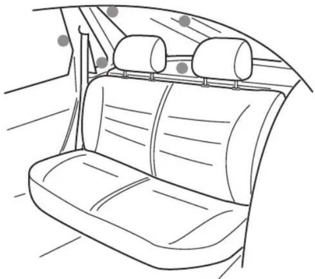
Good positions to the rear are (see fig. 15, page 8):
- On the boot cover
- On the ceiling
- Next to the window
- On the C pillar
▶Pull off the protective foil and stick the display in a suitable position.

Note
The extension cables are marked: L (left) and R (right).
This marking helps you connect them to the control electronics to ensure that the display is correct. These markings can also be found on the control electronics.

The polarity of the socket cannot be reversed: They can be only be plugged into the connection in one way.
▶Insert the display plug into the socket of the corresponding extension cable (see fig. 16 A, page 8).
▶Guide the extension cable to the control electronics and insert the socket of the extension cable into the connection on the control electronics (see fig. 16 B, page 8).


MagicWatch MWE850 Installing MWE850
6.6 Installing the speaker on the boot cover
The piezoelectronic speaker should be glued to or mounted on a suitable place on the boot cover.
Note the following information when selecting the installation location for the piezoelectronic speaker:
- Note the length of the speaker cable. Note that the boot cover swings upwards on vehicles that have a big tailgate.
- The piezoelectronic speaker must not be covered or damaged by any objects placed on the boot cover.
- You can set the volume to either off (Off), low (Lo), or loud (Hi), using the switch on the front of the speaker.
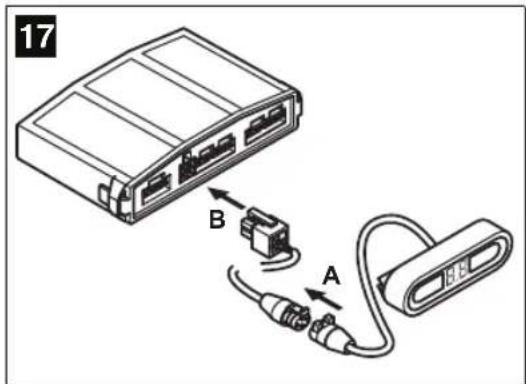
▶Insert the socket of the piezoelectronic speaker into the plug of the extension cable (see fig. 18 A, page 8).
▶Guide the extension cable to the control electronics and insert the socket of the extension cable into the connection on the control electronics (see fig. 18 B, page 8).
▶Remove the protective foil and affix the speaker ...
▶Or attach it using suitable screws.
6.7 Connecting the control electronics

Caution!
Make sure the polarity is correct.

On some vehicles, the reversing light only works when the ignition is switched on. In this case, you must switch on the ignition in order to identify the positive and negative wires.
▶Connect the red cable (fig. 19.2, page 8) on the control electronics to the positive wire (+) of the reversing light (fig. 19.1, page 8).
Connect the black cable (fig. 19.3, page 8) to the earth wire (−) of the reversing light or to earth (bodywork).

Testing functions MagicWatch MWE850
7 T e sting functions
Conduct the functional test as follows:
▶Switch on the ignition and engage reverse gear.
Be very careful when you first operate the device, and make sure you get to know the various sequences of beeps.
| Zone | Description (see fig. 5, page 5) | Sound sequence | LEDs |
| 1 M | WE850 recognises obstacles from a distance of around 1.5 m (measured from the sensor) and signals them with a series of slow beeps from the speaker and by the illumination of the green LED group. | Beep Beep Beep | Green |
| 2 From a distance of around 0.95 m (measured from the sensor) MWE850 switches to the green LED group and to the medium beep sequence. | Beep Beep Beep Beep | Yellow | |
| 3 At | a distance of around 0.3 m (measured from the sensor) and below, MWE850 switches to the red LED group and the the continuous tone. When you reach this zone, stop the vehicle. Otherwise you might damage the vehicle or the obstacle. | Beeeeeep... | Red |

In Zone 3 it can occur that obstacles are not detected, because they are no longer within range of the sensors (depending on design).
The device is equipped with a diagnostic function: If the sensors are defective, you will hear three short beeps when you engage reverse gear.
MagicWatch MWE850 Using MWE850
8 U sing MWE850
MWE850 is activated automatically when you engage reverse gear with the ignition on or the motor running.
As soon as there is an obstacle within the detection range, a repeated signal tone sounds and the green LEDs light up.
As you reverse, the sequence of beeps changes according to the zone you are in, thus indicating the distance (see “Testing functions” chapter on page 44). The display also modifies as the zones change.
Be very careful the first time you use the system, until you are familiar with the various sequences of beeps and the display.

Caution!
Stop the vehicle immediately and check the situation (getting out if necessary), if the following happens while you are reversing:
The device first shows an obstacle while you reverse, and the beeps speed up as normal (i.e. from slow to medium). Suddenly the beeps become slow again or no obstacle at all is shown.
This means that the original obstacle is in the blind spot of the sensors (depending on the design), and you might hit it.

Caution!
If loads or objects on the vehicle (e.g. bicycle racks) protrude over the close area of 0.3 m, there is a danger of accidents. An obstacle can collide with the load or the object before it is detected by the sensors in the close area and MWE850 gives a stop warning (see fig. 11, page 6).
9 Maintaining and cleaning MWE850

Caution!
Do not use sharp or hard objects to clean the device as these may damage the sensors.
▶Clean the sensors with a damp cloth from time to time.
Searching for errors MagicWatch MWE850
10 Searching for errors
The device indicates no function.
The cables to the reversing light are not connected or are switched.
The plug for the display is not connected or is not properly plugged into the control electronics.
The plugs for the sensors are not connected or are not properly plugged into the control electronics.
▶Check the plugs, and plug them in so that they latch in place.
A defective sensor is indicated (three beeps when you engage reverse gear)
If a defective sensor is indicated (see “Testing functions” chapter on page 44), this is what to do:
▶Park the vehicle about a metre away from a large obstacle, such as a garage door.
▶Engage reverse gear.
√The slow beeps sound (Zone 1, see fig. 5, page 5) and the green LEDs of the intact sensors light up.
▶Then stand in front of each sensor in succession.
√ The beeps speed up. The beeps do not change on the defective sensor.
11 Guarantee
Our general guarantee conditions apply. If the product is defective, please send it back to the WAECO branch in your country (addresses on the back of the instruction manual) or to your specialist dealer. For repair and guarantee processing, the following documents must be sent along with the device:
● A copy of the receipt with purchasing date
● A reason for complaint or description of the fault


MagicWatch MWE850 Disposal
12 Disposal
▶ Place the packaging material in the appropriate recycling waste bins wherever possible.

If you wish to finally dispose of the MWE850, ask your local recycling centre or specialist dealer for details about how to do this in accordance with the applicable disposal regulations.
13 Technical data
Detection range: Up to 1.5 m
Ultrasound frequency: 40 kHz
Supply voltage: 11 – 27 Volts DC
Power consumption: 40 mA (standby mode)
250 mA (signal mode)
Operating temperature: -20^ to +70^
Piezoelectronic speaker volume: 100 dB (at 10 cm distance)

The sensors may be painted. WAECO recommends having the sensors painted by a specialist workshop.
Versions, technical modifications and delivery options reserved.
Approval
The device has E13 approval.

natural_image
Pure geometric diagram with crosshair and circular shapes without any text or symbols5 D e scription technique
Description technique MagicWatch MWE850
MagicWatch MWE850 Description technique
natural_image
Pure geometric diagram with crosshair and circular shapes without any text or symbolsMagicWatch MWE850 Installation de MWE850
natural_image
Pure geometric diagram with crosshair and circular shapes (no text or symbols)MagicWatch MWE850 Installation de MWE850
natural_image
Pure geometric diagram with crosshair and circular shapes (no text or symbols)MagicWatch MWE850 Installation de MWE850

Remarque!
natural_image
Pure geometric diagram with crosshair and circular shapes (no text or symbols)natural_image
Pure geometric diagram with crosshair and circular shapes (no text or symbols)MagicWatch MWE850
natural_image
Pure geometric diagram with crosshair and circular shapes without any text or symbolsnatural_image
Pure geometric diagram with crosshair and circular shapes without any text or symbolsnatural_image
Pure geometric diagram with crosshair and circular shapes without any text or symbolsnatural_image
Pure geometric diagram with crosshair and circular shapes (no text or symbols)MagicWatch MWE850 Montaje del MWE850
natural_image
Pure geometric diagram with crosshair and circular shapes without any text or symbolsnatural_image
Three geometric crosshair symbols: a target, a circular pattern, and a vertical line (no text or labels)natural_image
Pure geometric diagram with crosshair and circular shapes without any text or symbolsnatural_image
Pure geometric diagram with crosshair and circular shapes without any text or symbolsnatural_image
Pure geometric diagram with crosshair and circular shapes without any text or symbolsnatural_image
Pure geometric diagram with crosshair and circular shapes (no text or symbols)natural_image
Pure geometric diagram with crosshair and circular shapes without any text or symbolsnatural_image
Pure geometric diagram with crosshair and circular shapes (no text or symbols)natural_image
Pure geometric diagram with crosshair and circular shapes without any text or symbolsnatural_image
Three geometric crosshair symbols: a target, a circular pattern, and a vertical line (no text or labels)
natural_image
Pure geometric diagram with concentric circles and crosshairs, no text or symbols presentnatural_image
Pure geometric diagram with crosshair and circular shapes without any text or symbolsMagicWatch MWE850 MWE850 monteren
6.2 Sensoren monteren

natural_image
Pure geometric diagram with crosshair and circular shapes (no text or symbols)MagicWatch MWE850 MWE850 monteren
natural_image
Pure geometric diagram with crosshair and circular shapes without any text or symbolsnatural_image
Pure geometric diagram with crosshair and circular shapes (no text or symbols)MagicWatch MWE850 Leveringsomfang
natural_image
Pure geometric diagram with crosshair and circular shapes without any text or symbolsMagicWatch MWE850 Montering af MWE850
natural_image
Pure geometric diagram with crosshair and circular shapes (no text or symbols)MagicWatch MWE850 Montering af MWE850
natural_image
Pure geometric diagram with crosshair and circular shapes without any text or symbolsnatural_image
Pure geometric diagram with crosshair and circular shapes (no text or symbols)natural_image
Pure geometric diagram with crosshair and circular shapes (no text or symbols)MagicWatch MWE850 Leveransomfattning
natural_image
Pure geometric diagram with crosshair and circular shapes without any text or symbolsMagicWatch MWE850 Montera MWE850
natural_image
Pure geometric diagram with crosshair and circular shapes (no text or symbols)natural_image
Pure geometric diagram with crosshair and circular shapes (no text or symbols)natural_image
Pure geometric diagram with crosshair and circular shapes (no text or symbols)MagicWatch MWE850 Leveringsomfang
natural_image
Three abstract geometric symbols: crosshair, circular pattern, and perpendicular lines (no text or labels)MagicWatch MWE850 Teknisk beskrivelse

natural_image
Pure geometric diagram with crosshair and circular shapes (no text or symbols)MagicWatch MWE850 Montere MWE850
natural_image
Pure geometric diagram with crosshair and circular shapes (no text or symbols)Deponering MagicWatch MWE850
12 Deponering
natural_image
Pure geometric diagram with crosshair and circular shapes without any text or symbolsMagicWatch MWE850
natural_image
Pure geometric diagram with crosshair and circular shapes without any text or symbolsnatural_image
Pure geometric diagram with crosshair and circular shapes without any text or symbolsnatural_image
Pure geometric diagram with crosshair and circular shapes without any text or symbolsMagicWatch MWE850 MWE850in asentaminen
natural_image
Pure geometric diagram with crosshair and circular shapes (no text or symbols)MagicWatch MWE850 MWE850in asentaminen
natural_image
Pure geometric diagram with crosshair and circular shapes without any text or symbolsMagicWatch MWE850 MWE850in asentaminen
Dorset DT2 8LY - Unit G
Roman Hill Business Park
UK-Broadmayne
+44 1305 854000
+44 1305 854288
Mail: sales@waeco.co.uk
Overseas + Middle East

WAECO Pacific Pty. Ltd.
1 John Duncan Court
Varsity Lakes QLD 4227
+61 7 55076000
昌 +61 7 55076001
Mail: sales@waeco.com.au

WAECO Impex Ltd.
Suites 3210-12 · 32/F · Tower 2
The Gateway · 25 Canton Road
Tsim Sha Tsui · Kowloon
Hong Kong
+852 24632750
吕 +852 24639067
Mail: info@waeco.com.hk

WAECO Impex Ltd.
Taipei Office
2 FL-3 · No. 56 Tunhua South Rd, Sec 2
Taipei 106, Taiwan
+886 2 27014090
+886 2 27060119
Mail: marketing@waeco.com.tw

WAECO Middle East FZCO
R/A 8, SD 6
Jebel Ali, Dubai
+971 4 8833858
+971 4 8833868
Mail: waeco@emirates.net.ae

WAECO USA, Inc.
8 Heritage Park Road
Clinton, CT 06413
+1 860 6644911
+1 860 6644912
Mail: customercare@waecousa.com

www.waeco.com


- MagicWatch MWE850
- F
- MagicWatch MWE850 MWE850 montieren
- Hinweis!
- Contents
- Notes on using the instruction manual
- Caution!
- Note
- Safety and installation instructions
- Safety and installation instructions MagicWatch MWE850
- Warning!
- MagicWatch MWE850 Safety and installation instructions
- Scope of delivery MagicWatch MWE850
- Scope of delivery
- No. in fig. 4, page 4 Quantity Description Item number
- Proper use
- Technical description
- Functional description
- Technical description MagicWatch MWE850
- Detection range
- - Zone 1
- - Zone 2
- - Zone 3
- Example 1 (see fig. 6, page 5)
- Example 2 (see fig. 7, page 5)
- Example 3 (see fig. 8, page 5)
- MagicWatch MWE850 Technical description
- Example 4 (see fig. 9, page 6)
- I n stalling MWE850
- Tools required
- Fitting the sensors
- MagicWatch MWE850 Installing MWE850
- Laying the sensor extension cables
- Fastening the control electronics
- Installing MWE850 MagicWatch MWE850
- Fastening the display
- Installing the speaker on the boot cover
- Connecting the control electronics
- Testing functions MagicWatch MWE850
- T e sting functions
- U sing MWE850
- Maintaining and cleaning MWE850
- Searching for errors
- The device indicates no function.
- A defective sensor is indicated (three beeps when you engage reverse gear)
- Guarantee
- MagicWatch MWE850 Disposal
- Disposal
- Technical data
- Approval
- D e scription technique
- Description technique MagicWatch MWE850
- MagicWatch MWE850 Description technique
- MagicWatch MWE850 Installation de MWE850
- Remarque!
- MagicWatch MWE850 Montaje del MWE850
- MagicWatch MWE850 MWE850 monteren
- Sensoren monteren
- MagicWatch MWE850 Leveringsomfang
- MagicWatch MWE850 Montering af MWE850
- MagicWatch MWE850 Leveransomfattning
- MagicWatch MWE850 Montera MWE850
- MagicWatch MWE850 Teknisk beskrivelse
- MagicWatch MWE850 Montere MWE850
- Deponering
- MagicWatch MWE850 MWE850in asentaminen
- Overseas + Middle East
Brand : WAECO
Model : MagicWatch MWE850
Category : Parking assist