
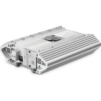
PerfectCharge MCA 1215 - Battery charger DOMETIC - Free user manual and instructions
Find the device manual for free PerfectCharge MCA 1215 DOMETIC in PDF.
| Product type | Battery charger |
| Brand | Dometic |
| Model | PerfectCharge MCA 1215 |
| Input voltage | 90 – 260 V~ |
| Input frequency | 50 Hz – 60 Hz |
| Charge voltage | 14.4 V / 14.7 V |
| Nominal charge current | 15 A |
| Charge current | 0 – 15 A |
| Maintenance voltage | 13.8 V |
| Number of battery outputs | 1 service battery output + 1 starter battery output (ESB) |
| Max. ESB output current | 2 A |
| Compatible battery types | Lead-acid, Gel, AGM |
| Charging mode | 5 levels (modified IU0U) |
| Protections | Short-circuit, overheating, overvoltage, reverse polarity |
| Efficiency at 230 V~ | 87% (typical) |
| Power factor | >97% (full load) |
| Leakage current | <1 mA at 240 V~ |
| Dimensions (Length x Width x Height) | 238 x 179 x 63 mm |
| Weight | 1.6 kg |
| Ambient temperature | -20 °C to +50 °C |
| Storage temperature | -40 °C to +85 °C |
| Cooling | Fan (variable speed) |
| Communications | LIN bus, optional remote control |
| Status display | Multicolor LED |
| Warranty | Legal (depending on country) |
Frequently Asked Questions - PerfectCharge MCA 1215 DOMETIC
User questions about PerfectCharge MCA 1215 DOMETIC
0 question about this device. Answer the ones you know or ask your own.
Ask a new question about this device
Download the instructions for your Battery charger in PDF format for free! Find your manual PerfectCharge MCA 1215 - DOMETIC and take your electronic device back in hand. On this page are published all the documents necessary for the use of your device. PerfectCharge MCA 1215 by DOMETIC.
USER MANUAL PerfectCharge MCA 1215 DOMETIC
natural_image
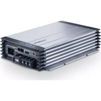
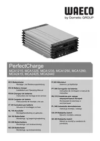
Exterior view of a server rack unit (no visible text or symbols)MCA1215, MCA1225, MCA1235, MCA1250, MCA1280, MCA2415, MCA2425, MCA2440
Battery charger
Installation and Operating Manual.....8
Batterielader
MCA1250/1280/2425/2440
flowchart
graph TD
    A["+"] --> B["LIN"]
    C["-"] --> B
    B --> D["+"]
    E["+"] --> F["-"]
    G["MPC01 MCA-HS1 (IBS)"] --> H["Square symbol"]
    H --> I["Circle symbol"]
    I --> J["Square symbol"]
    J --> K["Circle symbol"]
Please read this instruction manual carefully before installation and first use, and store it in a safe place. If you pass on the product to another person, hand over this instruction manual along with it.
Table of contents
1 Explanation of symbols....9
2 General safety instructions....9
3 Intended use ....14
4 Scope of delivery .....14
5 Accessories....15
6 Technical description ..... 15
7 Installing the device ....18
8 Connecting the device 20
9 Using the device 26
10 Maintaining and cleaning the device. 28
11 Troubleshooting 29
12 Warranty 30
13 Disposal.... 30
14 Technical data....31
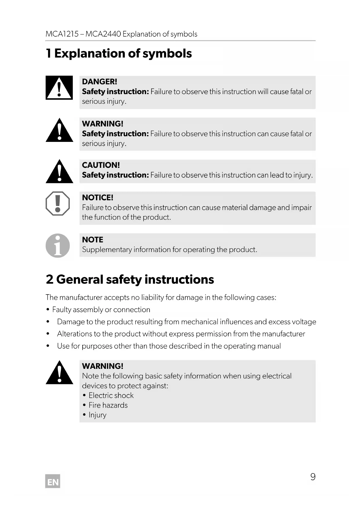
1 Explanation of symbols

DANGER!
Safety instruction: Failure to observe this instruction will cause fatal or serious injury.

WARNING!
Safety instruction: Failure to observe this instruction can cause fatal or serious injury.

CAUTION!
Safety instruction: Failure to observe this instruction can lead to injury.

NOTICE!
Failure to observe this instruction can cause material damage and impair the function of the product.

NOTE
Supplementary information for operating the product.
2 General safety instructions
The manufacturer accepts no liability for damage in the following cases:
- Faulty assembly or connection
- Damage to the product resulting from mechanical influences and excess voltage
• Alterations to the product without express permission from the manufacturer - Use for purposes other than those described in the operating manual

WARNING!
Note the following basic safety information when using electrical devices to protect against:
- Electric shock
- Fire hazards
- Injury
2.1 General safety

DANGER!
- In the event of fire, use a fire extinguisher which is suitable for electrical devices.

WARNING!
- Only use the device as intended.
- Disconnect the device from the mains:
– Before cleaning and maintenance
- After use
- Before changing a fuse
- If you disassemble the device:
- Detach all connections
-
Make sure that no voltage is present at any of the inputs and outputs
-
The device may not be used if the device itself or the connection cable are visibly damaged.
- If this power cable for this device is damaged, it must be replaced by the manufacturer, customer service or a similarly qualified person in order to prevent safety hazards.
- This device may only be repaired by qualified personnel. Inadequate repairs may cause serious hazards.
- This device can be used by children aged 8 years or over, as well as by persons with diminished physical, sensory or mental capacities or a lack of experience and/or knowledge, providing they are supervised or have been taught how to use the device safely and are aware of the resulting risks.
• Electrical devices are not toys.
Always keep and use the appliance out of the reach of children.
- Children must be supervised to ensure that they do not play with the device.

NOTICE!
- Before start-up, check that the voltage specification on the type plate is the same as that of the power supply.
- Ensure that other objects cannot cause a short circuit at the contacts of the device.
- Never pull the plug out of the socket by the connection cable.
- Store the device in a dry and cool place.
2.2 Safety when installing the device

DANGER!
- Never mount the device anywhere where there is a risk of gas or dust explosion.

CAUTION!
- Ensure that the device is standing firmly.
The device must be set up and fastened in such a way that it cannot tip over or fall down.

NOTICE!
- Do not expose the device to a heat source (such as direct sunlight or heating). Avoid additional heating of the device in this way.
- Set up the device in a dry location where it is protected against splashing water.
2.3 Safety when connecting the device electronically

DANGER! Danger of electrocution
- For installation on boats:
If electrical devices are incorrectly installed on boats, corrosion damage might occur. Have the device installed by a specialist (marine) electrician.
- If you are working on electrical systems, ensure that there is somebody close at hand who can help you in emergencies.

WARNING!
- Always use sockets which are grounded and secured by residual current circuit breakers.
• Make sure that the lead has a sufficient cross-section.
- Lay the cables so that they cannot be damaged by the doors or the bonnet.
Crushed cables can lead to serious injury.

CAUTION!
- Lay the cables so that they cannot be tripped over or damaged.

NOTICE!
- Use ductwork or cable ducts if it is necessary to lay cables through metal panels or other panels with sharp edges.
- Do not lay the 230 V mains cable and the 12 V DC cable in the same duct.
- Do not lay the cable so that it is loose or heavily kinked.
- Fasten the cables securely.
- Do not pull on the cables.
2.4 Operating the device safely

DANGER! Danger of electrocution
- Do not touch exposed cables with your bare hands. This applies especially when operating the device from the AC mains.
- To be able to disconnect the device quickly from the mains, the socket must be close to the device and be easily accessible.

WARNING!
- Only use the device in closed, well-ventilated rooms.
- Do not operate the device in systems with lead acid batteries. These batteries give off explosive hydrogen gas that can be ignited by sparks on electrical connections.

CAUTION!
- Do not operate the device
– In salty, wet or damp environments
– In the vicinity of corrosive fumes
– In the vicinity of combustible materials
– In areas where there is a danger of explosions.
- Before starting the device, ensure that the power supply line and the plug are dry.
• Always disconnect the power supply when working on the device.
- Please observe that parts of the device may still conduct voltage even if the fuse has blown.
- Do not disconnect any cables when the device is still in use.

NOTICE!
- Make sure the air inlets and outlets of the device are not covered.
- Ensure good ventilation.
2.5 Safety precautions when handling batteries

WARNING!
- Batteries contain aggressive and caustic acids. Avoid battery fluid coming into contact with your body. If your skin does come into contact with battery fluid, wash the part of your body in question thoroughly with water. If you sustain any injuries from acids, contact a doctor immediately.

CAUTION!
- When working on the batteries, do not wear any metal objects such as watches or rings. Lead acid batteries can cause short circuits which can cause serious injuries.
• Danger of explosions!
Never attempt to charge a frozen or defective battery.
Place the battery in a frost-free area and wait until the battery has acclimatised to the ambient temperature. Then start the charging process.
- Wear goggles and protective clothing when you work on batteries. Do not touch your eyes when you are working on the battery.
- Do not smoke and ensure that no sparks can arise in the vicinity of the engine or battery.

NOTICE!
- Only use rechargeable batteries.
- Prevent any metal parts from falling on the battery. This can cause sparks or short-circuit the battery and other electrical parts.
- Make sure the polarity is correct when connecting the battery.
- Follow the instructions of the battery manufacturer and those of the manufacturer of the system or vehicle in which the battery is used.
- If you need to remove the battery, first disconnect the earth connection. Disconnect all connections and all consumers from the battery before removing it.
3 Intended use
The PerfectCharge MCA360 battery charger can charge or supply a retention voltage to batteries which are used to generate power in vehicles or on boats.
The MCA charger can be used to continuously charge supply or starter batteries.
This allows the batteries to be charged and to maintain a high charge level:
- 12 V batteries: MCA1215, MCA1225, MCA1235, MCA1250, MCA1280
• 24 V batteries: MCA2415, MCA2425, MCA2440
The MCA battery charger are designed to charge the following battery types:
- Lead starter batteries
- Lead gel batteries
• Absorbed glass mat (AGM) batteries
Never use the devices to charge other battery types (such as NiCd or NiMH).

WARNING! Danger of explosions
- Do not charge batteries with a cell short circuit. The oxyhydrogen they produce can cause explosions.
- Do not charge lead batteries in unventilated rooms. The oxy-hydrogen they produce can cause explosions.
- Do not charge nickel cadmium and non-rechargeable batteries with the charger. The cases of these batteries can burst explosively.
4 S c o p e o f d
Quantity Description
1 Battery charger
2 230 V power cable
3 Installation and operating manual
Check before starting up the device that all parts are available belonging to the scope of delivery.
5 A c c e s s o r i
Available as accessory (not included in scope of delivery):
Description Reference no.
Remote Control MCA-RC1 9600000100
Temperature sensor MCA-TS1 9600000099
Battery sensor MCA-HS1 (IBS) 9600000101
Battery Management System PerfectControl MPC01 9600000122
6 Technical description
The low weight and compact construction of the battery charger allow for easy installation in mobile homes, commercial vehicles or motor and sailing yachts. It charges batteries that are used on board vehicles or boats to generate power or supplies them with a retention voltage so that they do not discharge.
A control lamp on the device enables constant monitoring in the battery charger.
The device has the following protective systems:
- Short circuit
• Overheating protection
• with sensor (accessory): Battery overheating
The device can also be integrated into a LIN bus using two connections.
The cooling system uses fans whose speed depends on the charging power and can be switched off using an external switch.
6.1 Device versions
The PerfectCharge MCA battery chargers are available in different versions.
Your MAC battery charger can be used to charge batteries up to a specified battery capacity (see chapter "Technical data" on page 31):
- MCA1215: suitable for charging one supply battery and one starter battery
- MCA1225, MCA1235: suitable for charging up to two supply batteries and one starter battery
• MCA1250, MCA1280: suitable for charging up to three supply batteries
• MCA2415: suitable for charging up to two supply batteries
• MCA2425, MCA2440: suitable for charging up to three supply batteries
For the identification of your device, see the reference number on the type plate.
6.2 Connections and controls

NOTE
The version for continental Europe is depicted.
No. in fig. 1, page 3 Explanation/function
| 1 Mains connection | ||||||
| 2 LIN2 bus connection | ||||||
| 3 TENMP/LIN1 bus connection | ||||||
| 4 CN2 socket for Alarm and Fan | ||||||
| 5 Status LED | ||||||
| 6 | D | I | P | s | w | i |
| 7 Battery terminals (+) | ||||||
| 8 Battery terminals (-) | ||||||
| 9 Starter battery connection(MCA1215, MCA1225, MCA1235 only) | ||||||
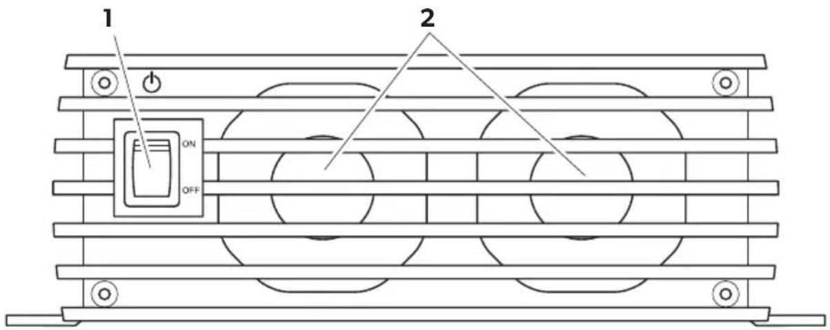
No. in fig. 2, page 4 Explanation/function
1 On/Off switch
2 Fan
6.3 Battery charging function
The charging characteristics are referred to as modified IUOU characteristics.
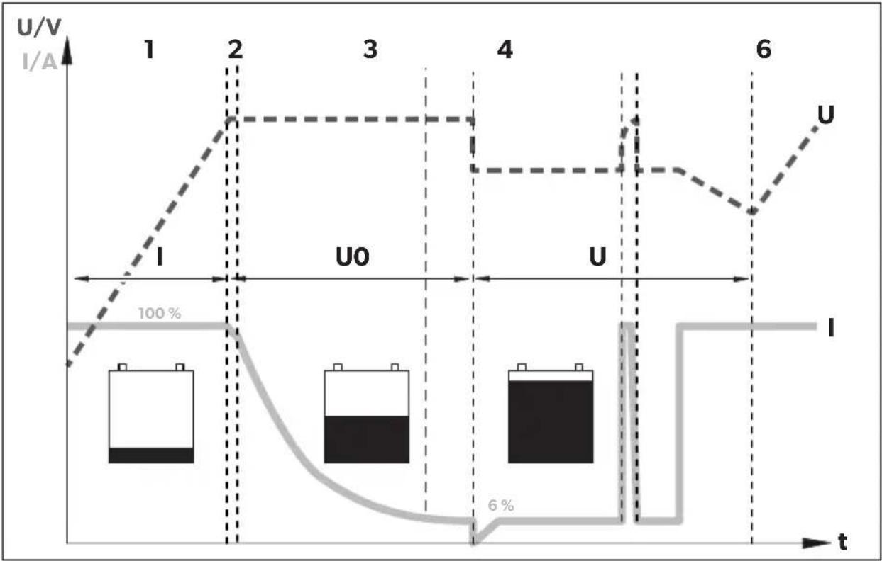
line
| t | I/A (Solid Line) | U/V (Dashed Line) | |---|------------------|-------------------| | 1 | ~100% | ~100% | | 2 | ~100% | ~100% | | 3 | ~100% | ~100% | | 4 | ~100% | ~100% | | 5 | ~100% | ~100% | | 6 | ~100% | ~100% |1: I phase (bulk)
At the beginning of the charging process, the flat battery is charged with a constant current (100 % charge current) until the battery voltage reaches the charging voltage. The charging current decreases when the battery has reached this charging level.
2, 3, 4: U0 phase (absorption)
Now the three-stage absorption charging process (U0 phase) begins, where the duration depends on the battery. The voltage remains constant (U0). In the first 2 minutes, the charging of the battery is determined. Then the main charging phase begins when the battery is fully charged.
Once the battery is completely charged, or the charging current is below 6% of the rated charging current for 15 minutes, the U0 phase has finished.
5: U phase (float)
After the U0 phase, the battery charger switches to conservation charging function (U phase).
If DC loads are connected, they are powered by the device. Only if the power required exceeds the capacity of the device is this surplus power provided by the battery. The battery is then discharged until the device re-enters the I phase and charges the battery.
6: 12-day conditioning
Every 12 days, the battery charger switches back to phase 1 for 85 min in order to revive the battery. This prevents any fatigue symptoms such as sulphation.
7 Installing the device
When selecting the installation location, observe the following instructions:
- The device can be installed horizontally or vertically.
- Do not install the device
– In wet or damp environments
– In dusty environments
– In the vicinity of combustible materials
– In areas where there is a danger of explosions.
- The place of installation must be well ventilated. A ventilation system must be available for installations in small, enclosed spaces. The clearance around the device must be at least 25 cm.
- The air inlet on the underside and the air outlet on the back of the device must remain clear.
-
For ambient temperatures higher than 40\ °C (such as in engine or heating compartments, or direct sunlight), the heat from the device under load can lead to reduced output.
-
The device must be installed on a level and sufficiently sturdy surface.
- Do not install the device in the same area as the batteries.
- Do not install the device above batteries, because they can emit corrosive sulphur fumes that will damage the device.

NOTICE!
Before drilling any holes, make sure that no electrical cables or other parts of the vehicle can be damaged by drilling, sawing and filing.
For installation and mounting you will need the following tools:
- Pen for marking
- Drill bit set
- Drill
- Screwdriver
To secure the device in place you will need:
• Machine bolts (M4) with washers and self-locking nuts or
- self-tapping screws or wood screws.
Fasten the device as follows:
▶ Hold the device against the installation location.
▶ Mark the fastening points.
▶ Fasten the device with one screw through each hole in the holders.
8 Connecting the device
8.1 Connecting to battery and power supply
Connecting the battery
Observe the following instructions when connecting the battery:

CAUTION!
- Avoid coming into contact with the battery fluid.
-
Batteries with a cell short circuit may not be charged, as explosive gases may form due to overheating of the battery.
-
Make sure the battery terminals are clean when connecting them.
- Make sure the plug connector is fitted securely.
- Select a connection cable with a sufficient cross-section (see chapter "Technical data" on page 31).
- Lay the cables in accordance with VDE°100 (Germany).
- Connect the negative cable directly to the negative terminal of the battery, and not to the chassis of a vehicle or boat.
- Use the following cable colours:
- Red: positive connection
- Black: negative connection
- Do not reverse the polarity. Reversing the polarity can cause damage to the device.
▶ Lay the positive cable from the battery charger to the positive terminal of the battery and connect it.
▶ Lay the negative cable from the battery charger to the negative terminal of the battery and connect it.
Connecting the 230 V power supply
Plug the 230 V connection cable included in the delivery into the MCA battery charger's "AC INPUT" socket.
▶ Connect the device with the he 230 V connection cable to a 230 V socket which is protected by a residual current circuit breaker.
8.2 Charge versions
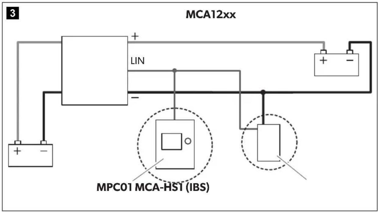
| fig. 3, page 5 | |
| Battery sensorMCA-HS1 (IBS)(12 V only) | Perfect ControlMPC01(12 V only) |
| - | - |
| √ - √ - | |
| √ | √ |
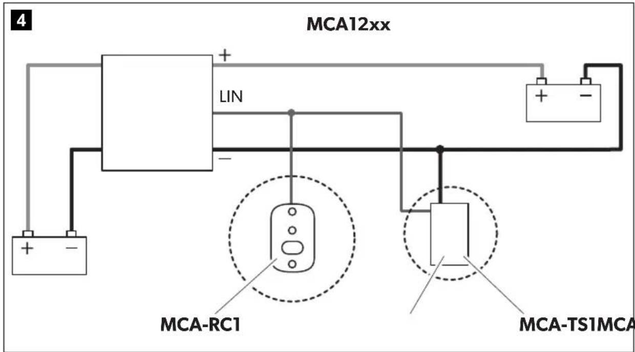
| fig. 4, page 5 | |
| Remote controlMCA-RC1 | Temperature sensorMCA-TS1 orBattery sensorMCA-HS1 (IBS)(12 V only) |
| - | |
| -√ | |
| √ | √ |
- without; √ with
Charging the battery
▶ Connect the battery to the "DC OUTPUT" socket of the MCA battery charger.
- Make sure the polarity of the connections is correct.
Charging the starter battery (MCA1215, 1225, 1235 only)
▶ Connect the starter battery to the "ESB" socket of the MCA battery charger.
- Make sure the polarity of the connections is correct.
Charging using the temperature sensor MCA-TS1 (accessory)
▶ Connect the temperature sensor to the TEMP/LIN connection.
√ The charging voltage is adjusted according to the temperature measured.
Charging using the IBS battery sensor MCA-HS1 (accessory) (12 V only)
▶ Connect the battery sensor to the TEMP/LIN connection.
√ The battery sensor transmits the battery temperature and the battery voltage to the charger via the LIN communication port. The charging voltage is regulated according to the temperature. Any potential loss of voltage in the connecting cables is also compensated.
Charging using the battery management system PerfectControl MPC01 (accessory) (12 V only)
▶ Set the DIP switches 1 to 3 on the MCA battery charger to "ON" (chapter "Setting the DIP switches" on page 24).
You can find detailed information in the operating manual for MPC01.
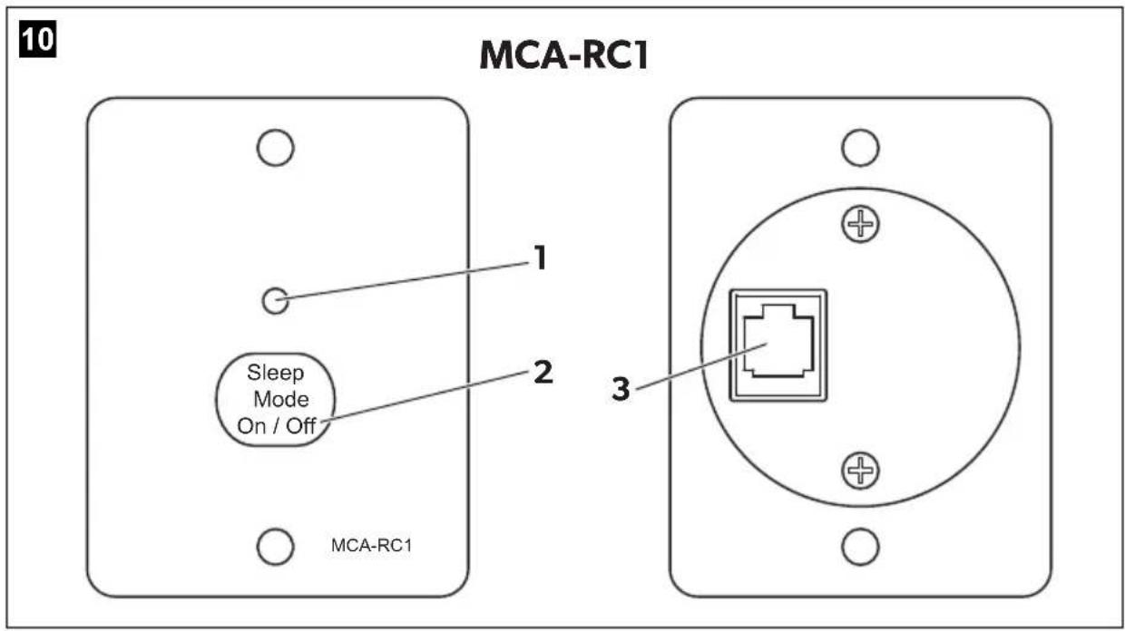
Charging using the remote control MCA-RC1 (accessory)

NOTE
The length of the RJ-11 cable may not exceed 7 m.
▶ Insert one end of the RJ-11 cable into the socket (fig. 10 3, page 7) of the MCA-RC1.
▶ Insert the other end of the RJ-11 cable into the TEMP/LIN1 socket on the MCA battery charger.
8.3 Wiring diagrams
Example of a wiring diagram, 12 V: see fig. 5, page 6.
No. in fig. 5, page 6 Explanation/function
| 1 MCA charger | ||||||
| 2 | C | o | n | s | u | m |
| 3 PerfectControl MPC01 | ||||||
| 4 12 V battery sensor IBS | ||||||
| 5 12 V battery | ||||||
| 6 | F | u | s | e | ||
| 7 Starter battery | ||||||
Example of a wiring diagram, 24 V: see fig. 6, page 6.
No. in fig. 6, page 6 Explanation/function
| No. in fig. 6, page 6 | Explanation/function |
| 1 MCA charger | |
| 2 12 V battery | |
| 3 Starter battery | |
8.4 Pin assignment
The pins for the TEMP/LIN1 bus socket are assigned as follows:
| Pin in fig. 7, page 6 | Allocation | |||
| 1 R_VCC | ||||
| 2 | GND | |||
| 3 | T | E | M | P |
| 4 | B | A | T | - |
| 5 LIN BUS DATA I/O | ||||
| 6 | B | A | T | + |
The pins for the LIN2 bus socket are assigned as follows:
| Pin in fig. 7, page 6 | Allocation | |||
| 1 R_VCC | ||||
| 2 | B | A | T | - |
| 3 | NC | |||
| 4 | B | A | T | - |
| 5 LIN BUS DATA I/O | ||||
| 6 | B | A | T | + |
The pins for the CN2 socket (alarm signal and fan control) are assigned as follows:
| Pin in fig. 8, page 6 | Allocation |
| 1 NC (Normally Closed): normally closed contact | |
| 2 NO (Normally Open): normally open contact | |
| 3 COM (Common): common contact | |
| 4 Sleep mode control | |
| 5 | GND |
| 4 – 5 bridged Sleep mode on | |
| 4 – 5 open Sleep mode off | |
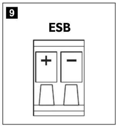
The pins for the ESB socket (starter battery connection) are assigned as follows:
| Pin in fig. 9, page 6 | Allocation |
| + | VCC |
| - | GND |
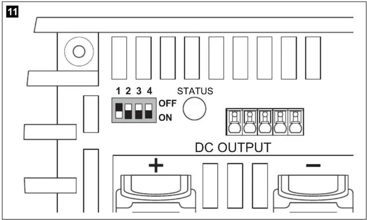
8.5 Setting the DIP switches
You can adjust the device using the DIP switch.
S1 is used to set the voltage at which the device switches over from the I phase (bulk) to the U0 phase (absorption) (also see chapter "Battery charging function" on page 17). S3 must be set to "OFF".
S2 is used to set the retention voltage. S3 must be set to "OFF".
When a battery sensor is connected, the output voltages is adapted to the temperature for these two functions:
- MCA 12xx: -20mV / ircC
- MCA 24xx: -40mV / ircC
S3 activates the power mode when either S1 or S2, or both, are set to "Off". In power mode, the short circuit, overvoltage and overheating protection are controlled by the internal sensor.
When S1, S2 and S3 are set to "On", then the function control by external devices is activated. Among others the type of battery and the charging voltage are set using the external device in this mode.
S4 regulates the fan function. When S4 is set to "On", then the fan is switched to sleep mode (noise-reduced mode). When S4 is set to "Off", then the fan is not regulated.
▶ Use the DIP switches (fig. 11 page 7) to set the required functions and values: – To set the switchover voltage:
Switch 1 Switch 3 Switchover voltage
| ON OFF 14.4 V / 28.8 V |
| OFF | OFF | 14.7 V / 29.4 V |
- To set the retention voltage:
Switch 2 Switch 3 Retention voltage
| ON OFF 13.5 V / 27.0 V |
| OFF OFF | 13.8 V / 27.6 V |
- To set the power mode:
| Switch 1 | Switch 2 | Switch 3 | Constant voltage | |
| MCA12.. | MCA24.. | |||
| OFF | OFF | ON | 13.2 V | 26.4 V |
| OFF | ON | ON | 13.8 V | 27.6 V |
| ON | OFF | ON | 14.4 V | 28.8 V |
- Enabling the control for external devices (such as MPC01, does not apply to MCA-RC1):
| Switch 1 | Switch 2 | Switch 3 |
| ON | ON | ON |
- To activate sleep mode:
Switch 4
| ON |
9 Using the device
▶ Set the On/off switch to "On".
To switch off the device set the On/off switch to "On".
√ Depending on the charging condition of the battery, the battery charger starts charging or supplies a retention voltage.
√ The "Status" LED (fig. 1 5, page 3) displays the operating status (see following table and chapter "Battery charging function" on page 17).
Display Meaning
| Orange, quickly flashing Phase 1 |
| Orange, slowly flashing Phase 2 |
| Orange, constantly lit Phase 3 |
| Green, constantly lit Phase 4 |
| Green, slowly flashing Phase 5 |
| Red, constantly lit Short circuit or defective fuse |
| Red, quickly flashing Battery or battery charger is overheating |
| Red, slowly flashing Battery undervoltage or overload |
| Red, double flash |
| Fan fault |
| Red, slow double flash |
| Fault at the starter battery connection |

NOTE
In the event of a fault (the Status LED is red), refer to chapter "Troubleshooting" on page 29.
When you have connected the remote control MCA-RC1 (accessory)
▶ Activate or deactivate sleep mode (noise reduced mode) using the "Sleep Mode" button (fig. 10 2, page 7).
The fan is not regulated in sleep mode.
√ The LED (fig. 10 1, page 7) on the MCA-RC1 indicates the operating status (see following table).
Mode Display Meaning
| Sleep mode activated Orange, constantly lit Phase 1 to 5 | ||
| Sleep mode deactivated | Green, slowly flashing | Phase 1 to 4 |
| Green, constantly lit Phase 5 | ||
| Fault Red, constantly lit Short circuit or defective fuse | ||
| Red, quickly flashing Battery or battery charger is overheating | ||
| Red, slowly flashing Battery undervoltage or overload | ||
| Red, double flash Fan fault | ||
| Red, slow double flash | Fault at the starter battery connection | |

NOTE
In the event of a fault (the Status LED is red), refer to chapter "Troubleshooting" on page 29.
10 Maintaining and cleaning the device

NOTICE!
Do not use any sharp or hard objects for cleaning since they may damage the device.
▶ Disconnect the device from the 230 V power supply.
▶ Disconnect the device from the battery.
▶ Prevent the device from being switched on.
▶ Occasionally clean the device with a damp cloth.
▶ Regularly clean the vents.
▶ Check the electrical wiring at least once a year.
Repair any defects such as loose connections or burnt cables.
11 Troubleshooting
The "Status" LED (fig. 1 5, page 3) displays the fault:
| LED display Cause Remedy | ||
| Red, slowly flashing Battery undervoltage or battery overload | Check the battery.Switch the battery charger off and on again. | |
| Defective battery Replace the battery. | ||
| Red, slowly flashing Overheating Improve the ventilation of the battery charger or battery.Make sure that no ventilation openings are covered.If necessary, reduce the ambient temperature. | ||
| Red, permanently lit Short circuit or reversed polarity | Connect the battery charger with the correct polarity.Rectify the short circuit.Check if the fuse has triggered and replace it if necessary. | |
| Red, double flash Fan fault Check the fan for dirt or damage. | ||
| Red, slow double flash | Fault at the starter battery connection | Check the starter battery connection for a short circuit. |

NOTE
If you have detailed questions on the battery specifications, please contact the battery manufacturer.
12 Warranty
The statutory warranty period applies. If the product is defective, please contact the manufacturer's branch in your country (see the back of the instruction manual for the addresses) or your retailer.
For repair and guarantee processing, please include the following documents when you send in the device:
• A copy of the receipt with purchasing date
- A reason for the claim or description of the fault
13 Disposal
▶ Place the packaging material in the appropriate recycling waste bins wherever possible.
If you wish to finally dispose of the product, ask your local recycling centre or specialist dealer for details about how to do this in accordance with the applicable disposal regulations.
14 Technical data
General technical data
| MCA12xx, MCA24xx | |
| Battery types: Lead-acid, gel, AGM, Li-Ion | |
| Heat dissipation: Fan | |
| Charge mode: 5-level | |
| Maximum ambient temperature: -20 °C - +50 °C | |
| Storage temperature: -40 °C - +85 °C | |
| Air humidity: 20 - 90 % | |
| Temperature coefficient: ± 0.03% / °C (0 - 50 °C) | |
| Temperature compensation (MCA12xx)Temperature compensation (MCA24xx): | -20 mV/°C (battery sensor)-40 mV/°C (battery sensor) |
| Vibration: | 10 - 500 Hz2 g for 10 min/cycle within 60 minutes for X, Y and Z axis |
| Voltage insulation: I/P - O/P: 4 kV~ | I/P - FG: 1.7 kV~O/P - FG: 0.7 kV~ |
| Insulation resistance: | I/P - O/P: 100 MΩ/500 V--- |
| Alarm signal: | via relay contact |
| Communication: | via LIN-BUS |
| Sleep mode (noise-reduced mode): | via remote control (accessory) or DIP switch |
| Remote control (accessory): | On/off switch, three-colour LED, sleep mode option |
| Testing/certification: | CE |
Protective devices
| MCA12xx, MCA24xx | |
| Output side short circuit: Current is reduced to 25 % of the maximum current | |
| Overvoltage: 16 V | |
| Battery charger over temperature: | 100 °C ± 5 °C (measured internally) |
| Battery over temperature: | 52 °C ± 5 °C (with battery sensor) |
Input data
| MCA1215 | MCA1225 MCA1235 MCA1250 MCA1280 | ||||
| Rated input voltage: 90 – 260 V~ | |||||
| Output factor correction: >97% (full load) | |||||
| Input frequency: 50 Hz – 60 Hz | |||||
| Efficiency at 230 V~ : | 8 | ||||
| Leakage current: | <1 mA at 240 V~ | ||||
| Input current at 100 V~ : | 2.5 A | 4.1 A | 6.2 A | 8.24 A | 13.3 A |
| Input current at 240 V~ : | 1.07 A | 1.8 A | 2.8 A | 3.6 A | 5.4 A |
| MCA2415 | MCA2425 | MCA2440 | |
| Rated input voltage: | 90 – 260 V~ | ||
| Output factor correction: | >97% (full load) | ||
| Input frequency: | 50 Hz – 60 Hz | ||
| Efficiency at 230 V~ : | 90 % | ||
| Leakage current: | <1 mA at 240 V~ | ||
| Input current at 100 V~ : | 4.2 A | 8.3 A | 13.3 A |
| Input current at 240 V~ : | 1.7 A | 3.6 A | 5.4 A |
Output data
| MCA1215 | MCA1225 MCA1235 MCA1250 MCA1280 | ||||
| Charging voltage: 14.4 V / 14.7 V | |||||
| Retention voltage: 13.8 V | |||||
| Rated charging current: | 15 A | 25 A | 35 A | 50 A | 80 A |
| Charging current: 0 – 15 A 0 – 25 A 0 – 35 A 0 – 50 A 0 – 80 A | |||||
| O u t | p | u | t | s | : |
| ESB outputs (Starter battery): | 1 | 1 | 1 | - | - |
| ESB charging voltage : | 13.8 V | 13.8 V | 13.8 V | - | - |
| ESB charging current: | 2 A | 2 A | 2 A | - | - |
| MCA2415 | MCA2425 | MCA2440 | |
| Charging voltage: | 28.8 V / 29.4 V | ||
| Retention voltage: | 27.6 V | ||
| Rated charging current: | 12.5 A | 25 A | 40 A |
| Charging current: | 0 – 12.5 A | 0 – 25 A 0 | -40 A |
| O u t | p | u | t |
S :
Dimensions and weight:
| MCA1215 MCA1225 MCA1235 | |||
| Dimensions L x W x H (mm): 238 x | 179 x 63 | 238 x 179 x 63 | 274 x 179 x 63 |
| Weight: 1.6 kg 1.7 kg 1.9 kg | |||
| MCA1250 MCA1280 | ||
| Dimensions L x W x H (mm): 283 x | 208.5 x 75 303x208.5x75 | |
| Weight: 3.1 kg 3.9 kg | ||
| MCA2415 | MCA2425 | MCA2440 | |
| Dimensions L x W x H (mm): 238 x 179 x 63 | 283 x 208.5 x 75 | 303x208.5 x75 | |
| Weight: | 1.6 kg | 2.9 kg | 3.9 kg |
Technical data MCA-RC1 (accessory)
| MCA-RC1 | |
| Rated input voltage: | 10.5 – 15 V= |
| Standby current consumption: | < 40 mA |
| Maximum ambient temperature: | -10 °C – +45 °C |
| Storage temperature: | -30 °C – +70 °C |
line
| t | U/A (dashed line) | I/A (solid line) | |---|-------------------|------------------| | 1 | High | Low | | 2 | Medium | Low | | 3 | Medium | Low | | 4 | Medium | Low | | 5 | Medium | Low | | 6 | Low | Low |1: I-Phase (Bulk)
| ON OFF 13,5 V / 27,0 V |
| OFF OFF | 13,8 V / 27,6 V |
- Batteries 12 V : MCA1215, MCA1225, MCA1235, MCA1250, MCA1280
- Batteries 24 V : MCA2415, MCA2425, MCA2440
6 Description technique
line
| t | U/A (dashed line) | I (solid line) | |---|---|---| | 1 | High | Low | | 2 | High | Low | | 3 | High | Low | | 4 | High | Low | | 5 | Medium | Low | | 6 | Low | Low |1: Phase I (Bulk)
Signal Signification
Mode Signal Signification
2, 3, 4: Fase U0 (Absorption)
| ON OFF 13,5 V / 27,0 V |
| OFF OFF | 13,8 V / 27,6 V |
- Ajustar el Power Mode:
| Interruptor 1 | Interruptor 2 | Interruptor 3 | Tensión constante | |
| MCA12.. | MCA24.. | |||
| OFF | OFF | ON | 13,2 V | 26,4 V |
| OFF | ON | ON | 13,8 V | 27,6 V |
| ON | OFF | ON | 14,4 V | 28,8 V |
| Interruptor 1 | Interruptor 2 | Interruptor 3 |
| ON | ON | ON |
2, 3, 4: Fase U0 (Absorption)
- Batterie da 12 V: MCA1215, MCA1225, MCA1235, MCA1250, MCA1280
- Batterie da 24 V: MCA2415, MCA2425, MCA2440
• 12-V-accu's: MCA1215, MCA1225, MCA1235, MCA1250, MCA1280
• 24-V-accu's: MCA2415, MCA2425, MCA2440
WAARSCHUWING! Explosiegevaar!
Accusensor MCA-HS1 (IBS) 9600000101
Accumanagementsysteem PerfectControl MPC01 9600000122
line
| t | U/A (dashed line) | I/A (solid line) | |---|---|---| | 1 | High | Low | | 2 | High | Low | | 3 | High | Low | | 4 | High | Low | | 5 | Medium | Low | | 6 | Low | Low |1: I-fase (Bulk)
6: 12-daagse conditionering
| ON OFF 13,5 V / 27,0 V |
| OFF | OFF | 13,8 V / 27,6 V |
- Power Mode instellen:
| Schakelaar 1 | Schakelaar 2 | Schakelaar 3 | Gestabiliseerde spanning | |
| MCA12.. | MCA24.. | |||
| OFF | OFF | ON | 13,2 V | 26,4 V |
| OFF | ON | ON | 13,8 V | 27,6 V |
| ON | OFF | ON | 14,4 V | 28,8 V |
6.1 Apparatvarianter
PerfectCharge MCA-batteriopladerne leveres i forskellige apparatvarianter.
MCA-batteriopladeren kan oplade batterier indtil en fastlagt batterikapacitet (se kapitlet „Tekniske data“ på side 233):
line
| t | U/V (I/A) | |---|---| | 1 | 0 | | 2 | High | | 3 | High | | 4 | Low | | 5 | Low | | 6 | High |1: I-fase (Bulk)
2, 3, 4: U0-fase (Absorption)
| ON OFF 13,5 V / 27,0 V |
| OFF OFF | 13,8 V / 27,6 V |
- Indstilling af power mode:
| Kontakt 1 | Kontakt 2 | Kontakt 3 | Konstant spænding | |
| MCA12.. | MCA24.. | |||
| OFF | OFF | ON | 13,2 V | 26,4 V |
| OFF | ON | ON | 13,8 V | 27,6 V |
| ON | OFF | ON | 14,4 V | 28,8 V |
line
| t | U/V (I/A) | U/V (U/V) | |---|---|---| | 1 | Low | High | | 2 | High | High | | 3 | High | High | | 4 | Low | High | | 5 | High | Medium | | 6 | Low | Low |1: I-fas (bulk)
2, 3, 4: U0-fas (absorption)
6: 12-dagars konditionering
line
| t | U/V (I/A) | |---|---| | 1 | 0 | | 2 | High | | 3 | High | | 4 | Low | | 5 | Low | | 6 | High |1: I-fase (Bulk)
I starten av ladingen lades det tomme batteriet med konstant strøm (100 % ladestrøm) til batterispenningen när ladespenningen. Hvis batteriet när dette spenningsnivået, avtar ladestrømmen.
- Penn for marking
- Borsett
- Bormaskin
- Skrutrekker
8.5 Stille inn DIP-bryter
Du kan tilpasse apparatet med DIP-bryteren.
| ON OFF 13,5 V / 27,0 V |
| OFF | OFF | 13,8 V / 27,6 V |
- Stille inn Power Mode:
| Bryter 1 | Bryter 2 | Bryter 3 | Konstant spenning | |
| MCA12.. | MCA24.. | |||
| OFF | OFF | ON | 13,2 V | 26,4 V |
| OFF | ON | ON | 13,8 V | 27,6 V |
| ON | OFF | ON | 14,4 V | 28,8 V |
| Bryter 1 | Bryter 2 | Bryter 3 |
| ON | ON | ON |
2, 3, 4: U0-фаза (Absorption)
- Akumulatory 12 V: MCA1215, MCA1225, MCA1235, MCA1250, MCA1280
- Akumulatory 24 V: MCA2415, MCA2425, MCA2440
2, 3, 4: Faza U0 (Absorption)
| ON OFF 13,5 V / 27,0 V |
| OFF | OFF | 13,8 V / 27,6 V |
line
| t | U/V (I/A) | |---|---| | 1 | 0 | | 2 | High | | 3 | High | | 4 | Low | | 5 | Low | | 6 | High |1: I fáza (celok)
| ON OFF 13,5 V / 27,0 V |
| OFF | OFF | 13,8 V / 27,6 V |
– Nastavenie Power Mode:
| Spínač 1 | Spínač 2 | Spínač 3 | Konštantné napätie | |
| MCA12.. | MCA24.. | |||
| OFF | OFF | ON | 13,2 V | 26,4 V |
| OFF | ON | ON | 13,8 V | 27,6 V |
| ON | OFF | ON | 14,4 V | 28,8 V |
- Uvol'nenie riadenia pre externé zariadenia (napr. MPC01, neplatí pre MCA-RC1):
| Spínač 1 | Spínač 2 | Spínač 3 |
| ON | ON | ON |
- Baterie 12 V: MCA1215, MCA1225, MCA1235, MCA1250, MCA1280
• Baterie 24 V: MCA2415, MCA2425, MCA2440
line
| t | U/V (I/A) | |---|---| | 1 | 0 | | 2 | High (U/V) | | 3 | High (U/V) | | 4 | Low (U/V) | | 5 | High (U/V) | | 6 | Low (U/V) |1: Fáze I (Bulk)
| ON (ZAP) OFF (VYP) 13,5 V / 27,0 V |
| OFF (VYP) OFF (VYP) 13,8 V / 27,6 V |
Dometic Australia Pty. Ltd.
1 John Duncan Court
Varsity Lakes QLD 4227
1800212121
+61755076001
Mail: sales@dometic.com.au
AUSTRIA
Dometic Austria GmbH
Neudorferstraße 108
A-2353 Guntramsdorf
+43 2236 908070
品 +43 2236 90807060
Mail: info@dometic.at
BENELUX
Dometic Branch Office Belgium
Zinccstraat 3
B-1500 Halle
+32 2 3598040
+32 2 3598050
Mail: info@dometic.be
BRAZIL
Dometic DO Brasil LTDA
Avenida Paulista 1754, conj. 111
SP 01310-920 Sao Paulo
+551132513352
+551132513362
Dometic Group Asia Pacific
Suites 2207-11 · 22/F · Tower 1
The Gateway · 25 Canton Road,
Tsim Sha Tsui - Kowloon
+85224611386
品 +85224665553
Mail: info@waeco.com.hk
HUNGARY
Dometic Zrt. Sales Office
Kerékgyártó u. 5.
H-1147 Budapest
+3614684400
+3614684401
Dometic Italy S.r.l.
Via Virgilio, 3
1-47122 Forl (FC)
+390543754901
+390543754983
Mail: vendite@dometic.it
JAPAN
Dometic KK
Maekawa-Shibaura, Bldg. 2
2-13-9 Shibaura Minato-ku
Tokyo 108-0023
+81354453333
+81354453339
Mail: info@dometic.jp
MEXICO
Circuito Médicos No. 6 Local 1
Colonia Ciudad Satélite
CP 53100 Naucalpan de Juárez
Estado de México
+52 55 5374 4108
+52 55 5393 4683
Mail: info@dometic.com.mx
NETHERLANDS
Dometic Benelux B.V.
Ecustraat 3
NL-4879 NP Etten-Leur
+31765029000
+31765029019
Mail: info@dometic.nl
NEW ZEALAND
Dometic New Zealand Ltd.
PO Box 12011
Penrose
Auckland 1642
+6496221490
+6496221573
Mail: customerservices@dometic.co.nz
NORWAY
Dometic Norway AS
∅sterøyveien 46
N-3232 Sandefjord
+47 33428450
+47 33428459
Mail: firmapost@dometic.no
POLAND
Dometic Poland Sp. z o.o.
Ul. Puławska 435A
PL-02-801 Warszawa
+48 22 414 3200
+48 22 414 3201
Mail: info@dometic.pl
PORTUGAL
Dometic Spain, S.L.
Komsomolskaya square 6-1
RU-107140 Moscow
+7 495 780 79 39
+7 495 916 56 53
Mail: info@dometic.ru
SINGAPORE
Dometic Pte Ltd
18 Boon Lay Way 06-140 Trade Hub 21
Singapore 609966
+65 6795 3177
三 +65 6862 6620
Mail: dometic@dometic.com.sg
SLOVAKIA
Dometic Slovakia s.r.o. Sales Office Bratislava
Nádražná 34/A
900 28 Ivánka pri Dunaji
+421245529680
Mail: bratislava@dometic.com
SOUTH AFRICA
Dometic (Pty) Ltd.
Regional Office
South Africa & Sub-Saharan Africa
2 Avalon Road
West Lake View Ext 11
Modderfontein 1645
Johannesburg
+27114504978
+27114504976
Mail: info@dometic.co.za
SPAIN
Dometic Spain S.L.
Avda. Sierra del Guadarrama, 16
E-28691 Villanueva de la Cañada
Madrid
36 +34902111042
+34900100245
Mail: info@dometic.es
SWEDEN
Dometic Scandinavia AB
Gustaf Melins gata 7
Dometic Switzerland AG
Riedackerstrasse 7a
CH-8153 Rümlang
+41448187171
≡ +41 44 8187191
Mail: info@dometic.ch
UNITED ARAB EMIRATES
Dometic Middle East FZCO
P.O.Box17860
S-D 6, Jebel Ali Freezone
Dubai
+97148833858
+97148833868
Mail: info@dometic.ae
UNITED KINGDOM
Dometic UK Ltd.
Dometic House, The Brewery
Blandford St. Mary
Dorset DT119LS
+443446260133
+44 344 626 0143
Mail: customerservices@dometic.co.uk
USA
Dometic RV Division
1120 North Main Street
Elkhart, IN 46515
+1574-264-2131

- Battery charger
- Batterielader
- Please read this instruction manual carefully before installation and first use, and store it in a safe place. If you pass on the product to another person, hand over this instruction manual along with it.
- Table of contents
- Explanation of symbols
- DANGER!
- WARNING!
- CAUTION!
- NOTICE!
- NOTE
- General safety instructions
- General safety
- Safety when installing the device
- Safety when connecting the device electronically
- DANGER! Danger of electrocution
- - For installation on boats:
- Operating the device safely
- Safety precautions when handling batteries
- • Danger of explosions!
- Intended use
- WARNING! Danger of explosions
- S c o p e o f d
- Quantity Description
- A c c e s s o r i
- Description Reference no.
- Technical description
- Device versions
- Connections and controls
- Battery charging function
- 1: I phase (bulk)
- 2, 3, 4: U0 phase (absorption)
- 5: U phase (float)
- 6: 12-day conditioning
- Installing the device
- Connecting the device
- Connecting to battery and power supply
- Connecting the battery
- Connecting the 230 V power supply
- Charge versions
- Charging the battery
- Charging the starter battery (MCA1215, 1225, 1235 only)
- Charging using the temperature sensor MCA-TS1 (accessory)
- Charging using the IBS battery sensor MCA-HS1 (accessory) (12 V only)
- Charging using the battery management system PerfectControl MPC01 (accessory) (12 V only)
- Charging using the remote control MCA-RC1 (accessory)
- Wiring diagrams
- Pin assignment
- Setting the DIP switches
- Using the device
- When you have connected the remote control MCA-RC1 (accessory)
- Maintaining and cleaning the device
- Troubleshooting
- Warranty
- Disposal
- Technical data
- 1: I-Phase (Bulk)
- Description technique
- 1: Phase I (Bulk)
- 2, 3, 4: Fase U0 (Absorption)
- WAARSCHUWING! Explosiegevaar!
- 1: I-fase (Bulk)
- 6: 12-daagse conditionering
- Apparatvarianter
- 2, 3, 4: U0-fase (Absorption)
- 1: I-fas (bulk)
- 2, 3, 4: U0-fas (absorption)
- 6: 12-dagars konditionering
- Stille inn DIP-bryter
- 2, 3, 4: U0-фаза (Absorption)
- 2, 3, 4: Faza U0 (Absorption)
- 1: I fáza (celok)
- 1: Fáze I (Bulk)
- Dometic Australia Pty. Ltd.
- AUSTRIA
- Dometic Austria GmbH
- BENELUX
- Dometic Branch Office Belgium
- BRAZIL
- Dometic DO Brasil LTDA
- Dometic Group Asia Pacific
- HUNGARY
- Dometic Zrt. Sales Office
- Dometic Italy S.r.l.
- JAPAN
- Dometic KK
- MEXICO
- NETHERLANDS
- Dometic Benelux B.V.
- NEW ZEALAND
- Dometic New Zealand Ltd.
- NORWAY
- Dometic Norway AS
- POLAND
- Dometic Poland Sp. z o.o.
- PORTUGAL
- Dometic Spain, S.L.
- SINGAPORE
- Dometic Pte Ltd
- SLOVAKIA
- Dometic Slovakia s.r.o. Sales Office Bratislava
- SOUTH AFRICA
- Dometic (Pty) Ltd.
- Regional Office
- South Africa & Sub-Saharan Africa
- SPAIN
- Dometic Spain S.L.
- SWEDEN
- Dometic Scandinavia AB
- Dometic Switzerland AG
- UNITED ARAB EMIRATES
- Dometic Middle East FZCO
- UNITED KINGDOM
- Dometic UK Ltd.
- USA
- Dometic RV Division
Brand : DOMETIC
Model : PerfectCharge MCA 1215
Category : Battery charger