
EStore - Battery charger DOMETIC - Free user manual and instructions
Find the device manual for free EStore DOMETIC in PDF.

| Product type | Maintenance-free lithium-ion battery for 12 V systems |
| Brand | Dometic |
| Model | eStore |
| Nominal voltage | 13.2 V |
| Nominal capacity | 100 Ah |
| Max continuous discharge current | 200 A |
| Peak discharge current | 250 A |
| Operating temperature (discharge) | -30 °C to +55 °C |
| Charging temperature (with Dometic eCore) | -10 °C to +55 °C |
| Charging temperature (other chargers) | 0 °C to +40 °C |
| Dimensions (L x W x H) | 315 x 160 x 285 mm |
| Weight | 17 kg |
| Internal fuse | 250 A (Littelfuse Mega, center distance 50.8 mm) |
| Max parallel connection | Up to 8 eStores (800 Ah max) |
| Communication interfaces | eStore-BUS, LIN, USB, CAN |
| Management functions | Cell monitoring, voltage, temperature, battery-to-battery communication |
| Mounting | Vertical or horizontal, using rails or straps |
| Maintenance | Clean with damp cloth, no solvents |
| Storage | Cool and dry place, recharge every 3 months |
| Certifications | IEC 62133, UN 38.3, UN 3480 |
| Delivery contents | eStore battery, mounting and operating instructions |
| Available accessories | BUS cable kit, configuration kit, various cables, mounting brackets |
Frequently Asked Questions - EStore DOMETIC
User questions about EStore DOMETIC
0 question about this device. Answer the ones you know or ask your own.
Ask a new question about this device
Download the instructions for your Battery charger in PDF format for free! Find your manual EStore - DOMETIC and take your electronic device back in hand. On this page are published all the documents necessary for the use of your device. EStore by DOMETIC.
USER MANUAL EStore DOMETIC
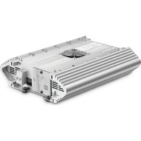
eStore
natural_image
Simple line drawing of a pen-like object with a curved top and internal cross-section (no text or symbols)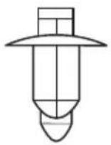
5
natural_image
Technical line drawing of a mechanical component with no visible text or symbols6
7
8
9

Please read this instruction manual carefully before installation and first use, and store it in a safe place. If you pass on the product to another person, hand over this instruction manual along with it.
Table of contents
1 Explanation of symbols 9
2 Safety instructions .... 10
3 Scope of delivery 11
4 Accessories 12
5 Intended use 13
6 Technical description ..... 14
7 Attaching eStore 16
8 Connecting eStore 17
9 Before initial use 22
10 Using eStore 22
11 Cleaning eStore 24
12 Troubleshooting 25
13 Warranty 28
14 Disposal 28
15 Technical data 29
1 Explanation of symbols

DANGER!
Safety instruction: Failure to observe this instruction will cause fatal or serious injury.

WARNING!
Safety instruction: Failure to observe this instruction can cause fatal or serious injury.

CAUTION!
Safety instruction: Failure to observe this instruction can lead to injury.

NOTICE!
Failure to observe this instruction can cause material damage and impair the function of the product.

NOTE
Supplementary information for operating the product.
▶ Action: This symbol indicates that action is required on your part. The required action is described step-by-step.
√This symbol describes the result of an action.
Fig. 1 5, page 3: This refers to an element in an illustration. In this case, item 5 in figure 1 on page 3.
2 Safety instructions
The manufacturer accepts no liability for damage in the following cases:
● Damage to the product resulting from mechanical influences and excess voltage or current
- Alterations to the product without express permission from the manufacturer
● Use for purposes other than those described in the operating manual
Note the following basic safety information when using electrical devices to protect against:
- Electric shock
- Fire hazards
- Injury
2.1 General safety

DANGER!
- In the event of fire, use a fire extinguisher which is suitable for electrical devices.

WARNING!
- Do not use the device if the device itself or its connection cables are visibly damaged.
- This device may only be repaired by qualified personnel. Inadequate repairs may cause serious hazards.
- Persons whose physical sensory or mental capacities prevent them from using this device safely should not operate it without the supervision of a responsible adult.
● Electrical devices are not toys!
Always keep and use the device out of the reach of children.
● Children must be supervised to ensure that they do not play with the device.

NOTICE!
- Check that the voltage specification on the type plate is the same as that of the power supply.
- Ensure that other objects cannot cause a short circuit on the contacts of the device.
- Ensure that the positive [+] and negative [-] terminals never come into contact.
- If cables have to be led through sharp-edged walls, use a cable duct or cable bushes!
- Do not lay any loose or sharp bent cables against electric-conducting materials (metal).
2.2 Operating the device safely

DANGER! Danger of electrocution!
- Do not touch exposed cables with your bare hands. This applies especially to connected devices using the AC mains.

WARNING!
- Only use the device in closed, well-ventilated rooms.

CAUTION!
- Do not operate the device
– In salty, wet or damp environments
– In the vicinity of corrosive fumes
– In the vicinity of combustible materials
– In areas where there is a danger of explosions.
- Do not pull on cables.
3 Scope of delivery
- eStore battery
● Installation and operating manual
4 Accessories
Available as accessories or spare parts (not included in the scope of delivery):
| Part designation Item number | |
| eStore BUS cable Kit | 9102900279 |
| RJ11 pin to pin and eStore ID decals | |
| For communication between eStore units in multiple eStores, when using eStore Bus | |
| eStore configuration kit | 9102900281 |
| Male – Male USB cable and CD | |
| For setup of multiple eStores – installers only | |
| eStore eCore BUS cable | 9102900280 |
| Cat5 LAN cable, RJ45 – pin to pin | |
| For communication between eStore and eCore | |
| eStore MPC01 BUS cable | 9102200197 |
| For communication between eStore and MPC01 | |
| eStore MCA BUS cable | 9103530048 |
| For communication between eStore and MCA chargers, when not using MPC01 | |
| Replacement fuse (250 A) | 9102900282 |
| Littelfuse Mega series, hole distance 50.8mm | |
| eStore mounting bracket kit – vertical | 9102900289 |
| For mounting eStore in vertical position | |
| eStore mounting bracket kit – horizontal | 9102900290 |
| For mounting eStore in horizontal position | |
5 Intended use
eStore serves as a voltage source of 12 V in power systems for caravans, campers, commercial vehicles and stationary applications. eStore may not be used for medical purposes.
In conjunction with an inverter, such as Dometic eCore, devices with 230 V\~ can be supplied.
Use as a starter battery is not possible. eStore must not be directly connected to the starter battery to support engine starting. Up to eight eStore can be connected in parallel to increase the total installed capacity up to 800 Ah.
eStore can be transported with the built-in handles.
6 Technical description
6.1 General description
eStore is a maintenance-free lithium-ion battery for 12 V---systems for power supply. It has an internal main switch and an internal 250 A fuse.
In conjunction with a battery management system eStore provides the following functions:
● Battery cell monitoring
● Battery voltage monitoring
● Battery cell temperature monitoring due to integrated temperature sensor
● Communication between multiple eStore batteries
eStore can be used with Dometic eCore or Waeco PerfectCharge MCA series chargers. Use of a third party charger is also permitted. To ensure the internal main switch remains closed when charging under normal conditions, the charger should have the following specification:
- end of charge voltage: between 13.8 V and 14.0 V
- maximum output: 40 A (30 A recommend), per installed eStore
To increase the total installed capacity, up to 8 eStores can be connected in parallel. The maximum combined output current must not exceed 250 A.

NOTE
A single eStore can provide current of 250 A for a short time. The continuous current should not exceed 200 A. Continuous discharge current exceeding 200 A from a single eStore can lead to a shorter lifetime. Use two or more eStores when current of more than 200 A is required continuously.
6.2 Display and operating elements
Pos. in
fig. 1, Description Explanation
page 3
1 Main Switch Command activates (closes) and disactivates (opens) the internal main switch
2 Status LED off: the battery management system is OFF due to storage mode or severe over discharge
flashes green: the battery management system is active, the main switch is activated or turned on (closed)
flashes yellow: the battery management system is active, the main switch is disactivated or turned off (open)
flashes red: malfunction
3 eStore-BUS interface
4 LIN interface for connection to Waeco PerfectCharge MCA chargers and Dometic MPC01
5 USB interface for eStore configuration
6 CAN-bus interface
6.3 Fuse and connections
Pos. in
fig. 2, Description Explanation
page 3
1 Negative pole M8 terminal for chargers and consumer
2 Internal fuse 250 A – mounting hole center distance
50.8 mm
3 Positive pole M8 terminal for chargers and consumer
7 Attaching eStore

WARNING!
Do not secure the eStore using straps, or similar, passing over the plastic eStore cover. This will result in damage to the unit.

NOTE
If you use multiple connected eStores: configure and mark eStore number on each eStore before installation in the vehicle, see chapter "Connecting multiple eStores" on page 19.
Observe the following instructions on installation location
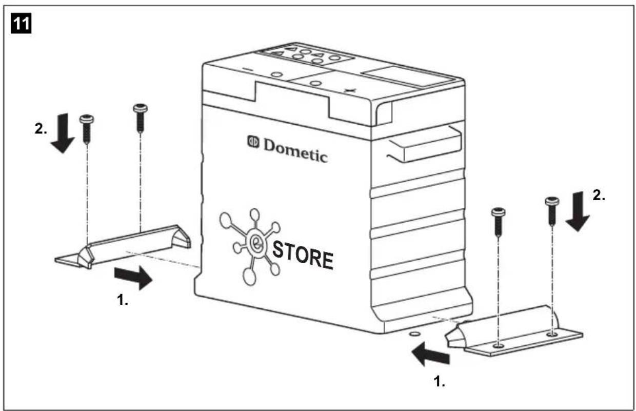
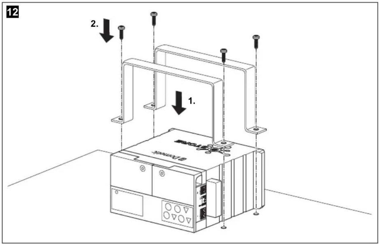
- eStore can be installed vertically (fig. 11, page 6) or horizontally (fig. 12, page 7), on a flat and stable surface.
● eStore must not be installed close to combustible materials.
● The installation location should be protected from moisture and dust. -
Leave at least 2 cm of space around eStore and ensure good ventilation. The installation should avoid low temperatures during winter operation (charging) to ensure continuous operation.
Avoid low temperatures during winter operation. -
For safety reasons, note the location of existing wiring harnesses, wires and other components within the installation area, in particular those which are not visible, when installing the eStore (when drilling or screwing etc.).
- If you install more than one eStore, leave at least 1 cm of space between the eStores.
▶ Select a suitable location and secure eStore safely.
▶ Vertical mounting: Use the integrated fixing feet to secure the eStore (fig. 11, page 6).
Suitable mounting brackets are available as accessories (see chapter "Accessories" on page 12).
▶ Horizontal mounting: Secure eStore with two straps or bands across the device (fig. 12, page 7). Pass them between the handles and mounting feet and fix them to the mounting surface. This will ensure the eStore does not move when the vehicle is in motion.
Suitable mounting brackets are available as accessories (see chapter "Accessories" on page 12).
8 Connecting eStore
8.1 Opening the cover of the pole
▶ Release the closure by gently pushing down the pin in the middle of the closure (fig. 3 1, page 3).
Take care not to push it through completely.
▶ Open the cover (fig. 3 2, page 3).
▶ Remove the unlocked closure (fig. 3 3, page 3).
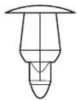
▶ Note the positions of the closure (fig. 4, page 4):
- 1 : unlocked
- 2: ready (armed)
- 3: locked
8.2 Closing the cover of the pole
▶Slide back the pin of the closure.
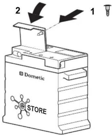
▶ Put in the ready (armed) closure (fig. 5 1, page 4).
▶ Close the cover(fig. 5 2, page 4).
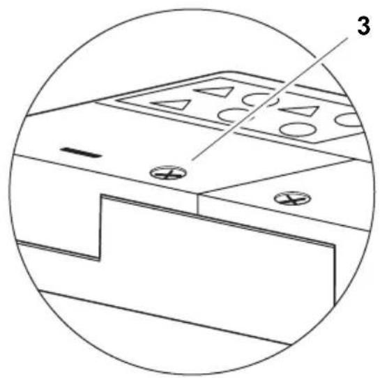
▶Lock the closure by gently pushing down the pin in the middle of the closure (fig. 5 3, page 4).
Take care not to push it through completely.
8.3 Activating eStore

NOTE
eStore is supplied in a storage mode that reduces self-discharge during storage. To use eStore, you must activate it first.
▶ Open the cover of the pole (see chapter “Opening the cover of the pole” on page 17).
▶ Connect positive pole (fig. 2 1, page 3) and negative pole (fig. 2 2, page 3) with a low output current, 12 V=== battery or charger.
√ The Status LED (fig. 1 2, page 3) flashes yellow.
√eStore ist activated.
8.4 Connecting the power cable

NOTICE!
- Only connect devices with a rated voltage of 12 V---.
- Pay attention to the correct polarity when connecting devices to eStore. Please refer to the respective manual.
● Make sure that the devices you want to connect are turned off.
▶ Turn off (open) the main switch of eStore one by pressing the main switch command (fig. 1 1, page 3).
▶Open the cover (see chapter “Opening the cover of the pole” on page 17).
▶ Connect the positive cable to the positive pole (fig. 2 3, page 3).
▶Tighten the terminal screw with a tightening torque of 13 to 15 Nm.
▶ Close the cover (see chapter “Closing the cover of the pole” on page 17.
▶ Open the cover of the negative pole (see chapter “Opening the cover of the pole” on page 17).
▶ Connect the negative cable to the negative pole (fig. 2 1, page 3).
▶Tighten the terminal screw with a tightening torque of 13 to 15 Nm.
▶Close the cover of the negative pole (see chapter “Closing the cover of the pole” on page 17).
▶Turn on (close) the main switch of the eStore by pressing the main switch command (fig. 1 1, page 3).
8.5 Connecting consumers
▶Turn off all devices, especially those that are connected with eStore.
▶ Turn off (open) the main switch of eStore one by pressing the main switch command (fig. 1 1, page 3).
▶ Connect the 12 V== device to eStore.
▶Turn on (close) the main switch of the eStore by pressing the main switch command (fig. 1 1, page 3).
▶ Turn on the 12 V== device.
8.6 Connecting data cable
You can connect eStore for data communication as follows:
● to Dometic eCore via the CAN bus
● to Waeco PerfectCharge MCA charger via LIN/CI bus
● to Waeco PerfectCharge MCA charger via LIN/CI bus, through Dometic MPC01
Through the data link parameters such as voltage, temperature and charge level are monitored and displayed. For more details, please refer to the relevant operating instructions of the connected devices.
▶ Establish a data connection corresponding to your system configuration.
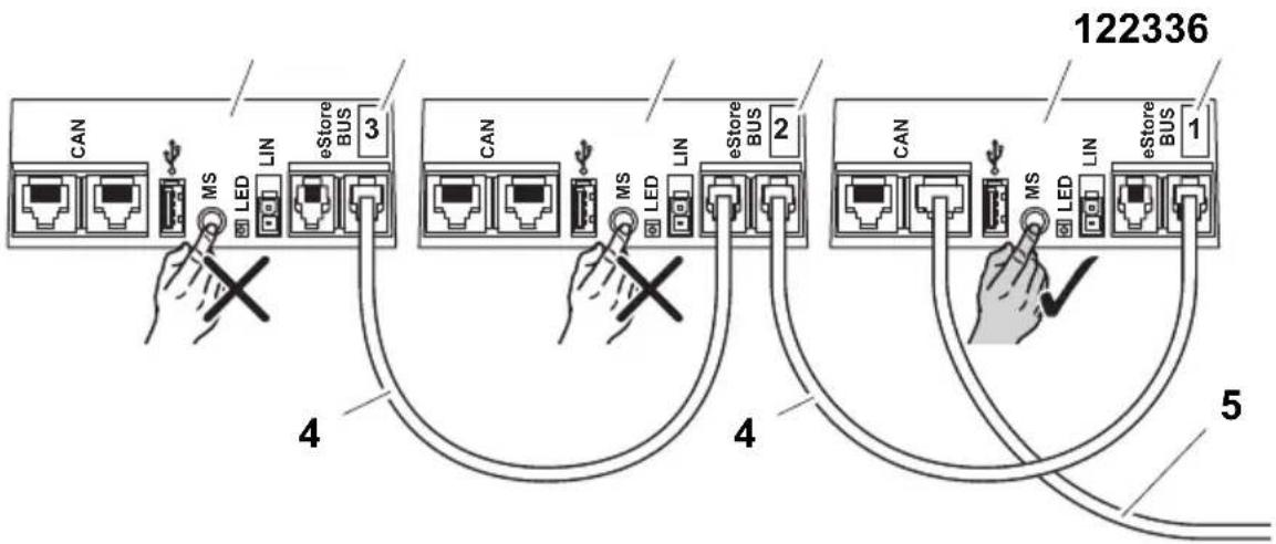
8.7 Connecting multiple eStores
Up to eight eStore can be connected in parallel to increase the total battery pack capacity to up to 800 Ah. The figure shows an example of the data connections for three connected eStores (fig. 6, page 4).

NOTE
- To connect multiple eStores, you need at least one BUS cable and the eStore configuration kit (see chapter “Accessories” on page 12).
- Connected eStores must be set with the eStore Configurator (see chapter "Connect BUS cable and configure" on page 20). If you only use a single eStore, no configuration is required. eStore is factory-adjusted to be used as a single battery.
● Make sure that all eStores are fully charged.
The first eStore serves as the master. It has the following functions:
- It controls the main switch of the other eStores (fig. 6, page 4).
- It connects to the chargers via data links (CAN/LIN).
The other eStores are controlled as slaves by the master.
Connect BUS cable and configure
For configuration you need a PC with a USB port and the eStore configurator.
Depending on the installation situation it may be useful to configure and tag each eStore before installation into the vehicle.
▶ Make sure that eStore is not in storage mode (status LED is blinking).
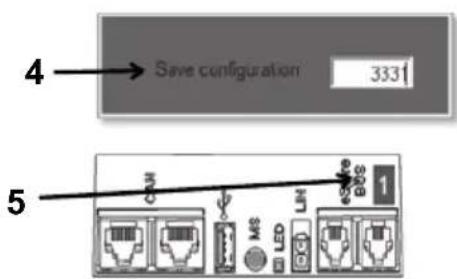
▶ Plug the USB cable from the PC into the USB port (fig. 1 5, page 3) of the first (master) eStore.
▶Configure the master, see chapter "Configuring connected eStores" on page 20.
▶ Attach the ID label (fig. 6 6, page 4) on the master (fig. 6 1, page 4).
▶Disconnect the USB cable from the master.
▶Plug the USB cable from the PC to the USB port of the first slave.
▶ Attach the ID label (fig. 6 3, page 4) on the slave (fig. 6 2, page 4).
▶Configure the remaining slaves, if necessary.
▶ Connect the eStores with the BUS cables (fig. 6 4, page 4).
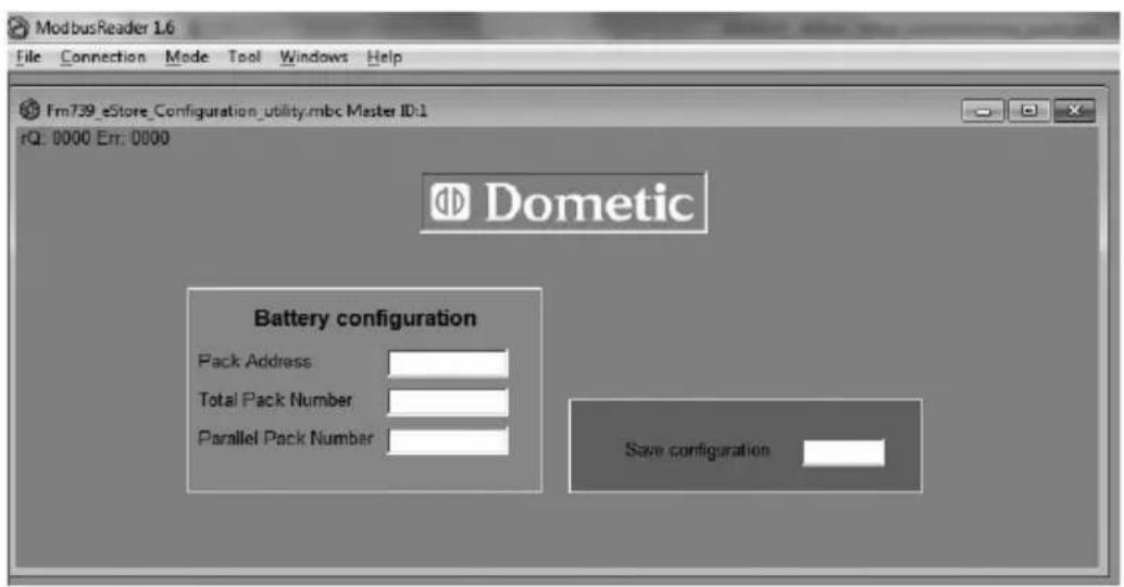
8.8 Configuring connected eStores
▶If necessary, install the ModbusReader "mbreader_setup.exe" from the data CD to your PC.
▶ Copy the file “eStore_Configuration_utility_FM739.mbc” of the data CD to the hard disk of the PC.
▶Open the file "eStore_Configuration_utility_FM739.mbc".
√ The eStore configurator opens (fig. 7, page 5).
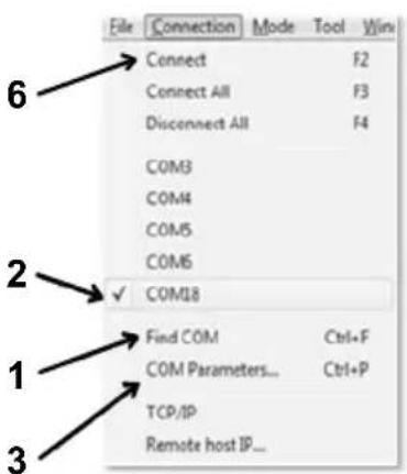
▶ Press CTRL + F or select in the menu “Connection” the command Find COM (fig. 8 1, page 5).
▶ Select the new port number, in the example COM18 (fig. 8 2, page 5).
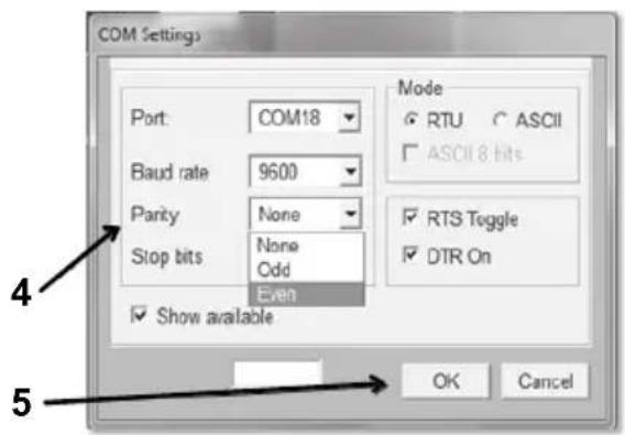
▶ Press CTRL + P or select in the menu “Connection” COM Parameters (fig. 8 3, page 5).
▶ The window COM Settings opens.
▶ Choose from the list Parity (fig. 8 4, page 5) the value Even.
▶ Click OK (fig. 8 5, page 5).
▶ Enter in the field Pack Address the number of the eStore, e.g. “1” for the master (fig. 9 1, page 5).
▶ Press “F2” or select in the menu “Connection” the command Connect (fig. 8 6, page 5).
▶Press the enter key.
▶ Enter in the field Total Pack Number the number of all eStores you want to connect, e.g. "3" if you want to connect three eStores (fig. 9 2, page 5).
▶Press the enter key.
▶ Enter in the field Parallel Pack Number the number of all eStores you want to connect, e.g. "3" if you want to connect three eStores (fig. 9 3, page 5).
Note: total pack number and parallel pack number must be the same.
▶Press the enter key.
▶ Enter the password 3331 (fig. 9 4, page 5).
▶Press the enter key.
▶ Attach the ID label (fig. 9 5, page 5).
Note: The number of the last eStore must be identical to the total number of eStore.

NOTE
For a more detail description of setup options with Dometic eCore, Dometic MPC01, Waeco PerfectCharge MCA chargers and other devices, please contact Dometic (see addresses on the back page).
9 Before initial use

NOTE
Make sure that the single or multiple eStores are fully charged after installation because a discharge may otherwise cause damage.
10 Using eStore

NOTICE!
Do not leave the eStore in a discharged state.
If the main switch opens due to over discharge, recharge eStore as soon as possible (maximum 5 days). Failure to recharge will cause eStore to enter storage mode and may result in damage to the eStore.

NOTE
Observe the following notes to prolong the life of the eStore:
- Avoid discharging eStore to the point at which the main switch opens (see chapter “Operating voltages and main switch” on page 23).
- Avoid storing or operating eStore at extremely high or low temperatures.
- Avoid continuously high discharge (> 200 A).
10.1 Operating voltages and main switch
The eStore Battery Management System (BMS) assesses the state of each cell in the battery, deciding when to protect the battery by opening the main switch.
The Main Switch works as follows:
eStore state Main Switch behavior
Discharging < 30 A, 11 – 12 V: main switch opens
30 A, 10 – 11.8 V: main switch opens These are indicative values and are given as guidance only. The main switch opening voltage depends on internal parameters such as cell voltage and temperature, and discharge current. The indicated current values are valid per single eStore.
Charging The main switch opening voltage depends on internal parameters such as cell voltage and temperature, and charge current. The maximum voltage above which the main switch opens is 15.2 V. Charging with the recommended charging parameters will ensure the main switch remains closed during normal operation. See chapter “Charging eStore” on page 23 for recommended charging parameters.
10.2 Charging eStore

NOTICE!
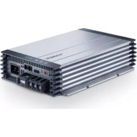
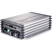
eStore can be charged with Dometic eCore or Waeco PerfectCharge MCA series chargers (choose power mode; see charger manual for appropriate DIP switch setting). Use of third party chargers is permitted. The main switch will remain closed when charging under normal conditions if the following charger parameters are met:
● end of charge voltage: between 13.8 V and 14.0 V
- maximum output 40 A (30 A recommend) per installed eStore For further information please contact Dometic (see addresses on the back page).

NOTE
Please also refer to the manual of the charger.
10.3 Changing the fuse

NOTE
Use a maximum 250 A fuse with 50.8 mm hole center distance.
Proceed as follows to replace the fuse:
▶ Open the cover of the positive pole (see chapter “Opening the cover of the pole” on page 17).
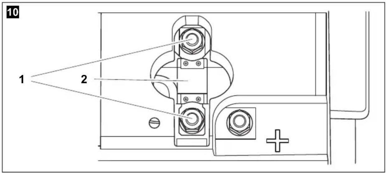
▶ Remove the nuts and washers from the fuse (fig. 10 1, page 6).
▶ Replace the fuse (fig. 10 2, page 6).
▶ Fix the new fuse with the nuts and washers (fig. 10 1, page 6). Tighten the nuts between 13 and 15 Nm.
▶Close the cover of the positive pole (see chapter “Closing the cover of the pole” on page 17).
10.4 Storing eStore

NOTE
- Store eStore in a cool dry place.
- Avoid storage in permanent high temperatures. This shortens the service life.
● Recharge eStore every 3 months.
● For long storage (e.g. RV winter break): - remove all loads
- charge eStore
- open the main switch
This will avoid over discharge and potential damage to eStore.
11 Cleaning eStore

NOTICE!
Do not use sharp or hard objects or cleaning agents for cleaning as these may damage the product.
▶Occasionally clean the product with a damp cloth.
12 Troubleshooting
| Problem Cause Remedy | ||
| No voltage at the battery terminals. | The main switch is turned off (open). | ►Turn on (close) the main switch. |
| The fuse is defective. ►Replace the fuse (see chapter “Changing the fuse” on page 24). | ||
| eStore is in storage mode. ►Activate eStore. | ||
| eStore is not configured correctly. | ►Configure eStore. | |
| eStore is over discharged. ►Charge eStore with a charging current of < 10 A.Note: Do not use intelligent charging systems (with main swtich open, the eStore terminals have no voltage. Some intelligent battery chargers do not start if no voltage is present).►Contact an authorised workshop. | ||
| eStore is defective. ►Contact an authorised workshop. | ||
| Status LED does not flash. | eStore is in storage mode. ►Activate eStore. | |
| eStore is severely over discharged. | ►Charge eStore with a charging current of < 10 A.Note: Do not use intelligent charging systems (with main swtich open, the eStore terminals have no voltage. Some intelligent battery chargers do not start if no voltage is present).►Contact an authorised workshop. | |
| eStore is defective. ►Contact an authorised workshop. | ||
Problem Cause Remedy
| Status LED flashes red. | eStore is configured to be connected to multiple eStores and BUS cables are not plugged in. | ►Plug in eStore cables. |
| eStore is over discharged. ►Charge eStore. | ||
| eStore is over charged ►Disconnect chargers from eStore. ►Check the charging voltage of battery chargers. | ||
| eStore ist defective. ►Contact an authorised work-shop. | ||
| eStore does not respond to pressing of the main switch command. | eStore is in storage mode. ►Activate eStore. | |
| eStore is over discharged. ►Charge eStore with a charging current of < 10 A. Note: Do not use intelligent charging systems (with main switch open, the eStore terminals have no voltage. Some intelligent battery chargers do not start if no voltage is present). ►Contact an authorised work-shop. | ||
| eStore is configured as slave and not as master. | ►Use main switch command on master eStore (eStore configured #1) | |
| Configuration for connecting multiple eStores is faulty. | ►Check the configuration. | |
| eStore is defective. ►Contact an authorised work-shop. | ||
Problem Cause Remedy
| Main switch turns on (closes) but turns off (opens) again immediately. | eStore is over discharged. ▶Charge eStore. | |
| eStore is over charged ▶Disconnect chargers from eStore. ▶Check the charging voltage of battery chargers. | ||
| Charge current is too high. ▶Reduce charge current. | ||
| Discharge current is too high. ▶Reduce the load. ▶Check the temperature of the eStore. ▶Charge eStore. | ||
| eStore is defective. ▶Contact an authorised work-shop. | ||
| "Warning eStore" appears on eCore control panel. | eStore temperature is too low for charging. | ▶Check charger status LED. ▶Check eStore Temperature. ▶Heat eStore storage area. |
| eStore temperature is too high for charging. | ▶Check charger status LED. ▶Check eStore Temperature. ▶Heat eStore storage area. | |
13 Warranty
The statutory warranty period applies. If the product is defective, please contact the manufacturer's branch in your country (see the back of the instruction manual for the addresses) or your retailer.
For repair and guarantee processing, please include the following documents when you send in the device:
● A copy of the receipt with purchasing date
● A reason for the claim or description of the fault
14 Disposal
▶Place the packaging material in the appropriate recycling waste bins wherever possible.
If you wish to finally dispose of the product, ask your local recycling centre or specialist dealer for details about how to do this in accordance with the applicable disposal regulations.

Protect the environment!
Do not dispose of any batteries with general household waste. Return defective or used batteries to your retailer or dispose of them at collection points.
15 Technical data
| eStore | |
| Item No.: 9102900224 | |
| Rated voltage: 13.2 V--- | |
| Operating temperature range (for discharging): | -30 °C (with reduced performance) to +55 °C |
| Temperature range for charging with Dometic eCore: with other chargers: | -10 °C to +55 °C0 °C to +40 °C |
| Rated capacity: 100 Ah | |
| Dimensions L x W x H: | 315 x 160 x 285 mm |
| Weight: 17 kg | |
| Inspection/Certification: |  |
| IEC 62133UN 38.3UN 3480 |
6 Description technique
Dometic Australia Pty. Ltd.
1 John Duncan Court
Varsity Lakes QLD 4227
1800 212121
+61 7 55076001
Mail: sales@dometic-waeco.com.au
AUSTRIA
Dometic Austria GmbH
The Gateway · 25 Canton Road,
Tsim Sha Tsui · Kowloon
+852 24611386
+852 24665553
Mail: info@dometic-waeco.com.hk
HUNGARY
Dometic Plc. Sales Office
Kerékgyártó u. 5.
H-1147 Budapest
+36 1 468 4400
昌 +36 1 468 4401
Dometic Italy S.r.l.
Via Virgilio, 3
I-47100 Forli
+39 0543 754901
+39 0543 756631
Mail: info@dometic.it
NORWAY
Dometic Norway AS
Skolmar 24
N-3232 Sandefjord
+47 33428450
吕 +47 33428459
Mail: firmapost@waeco.no
POLAND
Dometic Poland Sp. z o.o.
Ul. Puławska 435A
02-801 Warszawa
+48 22 414 32 00
+48 22 414 32 01
Mail: info@dometic.pl
RUSSIA
Dometic RUS LLC
Komsomolskaya square 6-1
107140 Moscow
+7 495 780 79 39
+7 495 916 56 53
Mail: info@dometic.ru
SLOVAKIA
Dometic Slovakia Sales Office Bratislava
Nádražná 34/A
SK-900 28 Ivanka pri Dunaji
+421 2 45 529 680
Mail: bratislava@dometic.com
SPAIN
Dometic Spain S.L.
Avda. Sierra del Guadarrama, 16
E-28691 Villanueva de la Cañada
Madrid
+34 902 111 042
+34 900 100 245
Mail: info@dometic.es
SWEDEN
Dometic Scandinavia AB
Gustaf Melins gata 7
Dometic Switzerland AG
Riedackerstrasse 7a
CH-8153 Rümlang (Zürich)
+41 44 8187171
吕 +41 44 8187191
Mail: info@dometic-waeco.ch
TAIWAN
WAECO Impex Ltd.
Taipei Office
9F.-10, No. 1180, Zhongzheng Rd.,
Zhonghe Dist., New Taipei City 23586
+886 2 22237225
昌 +886 2 81926742
Mail: marketing@waeco.com.tw
UNITED KINGDOM
Dometic UK Ltd.
Dometic House · The Brewery
Blandford St. Mary
Dorset DT11 9LS
+44 844 626 0133
昌 +44 844 626 0143
Mail: sales@dometic.co.uk
UNITED ARAB EMIRATES
Dometic Middle East FZCO
P. O. Box 17860
S-D 6, Jebel Ali Freezone
Dubai
+971 4 883 3858
+971 4 883 3868
Mail: info@dometic.ae
UNITED STATES OF AMERICA
Dometic Marine Division
2000 N. Andrews Ave. Extension
Pompano Beach, FL 33069 USA
+1 954 973 2477
+1 954 979 4414
Mail: marinesales@dometicusa.com

- Table of contents
- Explanation of symbols
- DANGER!
- WARNING!
- CAUTION!
- NOTICE!
- NOTE
- Safety instructions
- General safety
- Operating the device safely
- DANGER! Danger of electrocution!
- Scope of delivery
- Accessories
- Intended use
- Technical description
- General description
- Display and operating elements
- Fuse and connections
- Attaching eStore
- Observe the following instructions on installation location
- Connecting eStore
- Opening the cover of the pole
- Closing the cover of the pole
- Activating eStore
- Connecting the power cable
- Connecting consumers
- Connecting data cable
- Connecting multiple eStores
- Connect BUS cable and configure
- Configuring connected eStores
- Before initial use
- Using eStore
- Operating voltages and main switch
- eStore state Main Switch behavior
- Charging eStore
- Changing the fuse
- Storing eStore
- Cleaning eStore
- Troubleshooting
- Warranty
- Disposal
- Protect the environment!
- Technical data
- Description technique
- Dometic Australia Pty. Ltd.
- AUSTRIA
- Dometic Austria GmbH
- HUNGARY
- Dometic Plc. Sales Office
- Dometic Italy S.r.l.
- NORWAY
- Dometic Norway AS
- POLAND
- Dometic Poland Sp. z o.o.
- RUSSIA
- Dometic RUS LLC
- SLOVAKIA
- Dometic Slovakia Sales Office Bratislava
- SPAIN
- Dometic Spain S.L.
- SWEDEN
- Dometic Scandinavia AB
- Dometic Switzerland AG
- TAIWAN
- WAECO Impex Ltd.
- UNITED KINGDOM
- Dometic UK Ltd.
- UNITED ARAB EMIRATES
- Dometic Middle East FZCO
- UNITED STATES OF AMERICA
- Dometic Marine Division
Brand : DOMETIC
Model : EStore
Category : Battery charger