
KGV300 - Boiler GORENJE - Free user manual and instructions
Find the device manual for free KGV300 GORENJE in PDF.
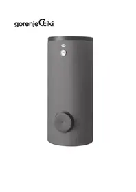

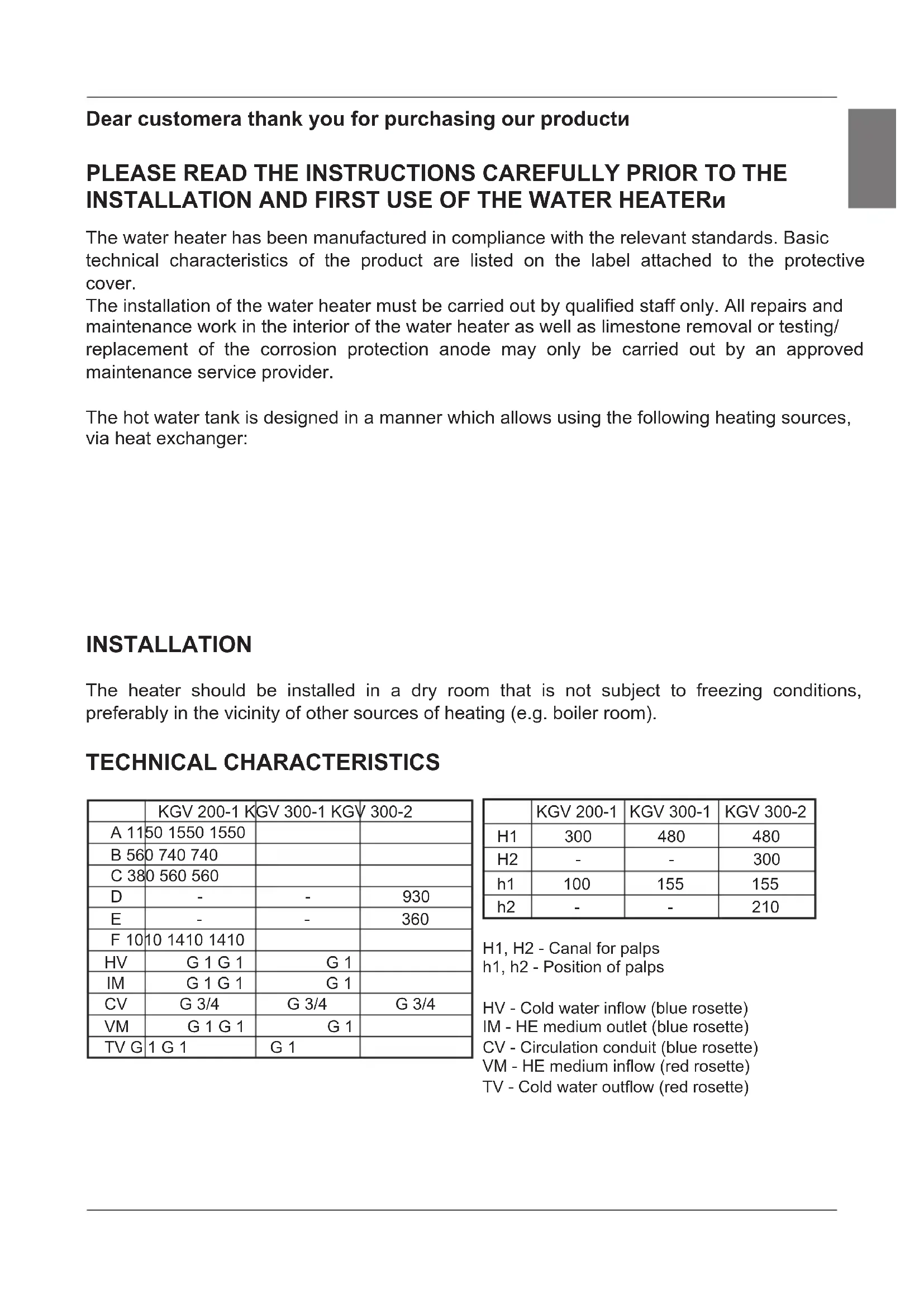


| Product type | Domestic hot water storage tank |
| Brand | Gorenje |
| Model | KGV300 |
| Capacity | 285 liters (KGV 300-1) |
| Net weight / gross weight | 112 kg / 397 kg |
| Dimensions (height × width × depth) | Approximately 1550 × 740 × 560 mm (depending on model KGV 300-1) |
| Insulation | 57 mm, IP21 protection class |
| Anti-corrosion protection | Vitreous enamel + magnesium anode |
| Heat exchanger surface area | 1.6 m² (lower heat exchanger) |
| Heat exchanger volume | 10 liters |
| Maximum operating pressure | 0.5 MPa (5 bar) |
| Connections | Cold water (G1), hot water (G1), circulation (G3/4), heat exchanger inlet/outlet (G1) |
| Compatible heating sources | Boiler, solar energy, heat pump |
| Possibility of additional electric heating element | Yes, type R (flange Ø180 mm) or type SH (socket G6/4) |
| Recommended maintenance | Anode check every 2 years, descaling according to water quality |
Frequently Asked Questions - KGV300 GORENJE
User questions about KGV300 GORENJE
0 question about this device. Answer the ones you know or ask your own.
Ask a new question about this device
Download the instructions for your Boiler in PDF format for free! Find your manual KGV300 - GORENJE and take your electronic device back in hand. On this page are published all the documents necessary for the use of your device. KGV300 by GORENJE.
USER MANUAL KGV300 GORENJE
Dear customer, thank you for purchasing our product.
PLEASE READ THE INSTRUCTIONS CAREFULLY PRIOR TO THE INSTALLATION AND FIRST USE OF THE WATER HEATER.
The water heater has been manufactured in compliance with the relevant standards. Basic technical characteristics of the product are listed on the label attached to the protective cover.
The installation of the water heater must be carried out by qualified staff only. All repairs and maintenance work in the interior of the water heater as well as limestone removal or testing/replacement of the corrosion protection anode may only be carried out by an approved maintenance service provider.
The hot water tank is designed in a manner which allows using the following heating sources, via heat exchanger:
INSTALLATION
The heater should be installed in a dry room that is not subject to freezing conditions, preferably in the vicinity of other sources of heating (e.g. boiler room).
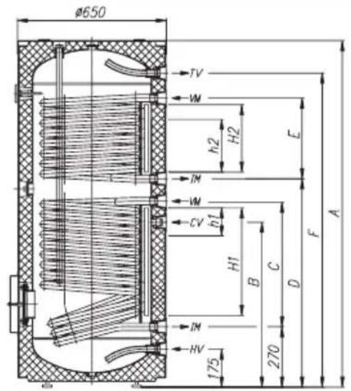
TECHNICAL CHARACTERISTICS
| KGV 200-1 KGV 300-1 KGV 300-2 | |||
| A 11 | 50 1550 1550 | ||
| B 56 | 0 740 740 | ||
| C 38 | 0 560 560 | ||
| D | - | - | 930 |
| E | - | - | 360 |
| F 10 | 10 1410 1410 | ||
| HV | G 1 G 1 | G 1 | |
| IM | G 1 G 1 | G 1 | |
| CV | G 3/4 | G 3/4 | G 3/4 |
| VM | G 1 G 1 | G 1 | |
| TV G | 1 G 1 | G 1 | |
| KGV 200-1 | KGV 300-1 | KGV 300-2 | |
| H1 | 300 | 480 | 480 |
| H2 | - | - | 300 |
| h1 | 100 | 155 | 155 |
| h2 | - | - | 210 |
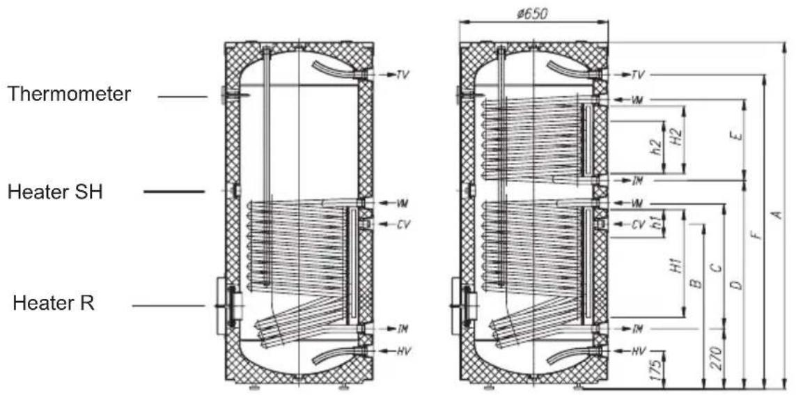
H1, H2 - Canal for palps
h1, h2 - Position of palps
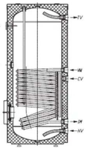
HV - Cold water inflow (blue rosette)
IM - HE medium outlet (blue rosette)
VM - HE medium inflow (red rosette)
TV - Cold water outflow (red rosette)
| Type KGV 200-1 KGV 300-1 KGV 300-2 | |||
| Volume [I] 200 | 285 280 | ||
| Rated pressure [MPa] 0,6 | |||
| Weight / Filled with water [kg] 82 | / 282 112 / 397 | 134 / 414 | |
| Anti-corrosion protection of tank Enameded/Mg Anode | |||
| HE heated surface - lowe [m²] | 1,05 | 1,6 | 1,6 |
| HE heated surface - upper [m²] | - | - | 1,09 |
| HE volume - lower [l] | 6,6 | 10 | 10 |
| HE volume - upper [l] | - | - | 6,8 |
| insulation thickness [mm] 57 | |||
| Degree of protection IP 21 | |||
HE - Heat exchanger
On the rear side of the hot water tank there are special channels (H1, H2) for mounting the feelers for regulation of the system connection of the hot water tank to other heating sources. Access to the channels is under the covering joint of the protective covering, approximately in the middle of the tank height.
Insert the feeler into the channel and fix it with the enclosed rubber tap. Recommended position (h1, h2) of the feeler is marked on the drawing:
- If the feeler is mounted higher than recommended, the thermostat will react too fast, the operating time of the circular pump will be shorter and the difference between the temperature in the hot water tank and heating media after the thermostat switch off will be higher. This means that the quantity of water in the hot water tank and its temperature will be lower,
- If the feeler is mounted lower than recommended, the operating time of the circular pump will be longer and the difference between the temperature in the hot water tank and heating media after the thermostat switch off will be lower. This means that the quantity of water in the hot water tank and its temperature will be little higher.
CONNECTION TO THE WATER SUPPLY
Before connecting the hot water tank, install the protective covering. Take off the top cover and insert the covering, make sure the slots on the covering match the connections on the hot water tank. Zip the zipper from top to bottom and tighten the tapes on the top edge of the covering. Replace the top cover. Insert the thermometer into the prefabricated sleeve on the front of the hot water tank; make sure to cut the opening for the sleeve into the covering. The connection to water supply network and fastening of the coloured rosettes shall be made according to the markings defined in previous Section.
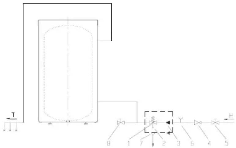
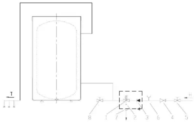
For safety reasons the supply pipe must be fitted with a return safety valve that prevents the pressure in the tank from exceeding nominal pressure by more than 0.1MPa . The heating of water in the heater causes the pressure in the tank to increase to the level set by the safety valve. As the water cannot return to the water supply system, this can result in dripping from the outflow of the safety valve. The drip can be piped into the drain by installing a catching unit just below the safety valve. The drainpipe fitted under the safety valve outflow must be piped down in a straight vertical line and located in an environment free from the onset of freezing conditions.
In case the existing plumbing does not enable you to pipe the dripping water from the return safety valve into the drain, you can avoid the dripping by installing expansion tank on the inlet water pipe of the boiler. The volume of the expansion vessel shall be at least 3% of the volume of the hot water tank.
Key:
- Return safety valve
- Test valve
- Non-return valve
- Pressure-reducing valve
- Stop valve
- Test unit
- Funnel outlet to the drain
- Drain valve
H - Cold water
T - Hot water
The water heater may be connected to the household water supply system without a pressure-reducing valve provided the supply mains pressure is less than 0.5MPa .
In case of the mains pressure exceeding 0.5MPa , a pressure-reducing valve must be installed to ensure that the pressure on the supply side of the heater does not rise above the nominal value.

CONNECTION TO ALTERNATIVE SOURCES OF HEATING
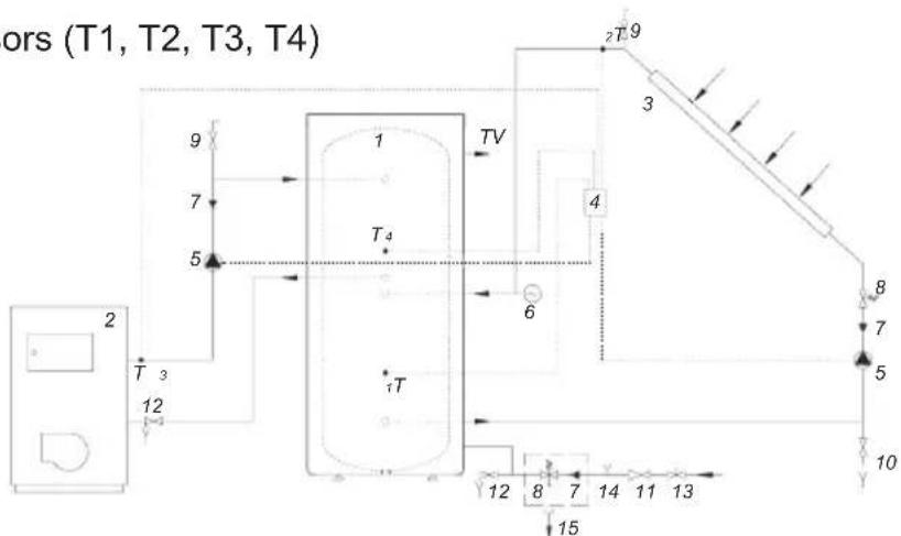
The heaters enable the water for sanitary use to be heated by alternative sources of energy (e.g. central heating, solar power, ...) by installing one or two heat exchangers.
Additionally, a heating pump may also be fitted to the side flange of the tank.
Options for connecting the water heater to various sources of heating are shown in the drawings below.
Connection to solar panels
Connection to the
central heating hot-water system
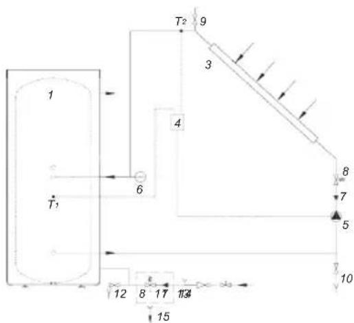
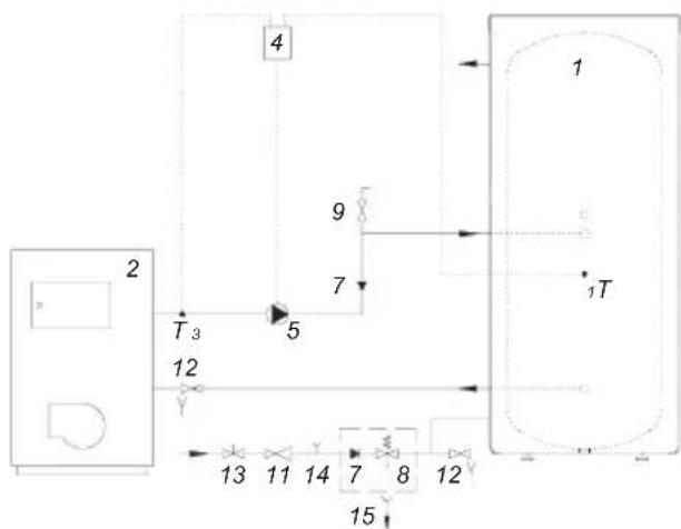
- Water heater
- Central heating hot-water system
- Solar panel
- Differential thermostat with sensors (T1, T2, T3, T4)
- Bypass pump
- Expansion tank
- Non-return valve
- Safety valve
- Air relief valve
- Fill/drain valve
- Reduction valve
- Drain valve
- Stop valve
- Test unit
- Funnel outlet to the drain
The water heater is ready for use once it has been connected to water and other sources of heating.
The usual main sources of heating of water for sanitary use are central heating or solar power; in this case any regulation of water heating is performed in the heating system.
- If you need higher temperature of water than assured by other heating sources,
- If due to seasonal or other conditions there are no main heating sources.
In case of exposure to sub-zero temperatures, the water should be thoroughly drained from the heater before the onset of freezing conditions.
Once that is done, open the hot water tap on one of the mixer taps connected to the water heater. The water from the water heater drains by way of the drain valve on the inlet pipe.
External parts of the water heater may be cleaned with a mild detergent solution. Do not use solvents and abrasive cleaners.
Regular preventive maintenance inspections ensure faultless performance and long life of your heater. The first of these inspections should be carried out by an authorised maintenance service provider about two years from the date of installation in order to inspect the wear of the corrosion protection anode and to remove any limestone as required. Build-up of limestone is a product of quality, quantity and temperature of water flowing through the water heater. While inspecting the heater, the maintenance service provider will also recommend the date of the next inspection.
Wear of the corrosion protection anode is carried out visually. Replacement is required when the inspection reveals that the anode diameter has been substantially reduced or worn all the way to the steel core.
Tank warranty is subject to regular inspections of the protective anode.
In the event of the water heater breaking down you are kindly requested to contact the authorised maintenance service provider located closest to you. Please do not attempt to repair the unit yourself.
Dear customer, thank you for purchasing our product.
PLEASE READ THE INSTRUCTIONS CAREFULLY BEFORE INSTALLATION AND FIRST USE OF THE WATER HEATER.
The water heater is manufactured in accordance with applicable standards. Its basic technical characteristics are indicated on the rating plate affixed to the protective cover.
Dear customer, thank you for purchasing our product.
Before using the boiler, read the instructions carefully!
The boiler has been manufactured in accordance with relevant standards. Its main technical characteristics are listed on the nameplate attached to the protective cover. The boiler may only be used by qualified personnel. Any work inside the boiler for repairs, descaling, or checking or replacing the anti-corrosion anode must be carried out only by authorized service personnel.
The hot water tank is designed so that, with the help of a heating element, we can use the following heat sources:
- Central heating system, - solar energy, - heat pump.
In the hot water tank, we can additionally install an electric heater type R with a connection of 0180 mm or an electric heater type SH with a connection of G 6/4.
CONTROL
Place the boiler in a dry room where it does not freeze, preferably near other heat sources (e.g., in a laundry room).
TECHNICAL CHARACTERISTICS OF THE BOILER
| KGV 200-1 KGV 300-1 KGV 300-2 | |||
| A 1150 1550 1550 | |||
| B 560 740 740 | |||
| C 380 560 560 | |||
| D | - | - | 930 |
| E | - | - | 360 |
| F 1010 1410 1410 | |||
| HV | G 1 G 1 | G 1 | |
| IM | G 1 G 1 | G 1 | |
| CV | G 3/4 | G 3/4 | G 3/4 |
| VM | G 1 G 1 | G 1 | |
| TV G | 1 G 1 | G 1 | |
| KGV 200-1 | KGV 300-1 | KGV 300-2 | |
| H1 | 300 | 480 | 480 |
| H2 | - | - | 300 |
| h1 | 100 | 155 | 155 |
| h2 | - | - | 210 |
H1, H2 - connections for sensors
DO NOT ALLOW CHILDREN TO OPERATE THE DEVICE!
The water heater is manufactured in accordance with applicable standards. The main technical characteristics are given in the data table, which is located on the back cover.
The installation of the water heater must be carried out only by qualified professionals. All repair and maintenance work on the device, including replacement of the magnesium anode, must be performed only by professionals from an authorized Gorenje service center.
The water heater is designed in such a way that, with the help of a heat exchanger:
- Central heating system, solar collector
- heat pump.
A storage water heater can be connected to a heating system via a transition piece of 180 mm diameter or an electric heating element on the bushing G 6/4.
INSTALLATION
The water heater should be installed in a dry and warm room, where there are no freezing conditions, preferably near other heat sources (e.g., boiler room).
TECHNICAL CHARACTERISTICS
| KGV 200-1 KGV 300-1 KGV 300-2 | |||
| A 11 | 50 1550 1550 | ||
| B 56 | 0 740 740 | ||
| C 38 | 0 560 560 | ||
| D -- | 930 | ||
| E -- | 360 | ||
| F 10 | 10 1410 1410 | ||
| HV G | 1 G 1 | G 1 | |
| IM | G 1 G 1 | G 1 | |
| CV | G 3/4 | G 3/4 | G 3/4 |
| VM | G 1 G 1 | G 1 | |
| TV G | 1 G 1 | G 1 | |
| KGV 200-1 | KGV 300-1 | KGV 300-2 | |
| H1 | 300 | 480 | 480 |
| H2 | - | - | 300 |
| h1 | 100 | 155 | 155 |
| h2 - | - | 210 | |
H1, H2 - sensor channels
h1, h2 - sensor positions
TV - heat exchanger (red socket)
Thermometer
Heating element SH
Heating element R
| Тип KGV 200-1 KGV 300-1 KGV 300-2 | |||
| ОБ'EMS [I] 200 285 280 | |||
| Номінальни ТИСК [MPa] 0,6 | |||
| Маса / наразовенiy ВODОу [kg] 82 / | 282 112 / 397 | 134 / 414 | |
| Аntникорозий засост kaЗанаЕмальованe / Магиевий anod | |||
| Плоба НарривTO - похни [m²] | 1,05 | 1,6 | 1,6 |
| Плоба НарривTO - ворхни [m²] | - | - | 1,09 |
| ОБ'ем TO - похни [I] | 6,6 | 10 | 10 |
| ОБ'ем TO - ворхни [I] | - | - | 6,8 |
| Товшина iазяцii [mm] 57 | |||
| Ровень зассту вд Вологи IP 21 |
TO - heat exchanger
On the rear side of the storage water heater, channels for sensors (H1, H2) are made, into which sensors for remote control of the water heater system with other heat sources can be inserted. Access to the channels is under the cover on the rear housing, approximately at the middle height of the storage water heater.
Insert the sensor into the channel and secure it. The recommended sensor positions (h1, h2) in the channels are shown in the diagram:
- If the sensor is secured above the recommended position, the thermostat will activate later, the circulation pump runtime will be shorter, the difference between the water temperature in the storage tank and the heating temperature will be higher, and after the thermostat is triggered, the quantity and temperature of water in the storage tank will be lower. If the sensor is secured below the recommended position, the circulation pump runtime will be longer, the difference between the water temperature in the storage tank and the heating temperature will be lower, and after the thermostat is triggered, the quantity and temperature of water in the storage tank will be higher.
CONNECTION TO THE WATER SUPPLY
The water heater must be filled with water before turning on the power. First, open the hot water tap and fill the water heater until water flows from the hot water tap, ensuring that the heating element is completely submerged. Close the drain valve at the bottom of the tank, then close the hot water tap and tighten the nut on the top of the tank. Replace the top cover. The thermometer is inserted into a specially designed hole on the front side of the water heater, where it may be necessary to make a corresponding cut in the protective cover. Connection to the water supply and electrical outlets must be done according to the instructions in the previous chapter.
For safety, the inlet pipe must be equipped with a non-return valve, which prevents the pressure in the tank from exceeding the nominal pressure by more than 0.1 MPa. The water heater is connected to the water supply, and the pressure in the tank rises to the level set by the non-return valve. Since water cannot flow back into the water supply system, it may cause water to drip from the outlet of the non-return valve. The outlet can be directed to a drain or a container, which must be placed below the non-return valve. The drain pipe, installed under the outlet opening of the non-return valve, must be in a strictly vertical position and in a room free from frost. In case the water supply and sewage system does not allow the installation of a water drainage system from the non-return valve, you can eliminate the dripping by installing an expansion tank on the inlet pipe for water. The volume of the expansion tank must be at least 3% of the volume of the water heater.
The water heater can be connected to the water supply network without a pressure reducing valve if the pressure in the network is less than 0.6 MPa. In case the working pressure exceeds 0.5 MPa, a pressure reducing valve must be installed to prevent exceeding the nominal pressure value of the water supply.
Description:
1. Safety valve 2. Control valve 3. Non-return valve 4. Pressure reducing valve 5. Shut-off valve 6. Control unit 7. Drain outlet 8. Drain valve
H - Cold water
T - Hot water outlet


- DEAR CUSTOMER, THANK YOU FOR PURCHASING OUR PRODUCT
- PLEASE READ THE INSTRUCTIONS CAREFULLY PRIOR TO THE INSTALLATION AND FIRST USE OF THE WATER HEATER
- INSTALLATION
- TECHNICAL CHARACTERISTICS
- HE - HEAT EXCHANGER
- CONNECTION TO THE WATER SUPPLY
- KEY
- CONNECTION TO ALTERNATIVE SOURCES OF HEATING
- PLEASE READ THE INSTRUCTIONS CAREFULLY BEFORE INSTALLATION AND FIRST USE OF THE WATER HEATER
- BEFORE USING THE BOILER, READ THE INSTRUCTIONS CAREFULLY
- CONTROL
- TECHNICAL CHARACTERISTICS OF THE BOILER
- TO - HEAT EXCHANGER
- DESCRIPTION
Brand : GORENJE
Model : KGV300
Category : Boiler