
DDLT PinControl 21 - Heating AEG - Free user manual and instructions
Find the device manual for free DDLT PinControl 21 AEG in PDF.
| Product type | Hydraulically controlled electric instantaneous water heater |
| Brand | AEG |
| Model | DDLT PinControl 21 |
| Category | Heating / Water heater |
| Dimensions (H x W x D) | 485 x 226 x 93 mm |
| Weight | 3.6 kg |
| Power supply | 400 V / 50 Hz, three-phase (3/PE) |
| Rated power | 21 kW |
| Rated current | 31 A |
| Recommended electrical protection | 32 A |
| Protection rating | IP25 (IP24 for surface mounting) |
| Protection class | 1 |
| Maximum admissible pressure | 1 MPa (10 bar) |
| Maximum incoming water temperature | 25 °C |
| Specific water resistivity (at 15°C) | ≥ 900 Ω·cm |
| Heating system | Bare wire |
| Power levels | 2 (stage I and II) |
| Trigger flow rate (stage I / II) | 3.5 / 5.6 l/min |
| Domestic hot water capacity (at 38°C, Δθ 26 K) | Approximately 11.1 l/min |
| Hydraulic connections | G 1/2 A (male thread) |
| Main functions | Flow regulation, safety pressure switch, frost protection |
| Maintenance | Cleaning with damp cloth, descaling, filter cleaning |
| Safety | Multi-pole cut-off, earthing, burn protection |
Frequently Asked Questions - DDLT PinControl 21 AEG
User questions about DDLT PinControl 21 AEG
0 question about this device. Answer the ones you know or ask your own.
Ask a new question about this device
Download the instructions for your Heating in PDF format for free! Find your manual DDLT PinControl 21 - AEG and take your electronic device back in hand. On this page are published all the documents necessary for the use of your device. DDLT PinControl 21 by AEG.
USER MANUAL DDLT PinControl 21 AEG
Hydraulically controlled instantaneous water heater
Operation and Installation 16
- General information 17
- Safety 17
- Appliance description.. 18
- Settings. 18
- Cleaning, care and maintenance 19
- Troubleshooting 19
INSTALLATION
- Safety 20
- Appliance description.. 20
9.Preparations 20 - Installation 21
- Commissioning 24
- Shutting down the system 24
- Troubleshooting 24
- Maintenance 25
- Specification 25
WARRANTY
ENVIRONMENT AND RECYCLING
SPECIAL INFORMATION
The appliance may be used by children aged 8 and up and persons with reduced physical, sensory or mental capabilities or a lack of experience and know-how, provided that they are supervised or they have been instructed on how to use the appliance safely and have understood the resulting risks. Children must never play with the appliance. Children must never clean the appliance or perform user maintenance unless they are supervised.
- Risk of scalding: The tap can reach temperatures in excess of 60°C .
- Ensure the appliance can be separated from the power supply by an isolator that disconnects all poles with at least 3mm contact separation.
- Secure the appliance as described in chapter "Installation / Installation".
Observe the maximum permissible pressure (see chapter "Specification / Data table"). - Drain the appliance as described in chapter "Installation / Maintenance / Draining the appliance".
OPERATION
1. General information
The chapters "Special Information" and "Operation" are intended for both the user and qualified contractors.
The chapter "Installation" is intended for qualified contractors.

Note
Read these instructions carefully before using the appliance and retain them for future reference.
Pass on the instructions to a new user if required.
1.1 Safety instructions
1.1.1 Structure of safety instructions

KEYWORD Type of risk
Here, possible consequences are listed that may result from failure to observe the safety instructions.
» Steps to prevent the risk are listed.
1.1.2 Symbols, type of risk
| Symbol Type of risk | |
| ! | Injury |
| Electrocution | |
| Burns (burns, scalding) | |
1.1.3 Keywords
| KEYWORD | Meaning |
| DANGER | Failure to observe this information will result in serious injury or death. |
| WARNING | Failure to observe this information may result in serious injury or death. |
| CAUTION | Failure to observe this information may result in non-serious or minor injury. |
1.2 Other symbols in this documentation

Note
General information is identified by the symbol shown on the left.
» Read these texts carefully.
| Symbol Meaning | |
| ! | Material losses (appliance damage, consequential losses and environ- mental pollution) |
| Appliance disposal | |
» This symbol indicates that you have to do something. The action you need to take is described step by step.
1.3 Units of measurement

Note
All measurements are given in mm unless stated otherwise.
2. Safety
2.1 Intended use
This appliance is intended for domestic use. It can be used safely by untrained persons. The appliance can also be used in a non-domestic environment, e.g. in a small business, as long as it is used in the same way.
This pressure appliance is designed to heat DHW. The appliance can supply one or more draw-off points.
Any other use beyond that described shall be deemed inappropriate. Observation of these instructions and of instructions for any accessories used is also part of the correct use of this appliance.
2.2 General safety instructions

CAUTION Burns
During operation, the tap can reach temperatures in excess of 60°C .
There is a risk of scalding at outlet temperatures in excess of 43°C .

WARNING Injury
The appliance may be used by children aged 8 and up and persons with reduced physical, sensory or mental capabilities or a lack of experience and know-how, provided that they are supervised or they have been instructed on how to use the appliance safely and have understood the resulting risks. Children must never play with the appliance. Children must never clean the appliance or perform user maintenance unless they are supervised.

Material losses
Protect the appliance and its tap against frost.
2.3 Test symbols
See type plate on the appliance.
Country-specific approvals and certifications:
Germany
A general test certificate as verification of suitability regarding noise emissions has been issued for this appliance, based on the State Building Regulations [Germany].
3. Appliance description
The hydraulically controlled instantaneous water heater heats water as it flows through the appliance. When a tap is opened, the heating output starts automatically as soon as the start-up volume is exceeded (see chapter "Specification / Data table"). The water volume and temperature can be adjusted at the tap.
You can choose between 2 output stages. In addition, 2 output stages are hydraulically controlled in relation to the flow rate.
The flow rate controller compensates for pressure fluctuations, thereby ensuring largely stable temperatures. The controller limits the throughput, thereby ensuring an adequate increase in the DHW temperature at all times.
Heating system
The bare wire heating system has a pressure-tested plastic casing. The heating system is suitable for hard and soft water areas and is largely insusceptible to scale build-up. This system ensures rapid and efficient DHW availability.
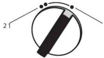
4. Settings

26_02_02_0783
1 Partial load
At low throughput 1/3 of the heating output is activated; at higher throughput 2/3 of the available heating output is enabled. This setting is suitable for hand washing at a basin, for example.
2 Full load
At a low throughput, 50% of the heating output is applied; at a higher throughput the full heating output is activated. This setting is suitable for washing dishes, for example.
» Click the output selector into the required position.
Recommended settings when using a thermostatic valve
» Set the output selector to full power.
4.1 Recommended tap/valve settings

Note
If the outlet temperature is not sufficiently high at full load and with the draw-off valve fully open, then more water is flowing through the appliance than can be heated by the heating system (appliance is at its output limit).
» Reduce the water volume at the draw-off valve.
Low draw-off rate = high outlet temperature
High draw-off rate = low outlet temperature
Twin lever tap
| Output stage Application range | |
| Partial load | Washbasin |
| Full load | Bath, shower, sink |
» Add cold water if the temperature is too high when the tap is fully open.
Mono lever mixer
| Output stage Application range | |
| Full load | All |
Turn the tap lever to the highest temperature.
Fully open the tap.
Increase the outlet temperature by closing the tap slowly.
» Reduce the outlet temperature by adding cold water or opening the tap further, if possible.
Following an interruption of the water supply

Material losses
Following an interruption of the water supply the appliance must be recommissioned by carrying out the following steps, in order to prevent the destruction of the bare wire heating system.
» Disconnect the appliance from the power supply by removing the fuses/tripping the MCBs.
Open the tap for one minute until the appliance and its upstream cold water inlet line are free of air.
» Switch the mains power back ON again.
5. Cleaning, care and maintenance
Never use abrasive or corrosive cleaning agents. A damp cloth is sufficient for cleaning the appliance.
» Check the taps regularly. Limescale deposits at the spouts can be removed using commercially available descaling agents.
6. Troubleshooting
| Problem Cause Remedy | ||
| The appliance will not start despite the DHW valve being fully open. | There is no power. Check the fuses/ MCBs in your fuse box/distribution panel. | |
| The flow rate is too low for switching on the heating output. The aerator in the tap or the shower head is scaled up or contaminated. | Clean and/or descale the aerator or shower head. | |
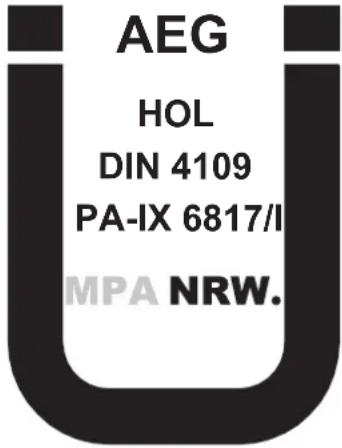
If you cannot remedy the fault, notify your qualified contractor. To facilitate and speed up your enquiry, please provide the serial number from the type plate (000000-0000-0000):
D0000041614
INSTALLATION
7. Safety
Only a qualified contractor should carry out installation, commissioning, maintenance and repair of the appliance.
7.1 General safety instructions
We guarantee trouble-free function and operational reliability only if original accessories and spare parts intended for the appliance are used.

Material losses
Observe the maximum inlet temperature. Higher temperatures may damage the appliance. You can limit the maximum inlet temperature by installing a central thermostatic valve.
7.2 Instructions, standards and regulations

Note
Observe all applicable national and regional regulations and instructions.
The protection rating IP 25 (hoseproof) can only be ensured with a correctly fitted cable grommet.
The specific electrical resistance of the water must not fall below that stated on the type plate. In a linked water network, observe the lowest electrical water resistance (see chapter "Specification / Application areas / Conversion table"). Your water supply utility will advise you of the specific electrical water resistance or conductivity.
8. Appliance description
8.1 Standard delivery
The following are delivered with the appliance:
- Wall mounting bracket
- Threaded stud for wall mounting
Installation template
2 twin connectors (cold water with shut-off valve)
Flat gaskets
Cable grommet (power cable from above / below) - Screws / rawl plugs for additional securing of the back panel when making water connections on finished walls
9. Preparations
9.1 Installation site

Material losses
Install the appliance in a room free from the risk of frost.
Always install the appliance vertically and near the draw-off point.
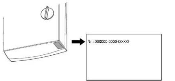
The appliance is suitable for undersink and oversink installations.
Undersink installation
26.02.021345
» Mount the appliance on the wall. The wall must have a sufficient load-bearing capacity.
9.2 Water installation
- Never operate with preheated water.
A safety valve is not required.
Safety valves are not permissible in the DHW pipe.
Flush the water line thoroughly.Ensure that the flow rate for switching on the appliance is achieved (see chapter "Specification / Data table", On). Increase the mains water pressure if the required flow rate is not achieved with the draw-off valve fully opened.
Taps/valves
Use appropriate pressure taps. Open taps are not permitted.
Thermostatic pressure valves must be suitable for hydraulically controlled instantaneous water heaters.

Note
Never use the shut-off valve in the cold water inlet to reduce the flow rate. It is intended for shutting off the appliance.
Permissible water pipe materials
Cold water inlet pipe:
Galvanised steel pipe, stainless steel pipe, copper pipe or plastic pipe
DHW outlet pipe:
Stainless steel pipe, copper pipe or plastic pipe

Material losses
If plastic pipework systems are used, take into account the maximum inlet temperature and the maximum pressure (see chapter "Specification / Data table").
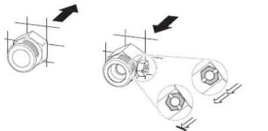
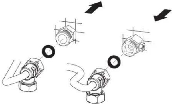
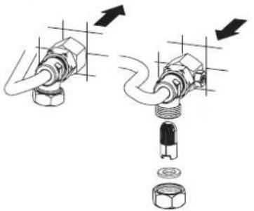
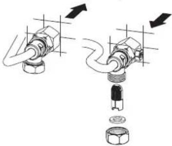
Flexible water connection lines
» If the appliance is installed with flexible water connection lines, ensure that the bayonet fittings of the pipe bends do not become twisted inside the appliance.
» Secure the back panel at the bottom with two additional screws.
10. Installation
10.1 Standard installation
Electrical connection from above; installation on unfinished walls
Water connection on unfinished walls
For further installation options, see chapter "Alternative installation options":
- Electrical connection from below on unfinished walls
- Electrical connection on finished walls
- Connecting a load shedding relay
Water installation on finished walls
Water connection on unfinished walls for appliance replacement
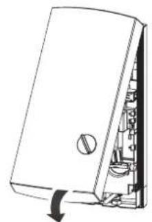
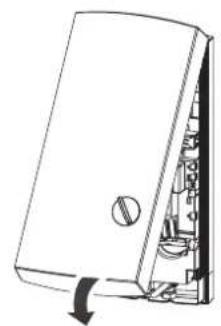
Opening the appliance
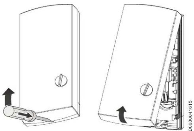
» Open the appliance by releasing the snap lock.
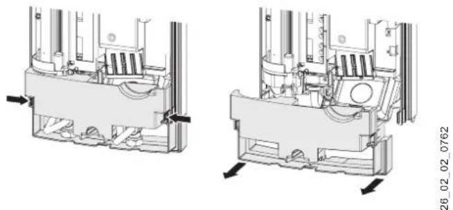
» Remove the back panel by pressing the two locking hooks and pulling the lower part of the back panel forwards.
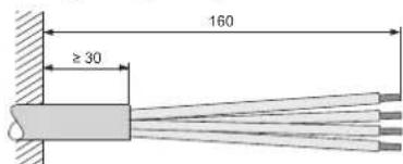
Preparing the power cable
26_02_02_0887
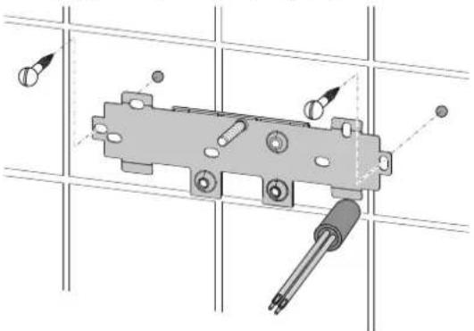
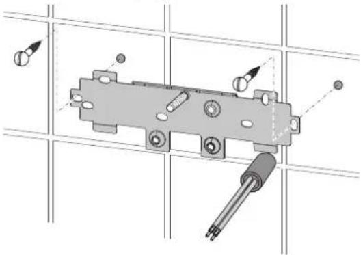
Fitting the wall mounting bracket
26_02_02_0972
» Mark out the holes for drilling with the installation template. If the appliance is to be installed with water connections on finished walls, also mark out the fixing holes in the lower part of the template.
Drill the holes and secure the wall mounting bracket with 2 screws and 2 rawl plugs (screws and rawl plugs are not part of the standard delivery).
» Fit the threaded stud provided.
» Mount the wall mounting bracket.
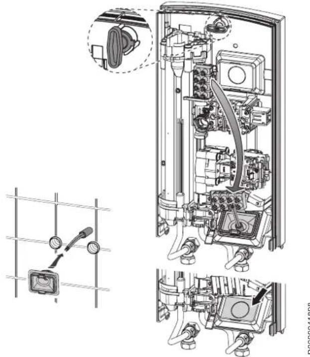
Fitting the cable grommet
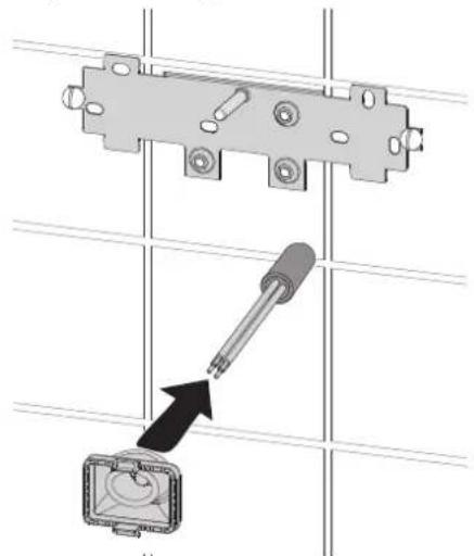
26_02_02_0950
» Fit the cable grommet. For connecting cables
>6mm2 , enlarge the hole in the cable grommet.
Making the water connection

Material losses
Carry out all water connection and installation work in accordance with regulations.
Seal and insert the twin connectors.

Material losses
Never use the shut-off valve in the cold water inlet to reduce the flow rate.
Preparing the back panel

Material losses
If you break out the wrong knock-out by mistake, you should use a new back panel.
Break out the cable grommet knock-out in the back panel. Deburr the sharp edges with a file if necessary.
Installing the appliance
0000041896
90
» Push the back panel over the threaded stud and the cable grommet. Pull the cable grommet by the locking hooks into the back panel using pliers, until both locking hooks audibly click into place.
Remove the transport plugs from the water connections.
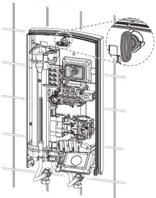
Press the back panel firmly into place and lock the fixing toggle by turning it clockwise through 90° .
D0000041925
» Screw the water connection pipes with flat gaskets on to the twin connectors.

Material losses
The strainer must be fitted for the appliance to function.
» When replacing an appliance, check whether the strainer is installed (see chapter "Maintenance").
Making the electrical connection

WARNING Electrocution
Carry out all electrical connection and installation work in accordance with relevant regulations.

WARNING Electrocution
The connection to the power supply must be in the form of a permanent connection in conjunction with the removable cable grommet. Ensure the appliance can be separated from the power supply by an isolator that disconnects all poles with at least 3mm contact separation.

WARNING Electrocution
Ensure that the appliance is earthed.

Material losses
Observe the type plate. The specified voltage must match the mains voltage.
» Connect the power cable to the mains terminal (see chapter "Specification / Wiring diagram").
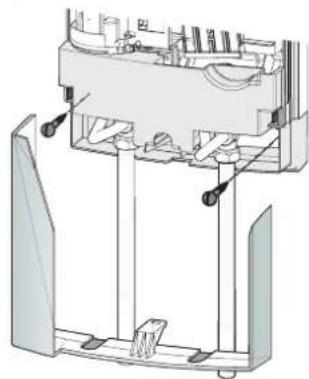
Fitting the lower back panel
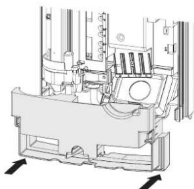
2602021348
Position the lower back panel onto the main back panel and click into place.
Align the mounted appliance by loosening the fixing toggle, aligning the power supply and back panel, and then re-tightening the fixing toggle. If the back panel is not flush with the wall, the appliance can be secured at the bottom with two additional screws.
10.2 Alternative installation options
10.2.1 Electrical connection from below on unfinished walls
» Fit the cable grommet.
Material losses If you break out the wrong knock-out by mistake, you should use a new back panel.
Break out the cable grommet knock-out in the back panel. Deburr the sharp edges with a file if necessary.
Reposition the mains terminal in the appliance from the top to the bottom.
Push the back panel over the threaded stud and the cable grommet. Pull the cable grommet by the locking hooks into the back panel using pliers, until both locking hooks audibly click into place.
Press the back panel firmly into place and lock the fixing toggle by turning it clockwise through 90° .
10.2.2 Electrical connection on finished walls
Note This type of connection changes the protection rating of the appliance.
Change the type plate. Cross out "IP 25" and mark the box "IP 24". Please use a ballpoint pen to do this.
Material losses If you break out the wrong knock-out by mistake, you should use a new back panel.
Cleanly cut or break out the required cable entries in the back panel (for positions, see chapter "Specification / Dimensions and connections"). Deburr the sharp edges with a file if necessary.
» Route the power cable through the cable grommet and connect it to the mains terminal.
10.2.3 Connecting a load shedding relay
Install a load shedding relay in the distribution board in conjunction with other electric appliances, e.g. electric storage heaters. The relay responds when the instantaneous water heater starts.
Material losses Connect the phase that switches the load shedding relay to the indicated terminal of the mains terminal in the appliance (see chapter "Specification / Wiring diagram").
10.2.4 Water installation on finished walls
Note This type of connection changes the protection rating of the appliance.
» Change the type plate. Cross out "IP 25" and mark the box "IP 24". Please use a ballpoint pen to do this.
26_02_02_0765
Fit water plugs with gaskets to seal the connection on unfinished walls.
» Fit a suitable pressure tap.
26_02_02_1006
Click the lower part of the back panel into place in the upper part of the back panel.
» Secure the connection pipes to the appliance.
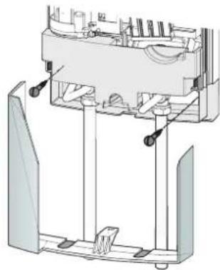
Secure the back panel at the bottom with two additional screws.
» Cleanly break out the knock-outs in the appliance cover. Deburr the sharp edges with a file if necessary.
Push the lower back panel under the connection pipes of the tap and click the lower back panel into place.
» Secure the connection pipes to the appliance.
10.3 Completing the installation
Open the shut-off valve in the twin connector or the cold water inlet line.
11. Commissioning

WARNING Electrocution Commissioning may only be carried out by a qualified contractor in accordance with safety regulations.
11.1 Initial start-up
D0000041620
Open and close all connected draw-off valves several times, until all air has been vented from the pipework and the appliance.
» Carry out a tightness check.
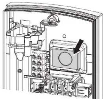
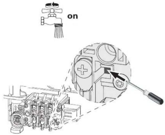
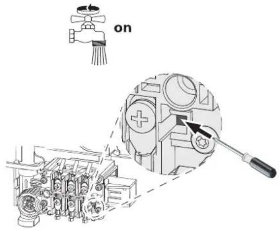
» Activate the safety pressure limiter by firmly pressing the reset button (the appliance is delivered with the safety pressure limiter deactivated).
Fit the appliance cover, ensuring it clicks into place. Check that the appliance cover is seated correctly.
Switch the mains power ON.
» Check the function of the appliance.
Appliance handover
» Explain the appliance function to users and familiarise them with its operation.
» Make users aware of potential dangers, especially the risk of scalding.
» Hand over these instructions.
11.2 Recommissioning
Vent the appliance and the cold water inlet line (see chapter "Settings").
See chapter "Commissioning / Initial start-up".
12. Shutting down the system
Isolate all poles of the appliance from the power supply.
Drain the appliance (see chapter "Maintenance").
13. Troubleshooting
| Fault Cause Remedy | ||
| The flow rate is too low. | The strainer in the appliance is dirty. | Clean the strainer. |
| Flow meter will not start despite tap being fully opened. | The start-up volume required to start up the heating output has not been reached. | Clean the strainer. |
| The appliance is not generating hot water despite audible sound of the differential pressure switch starting. | Safety pressure limiter (AP 3) has switched the appliance off for safety reasons. | Remove the cause of the fault (e.g. faulty pressure washer). |
| Protect the heating system against overheating by opening a draw-off valve downstream of the appliance for one minute. This depressurises and cools down the heating system. | ||
| Activate the safety pressure limiter at flow pressure by pressing the reset button (see chapter "Commissioning"). | ||
| The heating system is faulty. | Check the heating system resistor, and replace it if required. |
14. Maintenance

WARNING Electrocution Before any work on the appliance, disconnect all poles from the power supply.
Draining the appliance
The appliance can be drained for maintenance work.

WARNING Burns Hot water may escape when draining the appliance.
» Close the shut-off valve in the twin connector or the cold water inlet line.
» Open all draw-off valves.
» Undo the water connections on the appliance.
» If dismantled, store the appliance in a room free from the risk of frost, as water residues remaining inside the appliance can freeze and cause damage.
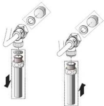
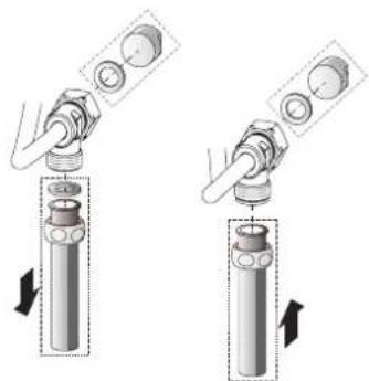
Cleaning the strainer
26_02_02_0949
If dirty, clean the strainer in the threaded cold water fitting. Close the shut-off valve in the cold water inlet line before removing, cleaning and refitting the strainer.
15. Specification

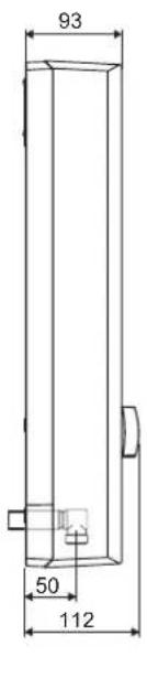
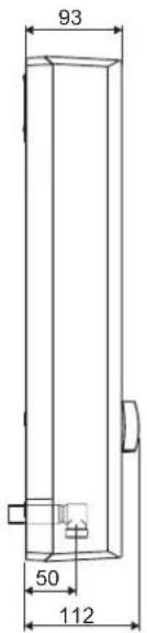
15.1 Dimensions and connections
D0000017757
| b02 Entry, electrical cables | | ||
| c01 Cold water inlet Male thread G 1/2 A | ||
| c06 DHW outlet | Male thread | G 1/2 A |

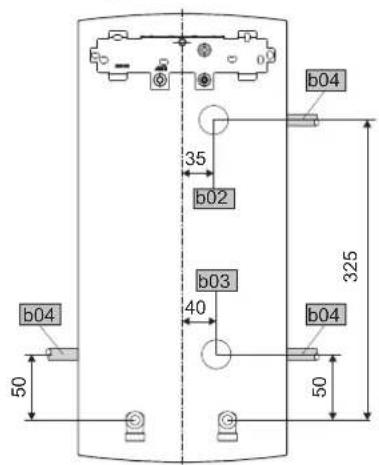
Alternative connection options
D0000019778
| b02 | Entry, electrical cables I |
| b03 | Entry, electrical cables II |
| b04 | Entry, electrical cables III |
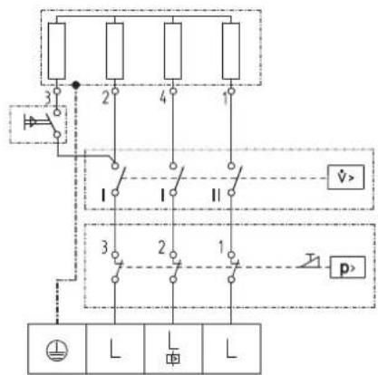
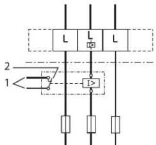
15.2 Wiring diagram
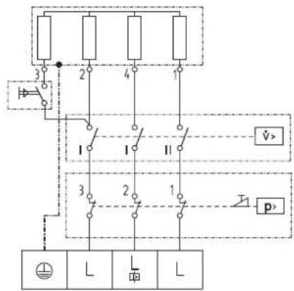
3/PE 400V
85_02_02_0002
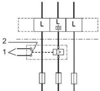
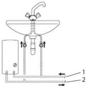
Priority control with LR 1-A
8502020003
1 Control cable to the contactor of the 2nd appliance (e.g. electric storage heater).
2 Control contact opens when switching the instantaneous water heater on.
15.3 DHW output
The DHW output is subject to the mains voltage, the appliance's connected load and the cold water inlet temperature. The rated voltage and rated output can be found on the type plate (see chapter "Troubleshooting").
| Connected load in kW 38 °C | DHW output in l/min. | |||
| Rated voltage Cold water inlet temperature | ||||
| 400 V | 5 °C | 10 °C | 15 °C | 20 °C |
| 13.5 | 5.8 | 6.9 | 8.4 | |
| 18.0 | 7.8 | 9.2 | 11.2 | |
| 21.0 | 9.1 | 10.7 | 13.0 | |
| 24.0 | 10.4 | 12.2 | 14.9 | |
| Connected load in kW | 50 °C DHW output in l/min. | ||||
| Rated voltage | Cold water inlet temperature | ||||
| 400 V | 5 °C 10 °C | 15 °C | 20 °C | ||
| 13.5 | 4.3 | 4.8 | 5.5 | 6.4 | |
| 18.0 | 5.7 | 6.4 | 7.3 | ||
| 21.0 | 6.7 | 7.5 | 8.6 | 10.0 | |
| 24.0 | 7.6 | 8.6 | 9.8 | ||
15.4 Application areas / conversion table
Specific electrical resistance and specific electrical conductivity (see chapter "Data table").
| Standard specifica- tion at 15 °C | 20 °C | 25 °C | ||||||
| Re-sist- ance ρ ≥ | Conductivity σ ≤ | Re-sist- ance ρ ≥ | Conductivity σ ≤ | Re-sist- ance ρ ≥ | Conductivity σ ≤ | |||
| Ωcm | mS/m | μS/cm | Ωcm | mS/m | μS/cm | Ωcm | mS/m | μS/cm |
| 900 | 111 | 1111 | 800 | 125 | 1250 | 735 | 136 | 1361 |
15.5 Pressure drop
Taps/valves
| Pressure drop at taps at flow rate of 10 l/min | ||
| Mono lever mixer tap, approx. | MPa | 0.04 - 0.08 |
| Thermostatic valve, approx. | MPa | 0.03 - 0.05 |
| Hand shower, approx. | MPa | 0.03 - 0.15 |
Sizing the pipework
When calculating the size of the pipework, a pressure drop for the appliance of 0.1MPa is recommended.
15.6 Fault conditions
In the event of faults, loads up to a maximum of 95°C at a pressure of 1.2 MPa can temporarily occur in the installation.
15.7 Details on energy consumption
The product data complies with EU regulations relating to the Directive on the ecological design of energy related products (ErP).
| DDLT PinControl 13 | DDLT PinControl 18 | DDLT PinControl 21 | DDLT PinControl 24 | ||
| 222384 | 222385 | 222386 | 222387 | ||
| Manufacturer | AEG Haustechnik | AEG Haustechnik | AEG Haustechnik | AEG Haustechnik | |
| Load profile | XS | S | S | S | |
| Energy efficiency class | A | A | A | A | |
| Annual power consumption | kWh | 469 | 483 | 483 | 483 |
| Energy conversion efficiency | % | 39 | 38 | 38 | 38 |
| Default temperature setting | °C | - | - | - | - |
| Sound power level | dB(A) | 15 | 15 | 15 | 15 |
| Special information on measuring efficiency | None | None | None | None |
15.8 Data table
| DDLT PinControl 13 DDLT PinControl 18 | DDLT PinControl 21 DDLT PinControl 24 | ||||
| 222384 222385 222386 222387 | |||||
| Electrical details | |||||
| Rated voltage V 400 400 400 400 | |||||
| Rated output 400 V stage I min. | kW | 4,6 | 6,3 | 7,4 | 8,3 |
| Rated output 400 V stage I max. | kW | 10,6 | 14,3 | 16,8 | 19,0 |
| Rated output 400 V stage II min. | kW | 6,8 | 9,2 | 10,8 | 12,2 |
| Rated output 400 V stage II max. | kW | 13,3 | 18,0 | 21,1 | 23,8 |
| Rated output | kW | 13,5 | 18 | 21 | 24 |
| Rated current | A | 19,5 | 26 | 31 | 35 |
| Fuses | A | 20 | 25 | 32 | 35 |
| Phases | 3/PE | 3/PE 3/PE 3/PE | |||
| Frequency | Hz | 50 | 50 | 50 | 50 |
| Specific resistance ρ15≥ (at θcold ≤25 °C) | Ω cm | 900 | 900 | 900 | 900 |
| Specific conductivity σ15≤ (at θcold ≤25 °C) | μS/cm | 1111 | 1111 | 1111 | 1111 |
| Versions | |||||
| IP-Rating | IP25 | IP25 | IP25 | IP25 | |
| Protection class | 1 | 1 | 1 | 1 | |
| Insulation block | Plastic | Plastic | Plastic | Plastic | |
| Heating system heat generator | Bare wire | Bare wire | Bare wire | Bare wire | |
| Connections | |||||
| Water connection | G 1/2 A | G 1/2 A | G 1/2 A | G 1/2 A | |
| Application limits | |||||
| Max. permissible pressure | MPa | 1 | 1 | 1 | 1 |
| Values | |||||
| Max. permissible inlet temperature | °C | 25 | 25 | 25 | 25 |
| ON stage I | l/min | 2,4 | 3,0 | 3,5 | 4,1 |
| ON stage II | l/min | 3,9 | 4,9 | 5,6 | 6,3 |
| Pressure drop at flow rate | MPa | 0,09 | 0,11 | 0,13 | 0,15 |
| Flow rate for pressure drop | l/min | 3,9 | 4,5 | 5,6 | 6,3 |
| Flow rate limit at | l/min | 4,7 | 5,9 | 7,0 | 7,8 |
| DHW delivery | l/min | 7,0 | 9,4 | 11,1 | 12,5 |
| Δθ at DHW delivery | K | 26 | 26 | 26 | 26 |
| Hydraulic data | |||||
| Rated capacity | I 0,4 0,4 0,4 0,4 | ||||
| Dimensions | |||||
| Height | mm | 485 | 485 | 485 | 485 |
| Width | mm | 226 226 226 226 | |||
| Depth | mm | 93 | 93 | 93 | 93 |
| Weights | |||||
| Weight | kg | 3,6 3,6 3,6 3,6 | |||
Guarantee
The guarantee conditions of our German companies do not apply to appliances acquired outside of Germany. In countries where our subsidiaries sell our products a guarantee can only be issued by those subsidiaries. Such guarantee is only granted if the subsidiary has issued its own terms of guarantee. No other guarantee will be granted.
We shall not provide any guarantee for appliances acquired in countries where we have no subsidiary to sell our products. This will not affect warranties issued by any importers.
Environment and recycling
We would ask you to help protect the environment. After use, dispose of the various materials in accordance with national regulations.
REMARQUESPARTICULIERES
UTILISATION
10.3 Montage aflsuiten
1.1.2 CmBOLbl, BnD onaCHOCTN
CMBOB BnOnaCHOCTN
|  | Травма |
|  | Порожения заektочescmium током |
|  | Ожог (ожог, обварUbанке) |
1.1.3 CmHaJIbHbIe cNoBa
》3TOT CUMBOI YKa3bIBaet Ha HeO6XoDMOCtB BbINONHeHnI ONpeJeHHbIX DeiCTBNI. OnuCAHne HeO6XoDMbIX DeiCTBNI npNBeJHO Wa 3a WaROM.
1.3 EinnuiznMepenH

yKa3aHne
Ecnn He yka3aHO Hoe, Bce pa3MepbI npBedeHb IMnI IInMeTpax.
2. TexHnka 6e30nacHOCTN
2.1 NcnoB3ObaHne no Ha3HaueHnIO
Pnp6op npedna3haen dny 6b10BOrO nCnOlb3oBaHn. Inerero 6e3oNaChoro 0cNyKuBaHn NOnb3oBaTeHne Tpe6yeTc npoxDntb uHCTpykTaK. Bo3moXHO nCnOlb3oBaHn np6opa He ToNbKO B 6bIty, Ho n, HapnPmep, Ha npEepnPaTnAX MaIoro 6n3heCa npu yCNOBn CO6JIOpHeHn Tex Xe ycNoBn EKcnNyataun.
Pp6op pa60taeT noD daBHeHem npeHa3Hauen Ha-rpeBa BOOpPoBOHOH Bobl. Pp6op MoKeT o6ecneuBaTb Ody Hn HeckObKO ToeK OT6opa.
IIO6oe INHOe INHHe Yka3aHHoe B HactoIeM pyKOBOCTBe IcNOb3OBAHne DaHHOr YoYCTPOIcTBA CHTAeTCa IcNOIb3OBAHNEM He No Ha3NaueHNI. IcNOIb3OBAHne No Ha3NaueHIO IOpa3yMeBaET co6JIOpDeHne Tpe6OBaHn HacToIeRpyKOBOCTBa, a TaKKe pyKOBOCTB K IcNOIb3YeMbIM npHaJdJIeXHOCTAM.
2.2 06uye yka3aHnno TeXnKe 6e3onacHOCTn

OCTOPOXHO oxor
Bo Bpempa60tbi apMaTypa MoKet HArpeBaTbCn Do TemnepaTypbI CbBiue 60°C
Pn TemnepaType B0nbHa BbIXoJe BblIe 43 ° C cyueCTByeOnacHocTb O6BapuBaHna.

IPEyIPEJKEHNE TpaBma
DeTAM CTAPWE 8 neT, a TAKKHe NnUaM cOrpaHueHHbIMN
fN3uuecknMM, ceHCOPHBIMN yMCTBeHHbIMN cNooc6
HOCTHM, He NMeIOUM ONbTA H He BnaDEIOUM INHOF
MaueNe O np6ope, pa3peEeHO McNOB3OBA Tb np6op
ToBko NOI npncMOPTpOM DpyrNX NnN NoCte COOT
BETCYBOUeO INCTpykTaKa O npabINax 6eONacCHO
NoB3OBAHNA I NOTeHuaMbHOI ONaCHOCTH Bcnyae
Heco6bIoEOHE3nx npabIN. He dOnyckTa WAnocTei
DeTe Cnp6obom. DeTN MOrY TBInONHbTb UcNTKY np6opa NTE BuNbI TeXHueCKTOO6cNyXMBAHNA, KOtOpBle
0bHuO pON3BOdA Tc NOnB3OBaTeJeM, ToBko NOI
npncMOPTpOM B3POCJIbIX.

MaterpnaIbIy uIep6
Pb30BATEnbDOnJKeH O6ecneuHTb 3auNTy BoOnpoBoDa n apMaTypbI OT 3aMep3AHn.
2.3 3HaK TexHnueckoro KOHTpOJa
Cm.3aBODckyTO Ta6nnyHa npu6ope.
| Еврашистор coOTBeTCTBVE | |
| EAC | Даннный пиробор coOTBeTCTByet Tpeбоваим Мбezоностоп тунческоу ретлamedда Таможениgo союза и пошел co- OTBeTCTbUOШи поочеву рiodтberгждени goOTBeTCTBIV. |
2.4 3HaK TexHnueckoro KOHTpOJa
Cm.3aObockyo Ta6nnyKa H np6ope.
TocydapCTBeHHbIe DOnyckn CBNTeTebCTBa:
Герм納
B COOTBETCTBUN CO CTPONTeJIbHbIMN HOPMaMn IN PpaBUNAMN BEOMCTBOM NO HA3Opy BbIaHO 06Uee CBNTeJIbCTBO O IOITBePJKDeHN BO3MOXHOCTN NcNOJIb3OBaHn INpNbopa c TOKN 3peHnERo UWMOBbIX XapakTepNCtNK.
3.Описане устpoиства
PpOToHbI BOoHaRpeBaTeBc rIpaBnueckm ynpaBHeHnem HArpeBaET BDOy, KOrda Ta npoxOHT Upe3 np6Op. PpiOTKpbTIN apMaTpybI nPpeBbIweHN pacxOda, Heo6XoDMORO DnB BKIOUeHn (CM. rnaBy "TexNueckne XapaKTePncTnK / Tabnua npaMeTpOB"), np6Op aBtOMaTnuEckn HaunHaet HarpeB. PacxOJ n TemnepaTyPy ropuey Bobl MoKHO perynnpoBaTc nomoBIO apMaTpybl.
Moxho Bb6paTb OIN H3 2 ypOBHe MoHocTn. KpOme TOro, npEycmOTpeHO rnpaBnueckoe ynpabneHne 2 ypOBHmMoHOCTN B 3aBcNMOCTn OT paCXoJa.
PerynpoBaHne pacxOda KOMnEHCnpyET KONE6aHn daBnEHHN, TEM cambm oecneuHBa npaKTnueckn HEn3MeHHyTeemepaTpy.PerynpoBaHne orpaHnUBAe paccOd, 6na-roDapra yemy BOOnpOBOJHa BOa BcERda HarpeBaetcdo DocTaTOHn TEMpeaTpbl.
HarpeBaTeJbHa nCTeMa
HarpeBaTeBHaCnCTema COTKpbTbIM HarpeBaTeBbIM 3eMeHOM 3aunueHa RepMeTNuHBIM nlaCTNKOBbIM KOpNycOM. HarpeBaTeBHa CnCTema pnproHa dIg MmKo N JecTKO BoDbI, TAK KA OHa IpaKTnueckn HeBOcPnMmNBa K O6pa30BaHIO HAKINH. HarpeBaTeBHa CnCTema ObecneuBaET 6bICTpoE nΦΦeKtNBHOe ChA6XKeHne ropaye BOOn.
4. Hactpoikn
26_02_02_0783
1 YactnuaHAR MoOHOCb
Pn Manom pacxode nCnoB3yETcra 1/3 MoHoctn Ha-rpeBa, npn 60nbem -2/3. 3Ta HacTpoKa NdoXoNT, Hanpnmep, nIa MbITb pyk.
2ПОннан MOUHOCb
Pn Manom pacxode BknoyaeTcnoOBHHaMoUHocThb HArpeBa, np60nbem - noHa MaOuHocTb.3TaHacTpouKa nOxDoxiHT, HApnpMep, nI MyBtBnOCybl.
3aФИКСИРУТЕ PERYЛТOP MOUHOCTN B HUXHOM NOLOXKeHIM.
PekomeHdaqna no HacptpoKe npnncnoIb30BaHH TepmoCTaTpyuOe apMaTpybl
YctaHaBnBaBaNtepepyTOpMOuHOCTN B NOJIOKeHNe NONHO MOUHOCTN.
4.1 Pekomehdaun no HacTpoJke JnapMaTypbl
yka3aHme
Ecnn pa3daTochb knp ropqey BoBbl nonHoctb0 OTkpbIt N yctaHOBnHa NOnHaa MOUHocTb HarpBa, HO pN 3Tom Boda Ha BblOde MMeet HeDcTaTOUHyo Temnepatpy,3to 3NaHT,4TOpe3 np6Op npoxoHT 6onbe BObl, qem MoKet Harpetb HarpeBaTeNbbl 3nemeHT (OCTnHyta npedEnbHa Ma OUsHocTb np6Opa).
B TaKOM cnUyae Heo6xOJMo cHn3ntb paCXoJ BODbl Ha pa3daTOOH MBeHTnE.
He6oBbOuPacXoD = BbICOKaTeMnepaTpaHa BbIXoJe
60nbwo paXoD =Hn3KaTeMnepaTpaHa BbIXOe
Apmatypac dBym pykamn
6. YctpaHHe HeNCnPaBHOCTeI
Pnp60mKHOyCTaHaBnBaTbNOpaKOBnHnHaHnHei
MOHTaK IOd paKOBuHOn
3 26.02.02.1345
Ecno own6ke 6bino bblomaho He to OTBepctne nJa Ka6ebhoB Btyn, Heo6xOIMO nCnOJIb3OBaTb HOByIO 3aDHIO CTeHky!
» Ha 3aDHe nCTeHKe npn6opa YnCTO BbInoJHnTb Heo6xoDnMbIe npoxoHbIe OTBepCTn (NX pacnoJooXeHne cm. rnaBy «Texnueckne XapaKtepncTkn / Pa3mepbl coeHNHeHn»).Pn HauuMn ocTpbx KpOMok INx Heo6xoDnMo YnCTO o6pa60TaTb HauNlbHnKOM.
PpOyCTnTb Ka6eNb 3JIeKTpOnnTaHnA uepe3 Ka6eNbHyIO BTVIky N IOkNIOuHTb erO K CoeINHnTeBHOJ KIeMMe CETN.
10.2.3 IopKnIoueHne pene c6poca Harpy3Kn
Pene c6poca Harpy3Kn B 3JneKTPopacnpedeHntbHom yctpoiCTBe CnEpyet NcNOB3OBaTb COBMecTHO C npyHMn 3JneKTPoPi6Opamn, HanpImep, c3JneKTPnuEcckmMn HaKoNtteHBblm BOHOHarpeBaTeIaMn. C6poc Harpy3Kn OcyuectBlaeTcpi np pa6ote npOTouHOro BOHOHarpeBaTeIa.

MATEPnabhbnyyueep6
Nopknnohtb a3y,Ha kotopyu yctaHOboNeho pene c6poca harpy3kn, K nomeeHHo coeHHntelbHOH klemme cetn B npn6ope (cm. rnaBy «TexHHueckne xa- paKtpncnKn /3neKTPnueeckne cxembln coeHHenHna»).
10.2.4 BODONPOBOHbIe pa6Otbl cnoco6OM OTKpbITOro MOHTaKa

Yka3aHne
Pn Takom cnoc6e noKIOueHn 3MeHITcA CTeneHb 3aunTb np6opa.
» NImeHtB dAHHbIe Ha 3aBoDcKo Ta6nUyKe.3aepKHyTb MapKnupOBky «IP 25» n OTMeHtB KpeCTNKOMЯeKy «IP 24».Пр nToM nCOnb3ObaTb wapNKoByIO pyuKy.
26_02_02_0765
» Ha Tpy6oNpOBoD CkpyITo rO MOHTaXa yCTaHOBnTb 3a- rnyuKc CynIOTHNTeRnM.
» BbINOHNtB MOHTaX COOTBeTCTByIOUeH HAnOpHO apMaTypbI.
26_02_02_1006
》HnxHHIO qactb 3aHeH naHEn yCTaHOBNTb NOB BepxHHIO qactb N 3aueKHyTb.
》CoeunHHTb Tpy6bic npn6opom.
3aKpeNTb 3aHIOU cTeHKy, 3aHNCpOBaB ee CHN3y DByM NOJHHTeHBHIM BHTAMN.
» AkkypaTHo BbIOMaTb npoxOhbIe OTBepCTnB KpbIuKe np6opAp. Pn HAnuHcN OctPbIX KpOMK INx Heo6xoJIMOn UcTo 06pa6oTaTb HAnJIbHInKOM.
YcTaHOBnTb HxHxIOu cAcTb 3aDHe N aHeN NO Tpy6bl apMaTypbI N 3aΦNkCupOBaTb E B 3aDHe NaHeN.
»CoeunHntbTrepy6bicnpn6bopom.
10.3 3aBepWeHne MOHTaxKa
OTKpbTb3anOpHbBEHTnB BBOHOM Hnnne nINB Tpy6oPBODe NOaun XOJOnHOI BObl.
11. BbO B éKcπnyatauio

PPEyIPEKJEHNE nopaxKeHne 3JIeKtpueckm TOKOM BBoD np6oBa B3KcIIpyaTauIO MoXeT OcyuEcTBJrTbCra TOIbKO CnEuaNtCTOM npu YcNOBUN CO6IIOHeH NpaBUN TexHKn 6eOtonachOCTn.
11.1 NepBbI BBOd B 3KcNpyatauio
D0000041620
》MHOROKpaTHOOTKpbIbA Tb 3aKpbIbTaB BCE NOdknIOueH HbIe pa3daTOUHbIe BENTIN IO Tex NOP, NOKA B BOOpOnPOBOHOcTn IN Pn6ope He OCTaHETCR BO3dyxa.
»BbINHHTb npOBepKy repMeTuHOCn.
》AKTNBnPoBaTb npEdoxpaHntBbIOrpaHnHTeB TaBHeHna, CnBHO HaxaB KhoNky C6pOca (Ha MoMeNT NoCTaBKn np6oopa fYHKunnpEdoxpaHntBHorO OrpaHnHTeJ DaBHeHna DeakTNBnPOBaHa).
YcTaHOBnTb KpbIuKy np6opa n 3aФNKCuPoBaTb Do cnblIMOro ueyka. PpOBepntb noLoXeHne KpbIuKn np6opa.
》PdTaB ceTeBoe HnpanjKeHne.
PpOBepuTb pa60Tu npu6opa.
Ipepa np6opa
»O6bAChNTb nonb3OBaTeIIO npnHcun pa6oTb npn6opa n O3HaKOMNTb erO c npaBUNAMN NCNOB3OBaHNpN6opa.
》Ka3aTb N0JIb3OBATeNIO Ha BO3MOXHbIE ONaCHOCTN,OC6eHHo Ha ONaCHOCTb 06BapnBaHn.
》IpepaTbDaHHoepyKOBoDCTBO.
11.2 NobToPbI BBOB B 3KcnnyaTaunIO
Ydannb BO3dyx n3 np6opa n Tpy6oPBOda noaun xonoHHOBbl (CM. rnaBy «HaCtpoKnu»).
Cm. rnaBv «NepBbI BBOD B 3KcNpyaTaunHO
12. BbIbOД n3 эКсплуataци
ПОЛНOCТБЮ OБЕСТОУТБ ПИБОР C pa3MbIKaHINEM BCEX KOHTAKTOB.
OnopoxnHt np6Op,cm. rnaBy "Texo6nykubHne".
13. YctpaHne HencnpabHocTei
| Heincpnbnoctb Prunca HcNcNo6bYCTpaHEnn | ||
| Очenvсblaбий NOTOK. 3a ЗграZNHeN сeTuATы ФильТВ рпсбор. | ОчSENTь сeTuATы ФильТP. | |
| PerfyIaTOp paxXoda He ВКлIoUaTeCЯ, HeCMOTр Ha To,ЧTo apMaTypa ПОЛHOCbTO OTKpbIta. | ОчSENTь сeTuATы ФиьТP. | |
| Из priБOPа, HeCmOTр Ha cblshIMbI mIseIyOc ВКlIoUeHЯ dIφΦepeH- цalbHOro pere daBle- нЯ, He teHcT ropYaH ВODa. | ПробханITьНьHь ОрразнITь Дав- ня (AP 3) otKlIoUH PRIbOP IN3 coobpaxe- нь 6ezonacHOCTN. | УстРаHь priChINH HeCNPaBHOCTN (Ha- пример, HeCNPaBHy СлNBHоJ Кан). |
| ОТКрБТВ BeHTINb OTбОра ropYeH BOdI Ha odHy MINHTу Ддя 3a- цITbI HArpeBaTeHbON СИСТЕМБ IOT PererPReBa. ЭТО ПОЗВОЛТСАТь Ha- гPy3Kу C HarpeBaTeH- HоH CStEмы И obecne- чIT ee oxlanJaDEHnE. | ||
| АктувирOBaTь prideo- хранITьНьMоранH- чeTь ДавLEHЯ pri- налчHy ГИрВANuYe- СКTORO DAbLHЯ, Ддя эТOTO сIeДуET hAXaTb КнОнky CBpoCa (СM. Главу «ПерБуВ ВВОДВ эКСплуATAZHI»). | ||
| HcNcPabHа HarpeBa- ТelbHа СИСТЕм. | ИзмeрИТь соportИВе- нe В HarpeBaTeHbON СИСТЕм, pri NeO6- XODIMOCTN 3aMeHITb СоportИВЕHиE. |
14. Texo6cnyxmbaHne

PPEyIIPEXEHHNE npaKeHne 3JIeKtpueckm TOKOM Pn IIO6bIX pa6oTAX Heo6xOdmo nIoHoe OTKIOUeHne np6opa oT cetn.
Onopokhenne np6opa
MoxHo CnMb Body n3 np6opapnnpoBeHn pa60 no TexHueckomy 6cnyKuBaHIO.

PPEyIPEKJEHNE oxor
PpN CInBe BOdy n3 np6opa MoKeT BbTeKaTb rOpya
BOda.
3aKpbTb 3aOpHbB BENTINB B DBOHOM HINPiNE NIN B Tpy6oNpOBoDE NOaH XOIOHOB BObl.
》OTKpbItB Bce pa3daToHbIe BEHTnII.
»OTcoeINHHTpTy6oBPOBOBoIIOaUHBOBbOT np60pa.
XpaHnTb DEMOHNTPOBaHHb I np6Op B otAnnBaEMOM NOMEeHN, NOCKOBky B np6Op BcERda HaxoJrTaOCTaTKI BObl, KOTOpBle MOryT 3aMep3Hyb I NOBpeHnTb erO.
OuNTKa cetuaTOro 0nltpa
26.02.02.0949
OuHCTNTb CeTAtbI φ NtBp Bpe36OBOM CoeINHeHm Tpy- 60npoBoda XOnoHNO BODbl.3aKpbItb 3aOpHbI BEHTnbl B Tpy60npoBOe IOnaun XOnoHNO BODbl, DEMOHnPOBaTb CeTAtbI φ NtBp,OuHCTNTb ERO N yCTaHOBntb CHOBA.
15. Texhnueckne xapaKTepeNtIKN

15.1 Pa3MepbI n coeMHHeHnA
D0000017757
| b02 | Вво ддя кабеля ленисторпатони I | ||
| c01 | Патубok подачхлобно Вовы | Hapyжна розьба | G 1/2 A |
| c06 | Патубok вьхда горочи Вовы | Hapyжна розьба | G 1/2 A |
BapnantbI nodklouyen
D0000019778
b02BboDJaKa6eNa3JeKtpoNTaHnI
b03 Bvod nla Ka6eI 3neKtponntaHnII
b04 BBOIДЯ Ka6eN3JIeKTPoPntaHnI I
15.2 3JIeKTpUccka cxema
3/PE 400 B
85_02_02_0002
PnpopntHa cxema c LR 1-A
85_02_02_0003_
1 LInnnaeyn ynpablenen K KOHTaKTopy 2-ro npnbopa (HapnPmep,3eKtpueckomy 6oJnepy).
2 YnpablaIOUIO KOHTaKT pa3MbkaeTc npu BkIOueHIN pTOOHO BOOHaIpeBaTeJI.
15.3 PpOu3BOaNTeJIbHocTb no rOpayeB BoDe
PpOn3BODnTeNbHOCbNo rOpRyHe BOe 3aBncnt OT HApnPaKHeN B Cetn, Notpe6bnEmoMoUHcOtn np6opa N TempeatpybXoNOdHO Bobl. CBeDeHnO HomHaJIbHom HApnPaKHeN N HOMHaJIbHOm MOUHcOtn Yka3aHbI Ha 3aBOJcKO Tabnue (cm. rAby «YCTpaHeHne HeNCnPabHocTe»).
15.6 Bo3MOxHbIe HEnCnPaBHOCTM
PnHHeCnpaBHOCTN B BOOONPOBOHOcntMe MoryT BO3HNKaTb KpaTKOBpeMeHHbIe MaKcMaJIbHbIe HaRpy3KN, COpOBoXdAeMbIe NOBbIeHEm TempeAtypbI do 95°C n daBHeHndo1,2MJa.
15.7 XapaKTePncTnKn 3HepronoTpe6JeHnA
XapakTePncTNKn H3dEINNA COOTBETCTBYOT npEnncaHnM DnpeKtNBb EC, ONpEeJnoUoEe Tpe6oBaHnK EKOaN3aHy 3Hepronotpe6laoue npOdykun (ErP).
Seinakanduri paigaldamine
2602020972
Urzhumskaya street 4,
building 2
129343 Moscow
Tel. 0495 7753889
Fax 04957753887
Switzerland
STIEBEL ELTRON AG
Industrie West
Gass 8
5242 Lupfig
Tel. 056 4640-500
Fax 0564640-501


- HYDRAULICALLY CONTROLLED INSTANTANEOUS WATER HEATER
- INSTALLATION
- WARRANTY
- ENVIRONMENT AND RECYCLING
- SPECIAL INFORMATION
- OPERATION
- GENERAL INFORMATION
- 1.1 SAFETY INSTRUCTIONS
- 1.1.1 STRUCTURE OF SAFETY INSTRUCTIONS
- 1.1.2 SYMBOLS, TYPE OF RISK
- 1.1.3 KEYWORDS
- 1.2 OTHER SYMBOLS IN THIS DOCUMENTATION
- 1.3 UNITS OF MEASUREMENT
- SAFETY
- 2.1 INTENDED USE
- 2.2 GENERAL SAFETY INSTRUCTIONS
- 2.3 TEST SYMBOLS
- APPLIANCE DESCRIPTION
- HEATING SYSTEM
- SETTINGS
- RECOMMENDED SETTINGS WHEN USING A THERMOSTATIC VALVE
- 4.1 RECOMMENDED TAP/VALVE SETTINGS
- NOTE
- TWIN LEVER TAP
- MONO LEVER MIXER
- FOLLOWING AN INTERRUPTION OF THE WATER SUPPLY
- MATERIAL LOSSES
- CLEANING, CARE AND MAINTENANCE
- TROUBLESHOOTING
- 7.1 GENERAL SAFETY INSTRUCTIONS
- 7.2 INSTRUCTIONS, STANDARDS AND REGULATIONS
- 8.1 STANDARD DELIVERY
- PREPARATIONS
- 9.1 INSTALLATION SITE
- 9.2 WATER INSTALLATION
- TAPS/VALVES
- PERMISSIBLE WATER PIPE MATERIALS
- FLEXIBLE WATER CONNECTION LINES
- 10.1 STANDARD INSTALLATION
- MAKING THE WATER CONNECTION
- PREPARING THE BACK PANEL
- INSTALLING THE APPLIANCE
- MAKING THE ELECTRICAL CONNECTION
- WARNING ELECTROCUTION
- FITTING THE LOWER BACK PANEL
- 10.2 ALTERNATIVE INSTALLATION OPTIONS
- 10.2.1 ELECTRICAL CONNECTION FROM BELOW ON UNFINISHED WALLS
- MATERIAL LOSSES IF YOU BREAK OUT THE WRONG KNOCK-OUT BY MISTAKE, YOU SHOULD USE A NEW BACK PANEL
- 10.2.2 ELECTRICAL CONNECTION ON FINISHED WALLS
- NOTE THIS TYPE OF CONNECTION CHANGES THE PROTECTION RATING OF THE APPLIANCE
- 10.2.3 CONNECTING A LOAD SHEDDING RELAY
- MATERIAL LOSSES CONNECT THE PHASE THAT SWITCHES THE LOAD SHEDDING RELAY TO THE INDICATED TERMINAL OF THE MAINS TERMINAL IN THE APPLIANCE (SEE CHAPTER "SPECIFICATION / WIRING DIAGRAM")
- 10.2.4 WATER INSTALLATION ON FINISHED WALLS
- 10.3 COMPLETING THE INSTALLATION
- COMMISSIONING
- 11.1 INITIAL START-UP
- APPLIANCE HANDOVER
- 11.2 RECOMMISSIONING
- SHUTTING DOWN THE SYSTEM
- MAINTENANCE
- DRAINING THE APPLIANCE
- SPECIFICATION
- 15.2 WIRING DIAGRAM
- 15.3 DHW OUTPUT
- 15.4 APPLICATION AREAS / CONVERSION TABLE
- 15.5 PRESSURE DROP
- SIZING THE PIPEWORK
- 15.6 FAULT CONDITIONS
- 15.7 DETAILS ON ENERGY CONSUMPTION
- GUARANTEE
- REMARQUESPARTICULIERES
- UTILISATION
- 10.3 MONTAGE AFLSUITEN
- 1.1.2 CMBOLBL, BND ONACHOCTN
- 1.1.3 CMHAJIBHBIE CNOBA
- 1.3 EINNUIZNMEPENH
- YKA3AHNE
- TEXHNKA 6E30NACHOCTN
- 2.1 NCNOB3OBAHNE NO HA3HAUEHNIO
- 2.2 06UYE YKA3AHNNO TEXNKE 6E3ONACHOCTN
- OCTOPOXHO OXOR
- IPEYIPEJKEHNE TPABMA
- MATERPNAIBIY UIEP6
- 2.3 3HAK TEXHNUECKORO KOHTPOJA
- 2.4 3HAK TEXHNUECKORO KOHTPOJA
- 3.ОПИСАНЕ УСТPOИСТВА
- HARPEBATEJBHA NCTEMA
- HACTPOIKN
- PEKOMEHDAQNA NO HACPTPOKE NPNNCNOIB30BAHH TEPMOCTATPYUOE APMATPYBL
- 4.1 PEKOMEHDAUN NO HACTPOJKE JNAPMATYPBL
- YKA3AHME
- YCTPAHHE HENCNPABHOCTEI
- MOHTAK IOD PAKOBUHON
- 10.2.3 IOPKNIOUEHNE PENE C6POCA HARPY3KN
- MATEPNABHBNYYUEEP6
- 10.2.4 BODONPOBOHBIE PA6OTBL CNOCO6OM OTKPBITORO MOHTAKA
- 10.3 3ABEPWEHNE MOHTAXKA
- BBO B ÉKCΠNYATAUIO
- 11.1 NEPBBI BBOD B 3KCNPYATAUIO
- IPEPA NP6OPA
- 11.2 NOBTOPBI BBOB B 3KCNNYATAUNIO
- BBIBOД N3 ЭКСПЛУATAЦИ
- YCTPAHNE HENCNPABHOCTEI
- TEXO6CNYXMBAHNE
- ONOPOKHENNE NP6OPA
- TEXHNUECKNE XAPAKTEPENTIKN
- 15.2 3JIEKTPUCCKA CXEMA
- 15.3 PPOU3BOANTEJIBHOCTB NO ROPAYEB BODE
- 15.6 BO3MOXHBIE HENCNPABHOCTM
- 15.7 XAPAKTEPNCTNKN 3HEPRONOTPE6JEHNA
- SWITZERLAND
Brand : AEG
Model : DDLT PinControl 21
Category : Heating