
DDLT PinControl 18 - Heating AEG - Free user manual and instructions
Find the device manual for free DDLT PinControl 18 AEG in PDF.
| Product type | Hydraulically controlled instantaneous water heater |
| Brand | AEG |
| Model | DDLT PinControl 18 |
| Nominal power | 18 kW |
| Power supply | 400 V three-phase (3/PE), 50 Hz, 26 A |
| Dimensions (H x W x D) | 485 x 226 x 93 mm |
| Weight | 3.6 kg |
| Protection rating | IP 25 (protected against water jets) |
| Protection class | 1 |
| Heating system | Bare wire in synthetic sheath |
| Hydraulic connection | G 1/2 A (male thread) |
| Maximum admissible pressure | 1 MPa (10 bar) |
| Maximum inlet temperature | 25 °C |
| Switching flow rate (setting II) | 4.9 l/min |
| Limited maximum flow rate | 5.9 l/min |
| Minimum specific resistivity (at 15°C) | 900 Ω·cm |
| Hot water capacity (38 °C, 10°C inlet) | 9.2 l/min |
| Power selector | 2 levels (Partial power and Full power) |
| Safety functions | Safety pressure switch, temperature limiter |
| Cleaning and maintenance | Damp cloth, regular descaling of taps, cleaning the filter |
| Installation | Wall-mounted, vertical, frost-free |
| Warranty | According to local subsidiary conditions |
| Energy efficiency class | A |
Frequently Asked Questions - DDLT PinControl 18 AEG
User questions about DDLT PinControl 18 AEG
0 question about this device. Answer the ones you know or ask your own.
Ask a new question about this device
Download the instructions for your Heating in PDF format for free! Find your manual DDLT PinControl 18 - AEG and take your electronic device back in hand. On this page are published all the documents necessary for the use of your device. DDLT PinControl 18 by AEG.
USER MANUAL DDLT PinControl 18 AEG
Hydraulically controlled instantaneous water heater
Operation and Installation 16
natural_image
Simple diagram of a circular object with a vertical bar and two dots, no text or symbols present.26 02 02 0783
1 Teilleistung
26_02_02_1345
26_02_02_1344
natural_image
Technical line drawing of a door panel with internal components and directional arrows indicating movement (no text or symbols)natural_image
Technical line drawing of a mechanical assembly with two views (top and side), showing internal components and directional arrows (no text or symbols)natural_image
Technical diagram of a mechanical assembly with mounting holes and a rod, shown without any text or symbols.natural_image
Mechanical diagram showing two configurations of a pulley system with arrows indicating motion direction (no text or labels)26_02_02_0948
natural_image
Technical line drawing of an industrial machine interior with no visible text or symbolsD0000041896
natural_image
Technical line drawing of an internal electrical enclosure with internal components and a close-up inset showing a device (no text or symbols present)D0000041897
natural_image
Diagram showing three mechanical components connected by a pipe, with arrows indicating motion direction (no text or symbols)D0000041925
natural_image
Technical line drawing of a mechanical assembly with no visible text or symbols26_02_02_1348
natural_image
Technical line drawing of a mechanical device interior with exploded view and component details (no text or symbols)natural_image
Two-step diagram showing a mechanical assembly with cylindrical components and adjustment arrows (no text or symbols)26_02_02_0765
natural_image
Technical diagram of a mechanical assembly with no visible text or symbols26_02_02_1006
natural_image
Diagram of a device with internal components and a directional arrow indicating rotation (no text or symbols)
D0000041620
natural_image
Diagram showing two mechanical components with arrows indicating motion, no text or symbols present26_02_02_0949
85_02_02_0003_
- General information .... 17
- Safety 17
- Appliance description....18
- Settings....18
- Cleaning, care and maintenance 19
- Troubleshooting 19
INSTALLATION
- Safety 20
- Appliance description....20
- Preparations....20
- Installation....21
- Commissioning....24
- Shutting down the system....24
- Troubleshooting 24
- Maintenance....25
- Specification 25
WARRANTY
ENVIRONMENT AND RECYCLING
SPECIAL INFORMATION
• The appliance may be used by children aged 8 and up and persons with reduced physical, sensory or mental capabilities or a lack of experience and know-how, provided that they are supervised or they have been instructed on how to use the appliance safely and have understood the resulting risks. Children must never play with the appliance. Children must never clean the appliance or perform user maintenance unless they are supervised.
- Risk of scalding: The tap can reach temperatures in excess of 60 °C.
- Ensure the appliance can be separated from the power supply by an isolator that disconnects all poles with at least 3 mm contact separation.
- Secure the appliance as described in chapter "Installation / Installation".
- Observe the maximum permissible pressure (see chapter "Specification / Data table").
- Drain the appliance as described in chapter "Installation / Maintenance / Draining the appliance".
OPERATION
1. General information
The chapters "Special Information" and "Operation" are intended for both the user and qualified contractors.
The chapter "Installation" is intended for qualified contractors.

Note
Read these instructions carefully before using the appliance and retain them for future reference.
Pass on the instructions to a new user if required.
1.1 Safety instructions
1.1.1 Structure of safety instructions

KEYWORD Type of risk
Here, possible consequences are listed that may result from failure to observe the safety instructions.
» Steps to prevent the risk are listed.
1.1.2 Symbols, type of risk
| Symbol Type of risk | |
 | Injury |
 | Electrocution |
 | Burns(burns, scalding) |
1.1.3 Keywords
| KEYWORD | Meaning |
| DANGER | Failure to observe this information will result in serious injury or death. |
| WARNING | Failure to observe this information may result in serious injury or death. |
| CAUTION | Failure to observe this information may result in non-serious or minor injury. |
1.2 Other symbols in this documentation

Note
General information is identified by the symbol shown on the left.
» Read these texts carefully.
| Symbol Meaning | |
| Material losses(appliance damage, consequential losses and environmental pollution) | |
| Appliance disposal | |
» This symbol indicates that you have to do something. The action you need to take is described step by step.
1.3 Units of measurement

Note
All measurements are given in mm unless stated otherwise.
2. Safety
2.1 Intended use
This appliance is intended for domestic use. It can be used safely by untrained persons. The appliance can also be used in a non-domestic environment, e.g. in a small business, as long as it is used in the same way.
This pressure appliance is designed to heat DHW. The appliance can supply one or more draw-off points.
Any other use beyond that described shall be deemed inappropriate. Observation of these instructions and of instructions for any accessories used is also part of the correct use of this appliance.
2.2 General safety instructions

CAUTION Burns
During operation, the tap can reach temperatures in excess of 60 °C.
There is a risk of scalding at outlet temperatures in excess of 43 °C.

WARNING Injury
The appliance may be used by children aged 8 and up and persons with reduced physical, sensory or mental capabilities or a lack of experience and know-how, provided that they are supervised or they have been instructed on how to use the appliance safely and have understood the resulting risks. Children must never play with the appliance. Children must never clean the appliance or perform user maintenance unless they are supervised.

Material losses
Protect the appliance and its tap against frost.
2.3 Test symbols
See type plate on the appliance.
Country-specific approvals and certifications:
Germany
A general test certificate as verification of suitability regarding noise emissions has been issued for this appliance, based on the State Building Regulations [Germany].
3. Appliance description
The hydraulically controlled instantaneous water heater heats water as it flows through the appliance. When a tap is opened, the heating output starts automatically as soon as the start-up volume is exceeded (see chapter "Specification / Data table"). The water volume and temperature can be adjusted at the tap.
You can choose between 2 output stages. In addition, 2 output stages are hydraulically controlled in relation to the flow rate.
The flow rate controller compensates for pressure fluctuations, thereby ensuring largely stable temperatures. The controller limits the throughput, thereby ensuring an adequate increase in the DHW temperature at all times.
Heating system
The bare wire heating system has a pressure-tested plastic casing. The heating system is suitable for hard and soft water areas and is largely insusceptible to scale build-up. This system ensures rapid and efficient DHW availability.
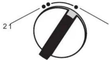
4. Settings
natural_image
Simple diagram of a circular object with a black bar and two dots, no text or symbols present.26_02_02_0783
1 Partial load
At low throughput 1/3 of the heating output is activated; at higher throughput 2/3 of the available heating output is enabled. This setting is suitable for hand washing at a basin, for example.
2 Full load
At a low throughput, 50 % of the heating output is applied; at a higher throughput the full heating output is activated. This setting is suitable for washing dishes, for example.
» Click the output selector into the required position.
Recommended settings when using a thermostatic valve
» Set the output selector to full power.
4.1 Recommended tap/valve settings

Note
If the outlet temperature is not sufficiently high at full load and with the draw-off valve fully open, then more water is flowing through the appliance than can be heated by the heating system (appliance is at its output limit).
» Reduce the water volume at the draw-off valve.
Low draw-off rate = high outlet temperature
High draw-off rate = low outlet temperature
Twin lever tap
| Output stage Application range | |
| Partial load | Washbasin |
| Full load | Bath, shower, sink |
» Add cold water if the temperature is too high when the tap is fully open.
Mono lever mixer
| Output stage Application range | |
| Full load | All |
» Turn the tap lever to the highest temperature.
» Fully open the tap.
» Increase the outlet temperature by closing the tap slowly.
» Reduce the outlet temperature by adding cold water or opening the tap further, if possible.
Following an interruption of the water supply

Material losses
Following an interruption of the water supply the appliance must be recommissioned by carrying out the following steps, in order to prevent the destruction of the bare wire heating system.
» Disconnect the appliance from the power supply by removing the fuses/tripping the MCBs.
» Open the tap for one minute until the appliance and its upstream cold water inlet line are free of air.
» Switch the mains power back ON again.
5. Cleaning, care and maintenance
» Never use abrasive or corrosive cleaning agents. A damp cloth is sufficient for cleaning the appliance.
» Check the taps regularly. Limescale deposits at the spouts can be removed using commercially available descaling agents.
6. Troubleshooting
| Problem Cause Remedy | ||
| The appliance will not start despite the DHW valve being fully open. | There is no power. Check the fuses/MCBs in your fuse box/distribution panel. | |
| The flow rate is too low for switching on the heating output.The aerator in the tap or the shower head is scaled up or contaminated. | Clean and/or descale the aerator or shower head. | |
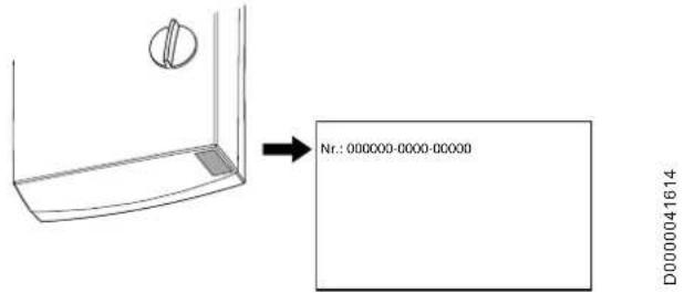
If you cannot remedy the fault, notify your qualified contractor. To facilitate and speed up your enquiry, please provide the serial number from the type plate (000000-0000-00000):
INSTALLATION
7. Safety
Only a qualified contractor should carry out installation, commissioning, maintenance and repair of the appliance.
7.1 General safety instructions
We guarantee trouble-free function and operational reliability only if original accessories and spare parts intended for the appliance are used.

Material losses
Observe the maximum inlet temperature. Higher temperatures may damage the appliance. You can limit the maximum inlet temperature by installing a central thermostatic valve.
72 Instructions, standards and regulations

Note
Observe all applicable national and regional regulations and instructions.
• The protection rating IP 25 (hoseproof) can only be ensured with a correctly fitted cable grommet.
• The specific electrical resistance of the water must not fall below that stated on the type plate. In a linked water network, observe the lowest electrical water resistance (see chapter "Specification / Application areas / Conversion table"). Your water supply utility will advise you of the specific electrical water resistance or conductivity.
8. Appliance description
8.1 Standard delivery
The following are delivered with the appliance:
- Wall mounting bracket
- Threaded stud for wall mounting
- Installation template
- 2 twin connectors (cold water with shut-off valve)
- Flat gaskets
- Cable grommet (power cable from above / below)
- Screws / rawl plugs for additional securing of the back panel when making water connections on finished walls
9. Preparations
9.1 Installation site

Material losses
Install the appliance in a room free from the risk of frost.
» Always install the appliance vertically and near the draw-off point.
The appliance is suitable for undersink and oversink installations.
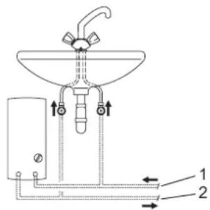
Undersink installation
26_02_02_1345
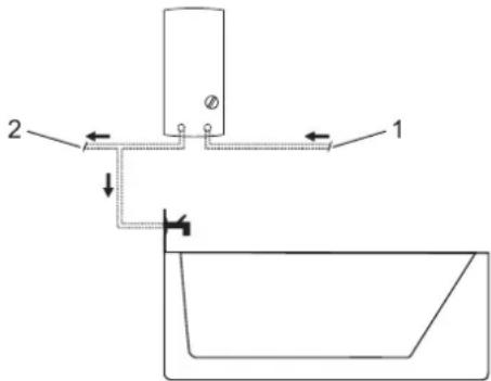
Oversink installation
26_02_02_1344
» Mount the appliance on the wall. The wall must have a sufficient load-bearing capacity.
9.2 Water installation
- Never operate with preheated water.
- A safety valve is not required.
- Safety valves are not permissible in the DHW pipe.
» Flush the water line thoroughly.
» Ensure that the flow rate for switching on the appliance is achieved (see chapter "Specification / Data table", On). Increase the mains water pressure if the required flow rate is not achieved with the draw-off valve fully opened.
Taps/valves
Use appropriate pressure taps. Open taps are not permitted.
Thermostatic pressure valves must be suitable for hydraulically controlled instantaneous water heaters.

Note
Never use the shut-off valve in the cold water inlet to reduce the flow rate. It is intended for shutting off the appliance.
Permissible water pipe materials
- Cold water inlet pipe:
Galvanised steel pipe, stainless steel pipe, copper pipe or plastic pipe - DHW outlet pipe:
Stainless steel pipe, copper pipe or plastic pipe

Material losses
If plastic pipework systems are used, take into account the maximum inlet temperature and the maximum pressure (see chapter "Specification / Data table").
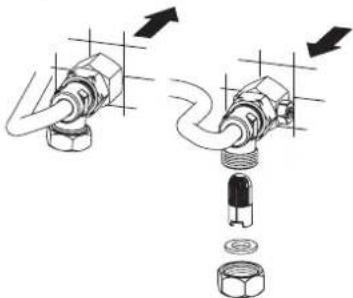
Flexible water connection lines
» If the appliance is installed with flexible water connection lines, ensure that the bayonet fittings of the pipe bends do not become twisted inside the appliance.
» Secure the back panel at the bottom with two additional screws.
10. Installation
10.1 Standard installation
- Electrical connection from above; installation on unfinished walls
• Water connection on unfinished walls
For further installation options, see chapter "Alternative installation options":
- Electrical connection from below on unfinished walls
• Electrical connection on finished walls - Connecting a load shedding relay
• Water installation on finished walls
• Water connection on unfinished walls for appliance replacement
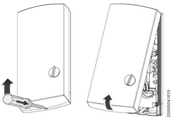
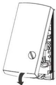
Opening the appliance
natural_image
Technical line drawing of a door switch mechanism showing two views: one with a valve and arrow indicator, the other with internal components and arrows indicating rotation (no text or symbols)» Open the appliance by releasing the snap lock.
natural_image
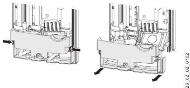
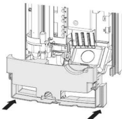
Technical line drawing of a mechanical assembly with two views (top and side), showing internal components and directional arrows (no text or symbols)» Remove the back panel by pressing the two locking hooks and pulling the lower part of the back panel forwards.
Preparing the power cable
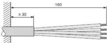
26_02_02_0887
Fitting the wall mounting bracket
natural_image
Technical diagram of a mechanical assembly with mounting holes and a tool, no visible text or symbols26_02_02_0972
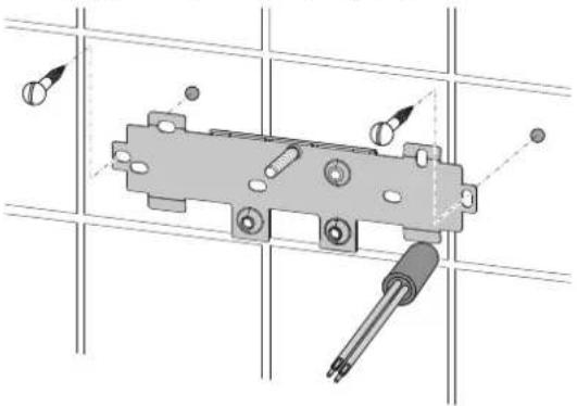
» Mark out the holes for drilling with the installation template. If the appliance is to be installed with water connections on finished walls, also mark out the fixing holes in the lower part of the template.
» Drill the holes and secure the wall mounting bracket with 2 screws and 2 rawl plugs (screws and rawl plugs are not part of the standard delivery).
» Fit the threaded stud provided.
» Mount the wall mounting bracket.
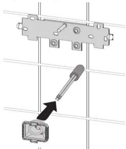
Fitting the cable grommet
natural_image
Technical diagram showing a mechanical bracket and a close-up of a component with an arrow indicating direction (no text or symbols present)26_02_02_0950
» Fit the cable grommet. For connecting cables
6 mm², enlarge the hole in the cable grommet.
Making the water connection
Material losses Carry out all water connection and installation work in accordance with regulations.
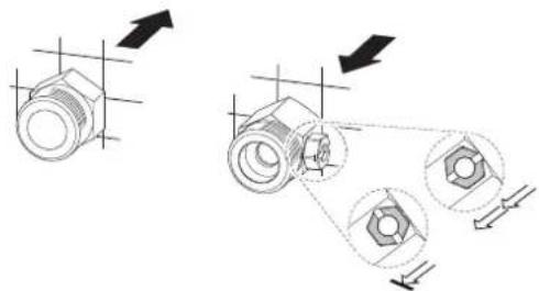
natural_image
Technical diagram showing two mechanical assembly states with arrows indicating direction (no text or symbols)26_02_02_0948
» Seal and insert the twin connectors.
Material losses Never use the shut-off valve in the cold water inlet to reduce the flow rate.
Preparing the back panel
Material losses If you break out the wrong knock-out by mistake, you should use a new back panel.
natural_image
Technical line drawing of an industrial machine with control panel and piping (no text or symbols)D0000041896
» Break out the cable grommet knock-out in the back panel. Deburr the sharp edges with a file if necessary.
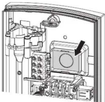
Installing the appliance
natural_image
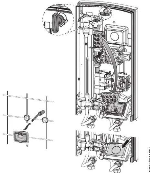
Technical line drawing of an internal electrical enclosure with internal components and a close-up inset showing a device (no text or symbols present)D0000041897
» Push the back panel over the threaded stud and the cable grommet. Pull the cable grommet by the locking hooks into the back panel using pliers, until both locking hooks audibly click into place.
» Remove the transport plugs from the water connections.
» Press the back panel firmly into place and lock the fixing toggle by turning it clockwise through 90°.
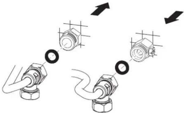
natural_image
Diagram showing three mechanical components connected by a pipe, with arrows indicating motion direction (no text or symbols)D0000041925
» Screw the water connection pipes with flat gaskets on to the twin connectors.
Material losses The strainer must be fitted for the appliance to function.
» When replacing an appliance, check whether the strainer is installed (see chapter "Maintenance").
Making the electrical connection
WARNING Electrocution Carry out all electrical connection and installation work in accordance with relevant regulations.
WARNING Electrocution The connection to the power supply must be in the form of a permanent connection in conjunction with the removable cable grommet. Ensure the appliance can be separated from the power supply by an isolator that disconnects all poles with at least 3 mm contact separation.
WARNING Electrocution Ensure that the appliance is earthed.
Material losses Observe the type plate. The specified voltage must match the mains voltage.
» Connect the power cable to the mains terminal (see chapter "Specification / Wiring diagram").
Fitting the lower back panel
natural_image
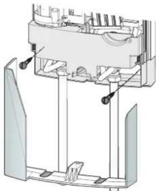
Technical line drawing of a mechanical assembly with no visible text or symbols26 02 02 1348
» Position the lower back panel onto the main back panel and click into place.
» Align the mounted appliance by loosening the fixing toggle, aligning the power supply and back panel, and then re-tightening the fixing toggle. If the back panel is not flush with the wall, the appliance can be secured at the bottom with two additional screws.
10.2 Alternative installation options
10.2.1 Electrical connection from below on unfinished walls
natural_image
Technical diagram of a mechanical device interior with exploded view and schematic views (no text or labels)» Fit the cable grommet.

Material losses If you break out the wrong knock-out by mistake, you should use a new back panel.
» Break out the cable grommet knock-out in the back panel. Deburr the sharp edges with a file if necessary.
» Reposition the mains terminal in the appliance from the top to the bottom.
» Push the back panel over the threaded stud and the cable grommet. Pull the cable grommet by the locking hooks into the back panel using pliers, until both locking hooks audibly click into place.
» Press the back panel firmly into place and lock the fixing toggle by turning it clockwise through 90°.
10.2.2 Electrical connection on finished walls

Note
This type of connection changes the protection rating of the appliance.
» Change the type plate. Cross out "IP 25" and mark the box "IP 24". Please use a ballpoint pen to do this.

Material losses
If you break out the wrong knock-out by mistake, you should use a new back panel.
» Cleanly cut or break out the required cable entries in the back panel (for positions, see chapter "Specification / Dimensions and connections"). Deburr the sharp edges with a file if necessary.
» Route the power cable through the cable grommet and connect it to the mains terminal.
10.2.3 Connecting a load shedding relay
Install a load shedding relay in the distribution board in conjunction with other electric appliances, e.g. electric storage heaters. The relay responds when the instantaneous water heater starts.

Material losses
Connect the phase that switches the load shedding relay to the indicated terminal of the mains terminal in the appliance (see chapter "Specification / Wiring diagram").
10.2.4 Water installation on finished walls

Note
This type of connection changes the protection rating of the appliance.
» Change the type plate. Cross out "IP 25" and mark the box "IP 24". Please use a ballpoint pen to do this.
natural_image
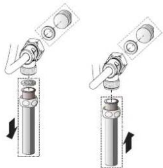
Two-step diagram showing a mechanical assembly with a cylindrical component being inserted, no text or symbols present.26_02_02_0765
» Fit water plugs with gaskets to seal the connection on unfinished walls.
» Fit a suitable pressure tap.
natural_image
Technical diagram of a mechanical assembly with no visible text or symbols26_02_02_1006
» Click the lower part of the back panel into place in the upper part of the back panel.
» Secure the connection pipes to the appliance.
» Secure the back panel at the bottom with two additional screws.
» Cleanly break out the knock-outs in the appliance cover. Deburr the sharp edges with a file if necessary.
» Push the lower back panel under the connection pipes of the tap and click the lower back panel into place.
» Secure the connection pipes to the appliance.
10.3 Completing the installation
» Open the shut-off valve in the twin connector or the cold water inlet line.
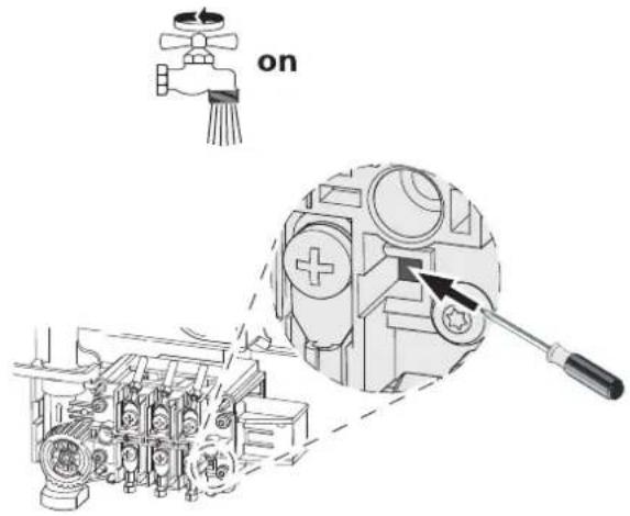
11. Commissioning

WARNING Electrocution Commissioning may only be carried out by a qualified contractor in accordance with safety regulations.
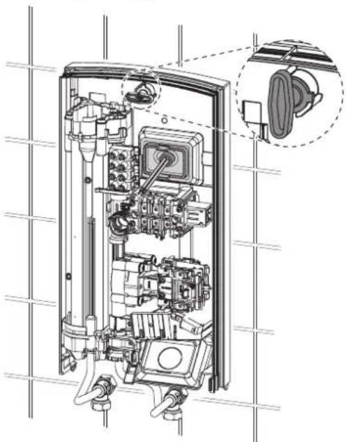
11.1 Initial start-up
natural_image
Diagram of a device with internal components and a directional arrow indicating rotation (no text or symbols)
D0000041620
» Open and close all connected draw-off valves several times, until all air has been vented from the pipe-work and the appliance.
» Carry out a tightness check.
» Activate the safety pressure limiter by firmly pressing the reset button (the appliance is delivered with the safety pressure limiter deactivated).
» Fit the appliance cover, ensuring it clicks into place. Check that the appliance cover is seated correctly.
» Switch the mains power ON.
» Check the function of the appliance.
Appliance handover
» Explain the appliance function to users and familiarise them with its operation.
» Make users aware of potential dangers, especially the risk of scalding.
» Hand over these instructions.
11.2 Recommissioning
Vent the appliance and the cold water inlet line (see chapter "Settings").
See chapter "Commissioning / Initial start-up".
12. Shutting down the system
» Isolate all poles of the appliance from the power supply.
» Drain the appliance (see chapter "Maintenance").
- Troubleshooting
| Fault Cause Remedy | ||
| The flow rate is too low. | The strainer in the appliance is dirty. | Clean the strainer. |
| Flow meter will not start despite tap being fully opened. | The start-up volume required to start up the heating output has not been reached. | Clean the strainer. |
| The appliance is not generating hot water despite audible sound of the differential pressure switch starting. | Safety pressure limiter (AP 3) has switched the appliance off for safety reasons. | Remove the cause of the fault (e.g. faulty pressure washer). |
| Protect the heating system against over-heating by opening a draw-off valve downstream of the appliance for one minute. This depressurises and cools down the heating system. | ||
| Activate the safety pressure limiter at flow pressure by pressing the reset button (see chapter "Commissioning"). | ||
| The heating system is faulty. | Check the heating system resistor, and replace it if required. |
14. Maintenance

WARNING Electrocution Before any work on the appliance, disconnect all poles from the power supply.
Draining the appliance
The appliance can be drained for maintenance work.

WARNING Burns Hot water may escape when draining the appliance.
» Close the shut-off valve in the twin connector or the cold water inlet line.
» Open all draw-off valves.
» Undo the water connections on the appliance.
» If dismantled, store the appliance in a room free from the risk of frost, as water residues remaining inside the appliance can freeze and cause damage.
Cleaning the strainer
26_02_02_0949
If dirty, clean the strainer in the threaded cold water fitting. Close the shut-off valve in the cold water inlet line before removing, cleaning and refitting the strainer.
15. Specification
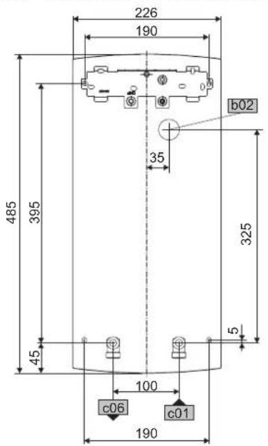
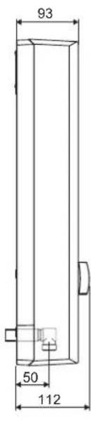
15.1 Dimensions and connections
D0000017757
| b02 Entry, electrical cables I | ||
| c01 Cold water inlet Male thread G 1/2 A | ||
| c06 DHW outlet | Male thread | G 1/2 A |
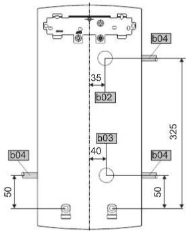
Alternative connection options
D0000019778
| b02 | Entry, electrical cables I |
| b03 | Entry, electrical cables II |
| b04 | Entry, electrical cables III |
15.2 Wiring diagram
3/PE \~ 400 V
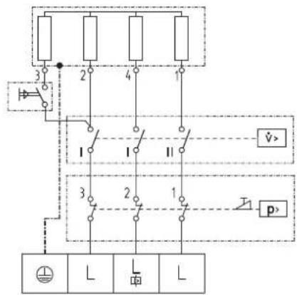
85_02_02_0002
Priority control with LR 1-A
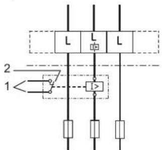
85_02_02_0003_
1 Control cable to the contactor of the 2nd appliance (e.g. electric storage heater).
2 Control contact opens when switching the instantaneous water heater on.
15.3 DHW output
The DHW output is subject to the mains voltage, the appliance's connected load and the cold water inlet temperature. The rated voltage and rated output can be found on the type plate (see chapter "Troubleshooting").
| Connected load in kW 38 °C | DHW output in l/min. | |||
| Rated voltage Cold water inlet temperature | ||||
| 400 V | 5 °C 10 °C | 15 °C 20 °C | ||
| 13.5 | 5.8 | 6.9 | 8.4 | 10.7 |
| 18.0 | 7.8 | 9.2 | 11.2 | 14.3 |
| 21.0 | 9.1 | 10.7 | 13.0 | 16.7 |
| 24.0 | 10.4 | 12.2 | 14.9 | 19.0 |
| Connected load in kW | 50 °C DHW output in l/min. | |||
| Rated voltage | Cold water inlet temperature | |||
| 400 V | 5 °C 10 °C | 15 °C 20 °C | ||
| 13.5 | 4.3 4.8 5.5 | 6.4 | ||
| 18.0 | 5.7 | 6.4 | 7.3 | 8.6 |
| 21.0 | 6.7 7.5 8.6 | 10.0 | ||
| 24.0 | 7.6 | 8.6 | 9.8 | 11.4 |
15.4 Application areas / conversion table
Specific electrical resistance and specific electrical conductivity (see chapter "Data table").
| Standard specification at 15 °C | 20 °C | 25 °C | ||||||
| Resistance ρ ≥ | Conductivity σ ≤ | Resistance ρ ≥ | Conductivity σ ≤ | Resistance ρ ≥ | Conductivity σ ≤ | |||
| Ωcm | mS/m | μS/cm | Ωcm | mS/m | μS/cm | Ωcm | mS/m | μS/cm |
| 900 | 111 | 1111 | 800 | 125 | 1250 | 735 | 136 | 1361 |
15.5 Pressure drop
Taps/valves
| Pressure drop at taps at flow rate of 10 l/min | ||
| Mono lever mixer tap, approx. | MPa | 0.04 - 0.08 |
| Thermostatic valve, approx. | MPa | 0.03 - 0.05 |
| Hand shower, approx. | MPa | 0.03 - 0.15 |
Sizing the pipework
When calculating the size of the pipework, a pressure drop for the appliance of 0.1 MPa is recommended.
15.6 Fault conditions
In the event of faults, loads up to a maximum of 95 °C at a pressure of 1.2 MPa can temporarily occur in the installation.
15.7 Details on energy consumption
The product data complies with EU regulations relating to the Directive on the ecological design of energy related products (ErP).
| DDLT PinControl 13 | DDLT PinControl 18 | DDLT PinControl 21 | DDLT PinControl 24 | ||
| 222384 | 222385 | 222386 | 222387 | ||
| Manufacturer | AEG Haustechnik | AEG Haustechnik | AEG Haustechnik | AEG Haustechnik | |
| Load profile | XS | S | S | S | |
| Energy efficiency class | A | A | A | A | |
| Annual power consumption | kWh | 469 | 483 | 483 | 483 |
| Energy conversion efficiency | % | 39 | 38 | 38 | 38 |
| Default temperature setting | °C | - | - | - | - |
| Sound power level | dB(A) | 15 | 15 | 15 | 15 |
| Special information on measuring efficiency | None | None | None | None |
15.8 Data table
| DDLT PinControl 13 DDLT PinControl 18 DDLT PinControl 21 DDLT PinControl 24 | |||||
| 222384 222385 222386 222387 | |||||
| Electrical details | |||||
| Rated voltage V 400 400 400 400 | |||||
| Rated output 400 V stage I min. | kW | 4,6 | 6,3 | 7,4 | 8,3 |
| Rated output 400 V stage I max. | kW | 10,6 | 14,3 | 16,8 | 19,0 |
| Rated output 400 V stage II min. | kW | 6,8 | 9,2 | 10,8 | 12,2 |
| Rated output 400 V stage II max. | kW | 13,3 | 18,0 | 21,1 | 23,8 |
| Rated output | kW | 13,5 | 18 | 21 | 24 |
| Rated current | A | 19,5 | 26 | 31 | 35 |
| Fuses | A | 20 | 25 | 32 | 35 |
| Phases | 3/PE | 3/PE 3/PE 3/PE | |||
| Frequency | Hz | 50 | 50 | 50 | 50 |
| Specific resistance ρ 15≥ (at θcold ≤25 °C) | Ω cm | 900 | 900 | 900 | 900 |
| Specific conductivity σ 15≤ (at θcold ≤25 °C) | μS/cm | 1111 | 1111 | 1111 | 1111 |
| Versions | |||||
| IP-Rating | IP25 | IP25 | IP25 | IP25 | |
| Protection class | 1 | 1 | 1 | 1 | |
| Insulation block | Plastic | Plastic | Plastic | Plastic | |
| Heating system heat generator | Bare wire | Bare wire | Bare wire | Bare wire | |
| Connections | |||||
| Water connection | G 1/2 A | G 1/2 A | G 1/2 A | G 1/2 A | |
| Application limits | |||||
| Max. permissible pressure | MPa | 1 | 1 | 1 | 1 |
| Values | |||||
| Max. permissible inlet temperature | °C | 25 | 25 | 25 | 25 |
| ON stage I | l/min | 2,4 | 3,0 | 3,5 | 4,1 |
| ON stage II | l/min | 3,9 | 4,9 | 5,6 | 6,3 |
| Pressure drop at flow rate | MPa | 0,09 | 0,11 | 0,13 | 0,15 |
| Flow rate for pressure drop | l/min | 3,9 | 4,5 | 5,6 | 6,3 |
| Flow rate limit at | l/min | 4,7 | 5,9 | 7,0 | 7,8 |
| DHW delivery | l/min | 7,0 | 9,4 | 11,1 | 12,5 |
| Δθ at DHW delivery | K | 26 | 26 | 26 | 26 |
| Hydraulic data | |||||
| Rated capacity | I | 0,4 0,4 0,4 0,4 | |||
| Dimensions | |||||
| Height | mm | 485 | 485 | 485 | 485 |
| Width | mm | 226 226 226 226 | |||
| Depth | mm | 93 | 93 | 93 | 93 |
| Weights | |||||
| Weight | kg | 3,6 3,6 3,6 3,6 | |||
Guarantee
The guarantee conditions of our German companies do not apply to appliances acquired outside of Germany. In countries where our subsidiaries sell our products a guarantee can only be issued by those subsidiaries. Such guarantee is only granted if the subsidiary has issued its own terms of guarantee. No other guarantee will be granted.
We shall not provide any guarantee for appliances acquired in countries where we have no subsidiary to sell our products. This will not affect warranties issued by any importers.
Environment and recycling
We would ask you to help protect the environment. After use, dispose of the various materials in accordance with national regulations.
REMARQUES PARTICULIÈRES
UTILISATION
natural_image
Simple diagram of a circular object with a black bar and two dots, no text or symbols present.26 02 02 0783
26_02_02_1345
26_02_02_1344
natural_image
Technical line drawing of a door panel with two views showing internal components and directional arrows (no text or symbols)natural_image
Technical line drawing of a mechanical assembly with two views (top and side), showing internal components without any text or symbols.natural_image
Technical diagram of a mechanical assembly with screws and a tool, no visible text or symbols26_02_02_0972
natural_image
Technical diagram showing a mechanical assembly with a screwdriver inserted into a component, no text or symbols present.26_02_02_0950
natural_image
Technical diagram showing two mechanical assembly states with arrows indicating motion direction (no text or symbols)26_02_02_0948
natural_image
Technical diagram of an electrical enclosure with internal components and a central display (no visible text or labels)D0000041896
natural_image
Technical line drawing of a mechanical device interior with internal components and a magnified inset showing a close-up detail (no text or symbols)D0000041897
natural_image
Technical diagram of a mechanical assembly with no visible text or symbols26 02 02 1348
natural_image
Technical diagram of a mechanical device interior with exploded view and close-up views (no text or labels)D0000041898
natural_image
Two-step diagram showing a mechanical assembly with cylindrical components and adjustment arrows (no text or symbols)26_02_02_0765
natural_image
Technical line drawing of a mechanical device with no visible text or symbols26_02_02_1006
natural_image
Diagram showing two mechanical components with arrows indicating motion, no text or symbols present26_02_02_0949
85-02-02-0003
26_02_02_1345
1 Koudwatertoevoer
2 Warmwateruitloop
26_02_02_1344
1 Koudwatertoevoer
2 Warmwateruitloop

Info
natural_image
Technical line drawing of a door panel with internal components and directional arrows indicating movement (no text or symbols)natural_image
Technical line drawing of a mechanical assembly with two views (top and side), showing internal components and directional arrows (no text or symbols)natural_image
Technical diagram of a mechanical assembly with mounting holes and a rod, shown without any text or symbols.natural_image
Technical diagram showing mechanical assembly with pulleys and directional arrows (no text or symbols)» Dicht af en schroef de dubbele nippel erin.

Materièle schade
natural_image
Technical line drawing of an industrial machine or control unit with no visible text or symbolsD0000041896
natural_image
Technical line drawing of an internal electrical enclosure with labeled components and a magnified inset showing a close-up detail (no text or symbols present)D0000041897
natural_image
Diagram showing three mechanical components connected by a coiled pipe, with arrows indicating motion direction (no text or symbols)D0000041925
natural_image
Technical diagram of a mechanical assembly with no visible text or symbols26 02 02 1348
natural_image
Technical line drawing of a mechanical device interior with exploded view and component details (no text or symbols)natural_image
Two-step diagram showing a hand holding a cylindrical mechanical component, with arrows indicating direction of movement (no text or symbols present)26_02_02_0765
natural_image
Technical diagram of a mechanical assembly with no visible text or symbols26_02_02_1006
natural_image
Diagram of a device with a handle and internal components, showing no text or symbols
D0000041620
26_02_02_0949
85_02_02_0003_
natural_image
Simple diagram of a circular object with a black bar and two dots, no text or symbols present.26 02 02 0783
1 Částečný výkon
natural_image
Technical line drawing of a door panel with internal components and directional arrows indicating movement (no text or symbols)natural_image
Technical line drawing of a mechanical assembly with two views (top and side), showing internal components and directional arrows (no text or symbols)natural_image
Technical diagram of a mechanical assembly with mounting holes and a tool, no visible text or symbols26_02_02_0972
natural_image
Technical diagram showing a mechanical bracket and a close-up of a component with an arrow indicating direction (no text or symbols present)natural_image
Mechanical diagram showing two configurations of a pulley system with arrows indicating motion direction (no text or labels)26_02_02_0948
natural_image
Technical line drawing of an industrial machine or control unit with no visible text or symbolsD0000041896
natural_image
Technical line drawing of a mechanical device interior with internal components and a close-up inset showing a component detail (no text or symbols present)D0000041897
natural_image
Diagram showing three mechanical components connected by a pipe, with arrows indicating motion direction (no text or symbols)D0000041925
natural_image
Technical line drawing of a mechanical assembly with no visible text or symbols26_02_02_1348
natural_image
Technical diagram of a mechanical device interior showing internal components and wiring, with no visible text or symbols.D0000041898
natural_image
Two-step diagram showing a mechanical assembly with a cylindrical component being inserted, no text or symbols present.26_02_02_0765
natural_image
Technical diagram of a mechanical assembly with no visible text or symbols26_02_02_1006
natural_image
Diagram of a mechanical device with internal components and a downward arrow indicating rotation (no text or symbols)
D0000041620
26_02_02_0949
85_02_02_0003_
26_02_02_1345
26_02_02_1344
natural_image
Technical line drawing of a door switch mechanism showing internal components and directional arrows (no text or symbols)natural_image
Technical line drawing of a mechanical assembly with two views (top and side), showing internal components and directional arrows indicating movement or force (no text or symbols present)natural_image
Mechanical assembly diagram showing a bracket with screws and a tool, mounted on a grid background (no text or symbols)26_02_02_0972
natural_image
Mechanical assembly diagram showing a bracket mounted on a metal frame with a screwdriver inserted, and a close-up of a component (no text or symbols visible)26_02_02_0950
natural_image
Technical diagram showing two mechanical assembly states: one with directional arrows indicating motion, the other with circular insets depicting components (no text or labels)26_02_02_0948
natural_image
Technical diagram of an industrial machine with internal components and a highlighted section (no text or labels)D0000041896
natural_image
Technical line drawing of a mechanical device interior with internal components and a magnified inset showing a close-up detail (no text or symbols)D0000041897
natural_image
Diagram showing three mechanical components connected by a coiled pipe, with arrows indicating motion direction (no text or symbols)D0000041925
natural_image
Technical line drawing of a mechanical assembly with no visible text or symbols26 02 02 1348
natural_image
Technical line drawing of a mechanical device interior with exploded view and component details (no text or symbols)D0000041898
natural_image
Two-step diagram showing a hand holding a cylindrical mechanical component, with arrows indicating direction of movement (no text or symbols present)26_02_02_0765
natural_image
Technical diagram of a mechanical assembly with no visible text or symbols26_02_02_1006
natural_image
Diagram of a device with a knob and internal components, showing a curved arrow indicating rotation (no text or symbols present)
D0000041620
natural_image
Diagram showing two mechanical components with arrows indicating motion, no text or symbols present26_02_02_0949
85_02_02_0003_
natural_image
Simple diagram of a cylindrical object with a segmented body and two labeled points (no text or symbols)26_02_02_0783
26_02_02_1345
26_02_02_1344
natural_image
Technical line drawing of a door panel with two views showing internal components and directional arrows (no text or symbols)natural_image
Technical diagram of a mechanical assembly with two views showing internal components and directional arrows (no text or labels)26 02 02 0762
natural_image
Mechanical assembly diagram showing a bracket with screws and a tool, mounted on a grid background (no text or symbols)26 02 02 0972
natural_image
Technical diagram showing a mechanical bracket and a screwdriver inserted into a component, with no visible text or symbols.26 02 02 0950
natural_image
Technical diagram showing two mechanical assembly states with arrows indicating direction (no text or symbols)26_02_02_0948
natural_image
Technical diagram of an industrial machine interior showing internal components and a central control panel (no text or labels)D0000041896
natural_image
Technical line drawing of an internal electrical enclosure with visible components and wiring (no text or labels)D0000041897
natural_image
Diagram showing three mechanical components connected by a pipe, with arrows indicating motion direction (no text or symbols)D0000041925
natural_image
Technical line drawing of a mechanical assembly with no visible text or symbols26_02_02_1348
natural_image
Technical diagram of a mechanical device showing internal components and wiring, with no visible text or symbols.natural_image
Two-step diagram showing a mechanical assembly with a cylindrical component being inserted, no text or symbols present.26_02_02_0765
natural_image
Technical line drawing of a mechanical device with no visible text or symbols26_02_02_1006
natural_image
Diagram of a door switch with internal components and a downward arrow indicating rotation (no text or symbols)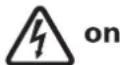
D0000041620
26 02 02 0949
85_02_02_0003_
natural_image
Simple diagram of a circular object with a black bar and two dots, no text or symbols present.26 02 02 0783
26_02_02_1345
26_02_02_1344
natural_image
Technical line drawing of a door switch mechanism showing internal components and directional arrows (no text or symbols)» Avage seade, vabastades selleks fiksaatorluku.
natural_image
Technical line drawing of a mechanical assembly with two views (top and side), showing internal components and directional arrows (no text or symbols)Seinakanduri paigaldamine

natural_image
Mechanical assembly diagram showing a bracket with screws and a rod, mounted on a grid background (no text or symbols)26_02_02_0972
natural_image
Technical diagram showing a mechanical assembly with a screwdriver inserted into a component, no text or symbols present.26_02_02_0950
natural_image
Mechanical diagram showing two configurations of a pulley system with arrows indicating motion direction (no text or labels)26_02_02_0948
natural_image
Technical line drawing of an industrial machine or control unit with internal components and a highlighted section (no text or symbols)D0000041896
natural_image
Technical line drawing of a mechanical device interior with internal components and a close-up inset showing a component detail (no text or symbols present)D0000041897
D0000041925
natural_image
Technical line drawing of a mechanical assembly with no visible text or symbols26 02 02 1348
» Paigaldage tagaseina alaosa tagaseinale ja laske fikseeruda.
natural_image
Technical line drawing of a mechanical device interior with exploded view and component details (no text or symbols)natural_image
Two-step diagram showing a mechanical assembly with cylindrical components and adjustment arrows (no text or symbols)26_02_02_0765
natural_image
Technical diagram of a mechanical assembly with no visible text or symbols26_02_02_1006
natural_image
Diagram of a door switch mechanism with internal components and a downward arrow indicating rotation (no text or symbols)
D0000041620
26 02 02 0949
85_02_02_0003_
26_02_02_1345
26_02_02_1344
natural_image
Technical diagram of a mechanical assembly with no visible text or symbols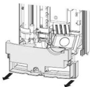
natural_image
Technical line drawing of a mechanical assembly with no visible text or symbolsnatural_image
Technical diagram of a mechanical assembly with mounting holes and a tool, no visible text or symbols26_02_02_0972
natural_image
Technical diagram showing a mechanical bracket and a screwdriver inserted into a component, with no visible text or symbols.natural_image
Mechanical assembly diagram showing two configurations of a bolted joint with pulleys and bolts (no text or labels)26_02_02_0948
natural_image
Technical line drawing of an industrial machine or control unit with internal components and a highlighted section (no text or symbols)D0000041896
natural_image
Technical line drawing of an internal electrical enclosure with visible components and a magnified inset showing a close-up detail (no text or symbols)D0000041897
natural_image
Diagram showing three mechanical components connected by a pipe, with arrows indicating motion direction (no text or symbols)D0000041925
natural_image
Technical line drawing of a mechanical assembly with no visible text or symbols26 02 02 1348
natural_image
Technical diagram of a mechanical device interior with internal components and external wiring (no text or symbols)natural_image
Two-step diagram showing a mechanical assembly with a cylindrical component being inserted, no text or symbols present.26_02_02_0765
natural_image
Technical diagram of a mechanical assembly with no visible text or symbols26_02_02_1006
natural_image
Diagram of a mechanical device with a knob and internal components, showing no text or symbols.
D0000041620
26_02_02_0949
85_02_02_0003_
26_02_02_1345
26_02_02_1344
natural_image
Technical line drawing of a door panel with internal components and directional arrows indicating movement (no text or symbols)natural_image
Technical line drawing of a mechanical assembly with two views (top and side), showing internal components and directional arrows (no text or symbols)natural_image
Mechanical assembly diagram showing a bracket with mounting holes and a rod inserted, mounted on a grid background (no text or symbols)natural_image
Technical diagram showing two mechanical assembly states with arrows indicating direction (no text or symbols)26_02_02_0948
natural_image
Technical line drawing of an industrial machine with internal components and a highlighted section (no text or symbols)D0000041896
natural_image
Technical line drawing of an internal electrical enclosure with visible components and wiring (no text or labels)D0000041897
natural_image
Diagram showing three mechanical components connected by a pipe, with arrows indicating motion direction (no text or symbols)D0000041925
natural_image
Technical line drawing of a mechanical assembly with no visible text or symbols26_02_02_1348
natural_image
Technical line drawing of a mechanical device interior with internal components and a close-up view of the main frame (no text or symbols present)natural_image
Two-step diagram showing a mechanical assembly with cylindrical components and circular components, no text or symbols present.26_02_02_0765
natural_image
Technical diagram of a mechanical assembly with no visible text or symbols26_02_02_1006
natural_image
Diagram of a device with internal components and a scroll arrow indicating rotation (no text or symbols)
D0000041620
26 02 02 0949
85_02_02_0003_
Urzhumskaya street 4,
building 2
129343 Moscow
Tel. 0495 7753889
Fax 0495 7753887
Switzerland
STIEBEL ELTRON AG
Industrie West
Gass 8
5242 Lupfig
Tel. 056 4640-500
Fax 056 4640-501


- Hydraulically controlled instantaneous water heater
- INSTALLATION
- WARRANTY
- ENVIRONMENT AND RECYCLING
- SPECIAL INFORMATION
- OPERATION
- General information
- Safety instructions
- Structure of safety instructions
- Symbols, type of risk
- Keywords
- Other symbols in this documentation
- Units of measurement
- Safety
- Intended use
- General safety instructions
- Test symbols
- Appliance description
- Heating system
- Settings
- Recommended settings when using a thermostatic valve
- Recommended tap/valve settings
- Note
- Following an interruption of the water supply
- Material losses
- Cleaning, care and maintenance
- Troubleshooting
- Safety
- General safety instructions
- Instructions, standards and regulations
- Appliance description
- Standard delivery
- Preparations
- Installation site
- Water installation
- Taps/valves
- Permissible water pipe materials
- Flexible water connection lines
- Installation
- Standard installation
- Making the water connection
- Preparing the back panel
- Installing the appliance
- Making the electrical connection
- Fitting the lower back panel
- Alternative installation options
- Electrical connection from below on unfinished walls
- Material losses If you break out the wrong knock-out by mistake, you should use a new back panel.
- Electrical connection on finished walls
- Connecting a load shedding relay
- Water installation on finished walls
- Completing the installation
- Commissioning
- Appliance handover
- Recommissioning
- Shutting down the system
- Maintenance
- Draining the appliance
- Specification
- Wiring diagram
- DHW output
- Application areas / conversion table
- Pressure drop
- Sizing the pipework
- Fault conditions
- Details on energy consumption
- Guarantee
- REMARQUES PARTICULIÈRES
- UTILISATION
- Materièle schade
- Switzerland
Brand : AEG
Model : DDLT PinControl 18
Category : Heating