
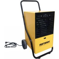
DHA 140 - Humidifier Master - Free user manual and instructions
Find the device manual for free DHA 140 Master in PDF.
| Brand | Master |
| Model | DHA 140 |
| Type | Adsorption dehumidifier |
| Dehumidification capacity | 11 kg/24h (at 20°C, 60% RH) |
| Process air flow | 120 m³/h |
| Regeneration air flow | 40 m³/h |
| Power supply | 230 V ~ 50/60 Hz |
| Power consumption | 780 W |
| Current consumption | 3 A (without built-in ammeter) |
| Sound level | 58 dB(A) |
| Dimensions (W × D × H) | 405 × 315 × 316 mm |
| Weight | 12 kg |
| Operating temperature range | -20 to 40 °C |
| Maximum relative humidity of incoming air | 100% RH |
| Adsorption rotor | Hydrophobic silica gel |
| Air filter | Replace every 2 months (in fixed installation) |
| Electrical connection | 2 m cable with plug (1 Ph+N+PE) |
| Hygrostat adjustment | External connector (hygrostat not supplied) |
| Housing material | Painted steel sheet |
| Maintenance | Clean filter and check rotor rotation monthly |
| Safety | PTC heating units with overheat protection (only operate when air flow is present) |
| Spare parts | Filter, rotor, heating units, fan, gear motor available |
| Warranty | 2 years (parts and labor) |
Frequently Asked Questions - DHA 140 Master
User questions about DHA 140 Master
0 question about this device. Answer the ones you know or ask your own.
Ask a new question about this device
Download the instructions for your Humidifier in PDF format for free! Find your manual DHA 140 - Master and take your electronic device back in hand. On this page are published all the documents necessary for the use of your device. DHA 140 by Master.
USER MANUAL DHA 140 Master
natural_image
Solid dark gray gradient background with no text, symbols, or discernible objectsMCS Italy S.p.A.
Via Tione 12,-37010-
Pastrengo (VR), Italy
info@mcsitaly.it
MCS Central Europe Sp. z o.o.
ul. Magazynowa 5A,
62-023 Gądki, Poland
office@mcs-ce.pl
MCS Russia LLC
ul. Transportnaya - 22 ownership 2,
142802, STUPINO, Moscow region, Russia
info@mcsrussia.ru
MCS China LTD
Unit A1, No. 1515, Jinshao Rd.,
Baoshan Industrial Zone,
Shanghai, 200949, China
office@mcs-china.cn
MCS Italy S.p.A.
Виа Тионе, 12, 37010
MCS Central Europe Sp. z o.o.
ул. Магазинова, 5А,
The dehumidifier removes water from an airflow through, and the removed water is carried away from the dehumidifier with the regeneration air (henceforward called reg.-air). Water adsorption and -extraction takes place in an rotor made of water resistant silica gel. The air flows in the dehumidifier divides the rotor in two parts: drying part and reg.-part.
Two separate air flows goes through the rotor as this:
- the main air (moist air inlet) goes through the drying part, and leaves the dehumidifier as dry air
- the reg.-air is taken from the process air, after passing through two purge sections of the rotor. The air is then heated to app 110°C by the build-in PTC heaters. The warm air then passes through the reg. section of the rotor and removes the adsorbed water (as water vapours). The water vapours and the reg.-air now leaves the dehumidifier through the reg.- air outlet.
The two air flows are fixed and the rotor turns – this gives an automatic process of simultaneous adsorption and water extraction.
▶ FIG. 1:
- filter,
- fan,
- rotor,
- dry air,
- PTC heating element,
- regeneration air outlet,
- drying sector,
- regeneration sector,
- pure sectors.
CAPACITY DIAGRAM (FIG. 5).
The inlet conditions of the air to be dried, determines how much water the dehumidifier will remove.
On the capacity diagram shows how much water will be removed per kg process air.
Example, DHA360: (shown in the diagram - FIG. 5)
- inlet air conditions 20^ , 60% RH , gives water content 8,7g / kg
- the diagram shows then dry air condition of X=5,6 g/kg
- removed per kg air is then: 8,7 - 5.6 = 3,1 g/kg
Capacity DHA360 at this condition:
Dry air flow is nominal
400m^3/h=(x1,2)=480kg/h
Capacity, removed water per hour
= 480x3.1 = 1488 g/h
= 35 kg/24h
Capacity for DHA140 and DHA250 to be calculated in the same way, using 120 and 290 m³/h.
The temperature of the dry air is higher than for the inlet air.
This is caused by the evaporation heat release and heat gain from the rotor. The temperature is shown to be 33^ C.
If bigger specific capacity g/kg is needed, this is possible if the process air is reduced to less than nominal.
▶ 2. APPLICATIONS
Dehumidifiers in the DHA range is used for dehumidification of ambient air at normal atmospheric pressure. This can be an installation for moisture control in an unheated store room, in a water work building, production room for hygro-scopic materials... – with the dehumidifier in a separate installation.
The dehumidifier also can be used as a part of a bigger air treatment system. Here the dehumidifier often will be placed in a by-pass to the main system.
In this case the pressure in the main system will influence the dehumidifier – and your supplier must be contacted, as this can influence the capacity of the dehumidifier.
Normally the dehumidifier will be placed on the floor, on a table or in a wall bracket (option). It should always be placed horizontal, resting on the four pcs. rubber supports.
The air to the dehumidifier should be free from solvents or other explosive components, and should be free from pollution from solid particles, oil vapours and exhaust gases from Diesel engines.
For air to the dehumidifier the following limit values must be respected:
- max. humidity 100%RH
- max. Temperature .... 35°C
- max./min. pressure .... ambient +/-300Pa
The DHA range is for indoor, stationary or temporary installations. Should not be placed in rooms with possibility for free water on the cabinet.
▶ 3. COMPONENTS
REGULATION BY HYGROSTAT
The dehumidifier is prepared for external regulation by a hygrostat. Therefore a special connector for this connection is placed in the cabinet front cover (the black connector).
The male part of the connector can be delivered as option.
The cable for the hygrostat must be connected the male connector, terminals 1,2,PE.
If regulation by hygrostat is needed, simply connect the two connector parts and choose pos. "auto" on the selector switch.
As hygrostat we recommend our DR10*) - 4512.600. Or our electronic hygrostat DA20 - 4512.601.
*) Important:
The DR10 hygrostat must be fixed onto a wall or similar and must not be exposed for condensate or other kind of free liquid.
The hygrostat should be approved for 10A.
ELECTRIC CONNECTION
The dehumidifier is connected 230V, 1Ph+N+PE.
The dehumidifier has a 2m cable with plug for the power supply.
THE INSTALLED ELECTRIC HEATER
The PTC type electric heater is only functioning when air flow through. This is the reason why no thermostats is installed.
WARNING: DO NOT TOUCH THE ELECTRIC HEATER WHEN SWITCHED ON, AS IT IS AN UNINSULATED LIVE WIRE.
The dehumidifier is equipped with PTC heaters.
The energy consumption of the PTC–heater is depending of the air passing through.
At the nominal air flows for the three models, the Amp for the heater is:
The airflow and the energy consumption is regulated on the damper delivered in our standard reg.—duct system (option).
NOTICE: the energy consumption of the electric heater in the first seconds is up to 2x nominal value in 5–10 sec. after switching on the heater.
Special for DHA360:
THE ELECTRONIC TIMER, 10K4 (on delay):
The timer has the following function:
- PTC heater E1 will be switched on 30 sec. after starting-up the dehumidifier (on selector switch or by the hygrostat).
The dehumidifier has two PTC heaters, E1 & E2. Both are the PTC-type, which means that the switch-on Amp is 10A. When starting up the dehumidifier, E2 is immediately switched on. When E2 has reached its nominal Amp (app. 5A) E1 is switched on. In this way the switch-on
Amp. is reduced compared to starting up both heaters at the same time.
▶▶ 4. INSTALLATION
The dehumidifier should be installed indoors, placed on a wall bracket or some other horizontal basis. It should be placed on the four pcs shock absorbers underneath the cabinet.
en
CONNECTION OF DUCTS/HOSES:
The main air to be dried is normally taken from the room and through the main air filter in the back plate.
The air intake is common for process air and reg.air.
As standard the dehumidifier is delivered with filter/filter frame for the common air intake.
Reg.-air outlet should be fitted with duct or hose, Installed draining away from the dehumidifier to allow the condensed water to run free. If this is not possible, a DN4 mm hole should be drilled underneath at the lowest part of the duct.
A damper should be installed too for the adjustment of the nominal reg.air flow (reading the Ammeter).
Dry air outlet can be connected duct or hose with the same size as the outlet on the cabinet. See dimensions on cabinet, FIG. 2, 3, 4.
In general ducts of the same size as placed on the dehumidifier should be used – or bigger.
▶ 5. COMMISSIONING
ELECTRIC
Before starting-up the dehumidifier, check that all electric connections are made correctly.
If this is OK, just connect the plug into the electric switch, and switch on.
DHA140:
The dehumidifier has 2 toggle switches:
– the left one: 0/1 (start/stop),
- the right one: Man/Auto (Auto = hygrostat controlled).
DHA250, 360:
The selector switch SA1 has 3 positions:
- auto = operation controlled by a hygrostat
- 0 = switched off
- man = continuous operation
"Man" means continuous operation.
Especially at "auto" (with connected hygrostat):
- If it does not start-up, it can be caused by the hygrostat.
- If the actual % RH is lower than the set value, the hygrostat contacts are open.
This can be checked like this:
- adjust the hygrostat to 20% RH , and the dehumidifier should then be operating
- adjust the hygrostat to 90% RH , and the dehumidifier should stop operating.
▶▶ 6. AIR FLOWS.
Air flows should be adjusted.
The dry air flow should be adjusted for the nominal m^3/h for obtaining data from the capacity diagram.
If lower dew points are wanted, you need to adjust the dry air flow to values lower than nominal.
HOW TO ADJUST THE AIRFLOWS:
– the dry air flow can be adjusted on the optional damper in the dry air outlet. The airflow must be measured be
en
measured and adjusted on the damper for the nominal value.
Free blowing, the capacity in kg/h will increase: If the demand for very dry air is not needed, the dehumidifier should then operate free blowing
- the reg.- air flow can be adjusted on the damper in the reg.-air outlet (option). Start-up with the damper in the closed position, opening until the Ammeter indicates:
Notice: DHA140 has no Ammeter installed and the Amp must be measured using an Ampere instrument.
IMPORTANT :
Reg.-air flow always has to be controlled. Check the reg.-duct for allowing free blowing of the reg.-air.
Check that the reg.-air duct is installed draining from the dehumidifier.
SPECIAL FOR DHA360:
STARTING-UP OF THE HEATERS:
The two heaters E1 & E2 starts up with 10K4 delaying E1 with 30 seconds.
On the Am–meter this will be indicated like this:
- when the dehumidifier is switched on, the Am.meter shows 10A in app. 5 sec., and fall down to 5A.
- after 30 sec. E1 is switched on and the Ammeter show app. 18A for 5 sec., and then it fall down to 8,00A with the reg-air correctly adjusted.
With the electrical settings and air flows adjusted, the dehumidifier will then operate automatically by means of the internal control- and safety functions - controlled by an external hygrostat.
▶ 7. MAINTENANCE
The DHA dehumidifiers only needs a minimum of maintenance. All components are service free, which means no lubrication or adjustment.
Only three things should be checked under normal operation:
- air filter should be replaced at least every 2 months if stationary installed. At renting the dust level might be high and the filter must be replaced often – and the cabinet and rotor should be cleaned after each period,
- the rotation of the rotor should be checked once a month,
- the power consumption of the electric heater should be checked often (reading on the Ammeter, Excl. DHA140)).
Rotation of the rotor can be checked through the dry air outlet if no duct is connected). The rotor should then turn clockwise.
If the rotor rotates during operation, and the energy consumption of the electric heater shows nominal Amp, you can be almost sure that the dehumidifier is operating at an optimum. We nevertheless recommend some periodic verification of the entire dehumidifier, to see if all internal functions are OK and checking of gaskets and moving parts for wear and tear.
This will ensure that the capacity is on its maximum, and thus won't waste any energy.
▶▶ 8. TROUBLE SHOOTING
IF THE DEHUMIDIFIER DOES NOT START WHEN ELECTRIC CONNECTED:
▶ check the external fuse
IF THE DEHUMIDIFIER IS NOT OPERATING IT IS PROBABLY THE EXTERNAL HYGROSTAT WHICH HAS BROKEN:
This is a normal situation when the desired humidity is obtained. To check: adjust the hygrostat for 20%RH, and the dehumidifier should start operating. Adjust again for the desired humidity.
IF THE DESIRED HUMIDITY IS NOT OB- TAINED:
▶ The problem can be the dehumidifier – or the other parts in the total installation (room tightness, hygrostat...). To verify this, check:
- rotation of rotor ?
- the dry air should be 15–20°C warmer than the inlet main air. If it is cold it could indicate that the rotor is not turning caused by broken drive belt or the motor has stopped.
- by hand feel the temperature of the reg. outlet air, and feel the airflow. The temperature is depending on the inlet conditions, but should be 40–60°C.
▶ If the temperature is higher it could indicate that the rotor is not turning.
▶ Check the Ammeter reading, must be nominal value:
If it is cold and Ammeter shows 0A, the electric heater might need replacement.
THE UNIT IS TOO NOISY:
▶ Check whether the unit is sitting on a level surface.
THE UNIT IS LEAKING:
▶ Make sure the unit is in good shape.
▶ If you are not using continuous drainage, make sure the rubber plug (at the bottom of the unit) is in its position.
▶ 9. SERVICE/REPAIR
SAFETY INSTRUCTION
Before opening the dehumidifier, make sure that the electric power is switched off on the main switch. Pull the power plug to be sure.
REPLACING THE ELECTRIC HEATERS DHA140:
Remove the cabinet top cover.
Remove the internal hose for the reg-air outlet.
Release the total internal assembly, and pull it out of the cabinet.
The PTC heater is now accessible for replacing.
DHA250, DHA360:
When the small cover in the front of the dehumidifier is removed, the two PTC heaters are accessible for replacing.
REPLACING OF GEARMOTOR, AMMETER, HOURCOUNTER, SELECTOR SWITCH
Remove the cabinet top cover.
Remove the cabinet front cover. All cables to the dehumidifier (fan, gear motor and heaters) are to be unscrewed by the terminals.
Now the cabinet front cover is free to be unscrewed and the components accessible for replacing.
REPLACING OF FAN
DHA140:
Remove the cabinet top cover.
Remove the internal hose for the reg-air outlet.
Release the total internal assembly, and pull it out of the cabinet.
The fan is now accessible for replacement.
DHA250, DHA360:
Remove the cabinet top plate. The fan is placed on the fan plate, and can easily be pulled up and out of the cabinet.
Disconnect the electric connection (separate the plug).
REPLACING OF ROTOR
DHA140:
Remove the cabinet top cover.
Remove the internal hose for the reg-air outlet.
Release the total internal assembly, and pull it out of the cabinet.
The rotor is now accessible for replacement.
DHA250, DHA360:
Remove the top plate and pull the fan up and out of the cabinet.
Remove the hose by pulling it off the duct connections
Remove the two springs on the small shafts by unscrewing the screws
Unscrew the screw in the rotor shaft, remove the washer and the spring.
Now the dividing plate with the reg.air connector can be pulled off the shafts, and the rotor is free for replacing too.
REPLACING THE FILTER
For replacing the filter in the air inlet, remove the screws and the net. Now the filter can be taken out and a new one installed.
INDICE
É RILEVATA UNA PERDITA DAL DISPOSITIVO:
RACCORDEMENT DE CABLES/FLEXIBLES:
REPLACEMENT DU ROTOR
DHA140:
▶▶ 6. LUFTGENNEMSTRÖMNINGER.
Luftgennemstrømninger skal reguleres.
▶▶ 9. SERVICE/REPARATION
SIKKERHEDSVEJLEDNING
▶▶ 1. TOIMINNAN KUVAUS
▶▶ 9. HUOLTO/KORJAUKSET
TURVAÖHJE
REGULERING MED HYGROSTAT
HVIS AVFUKTEREN IKKE FUNGERER, ER SANNSYNLIGVIS DEN EKSTERNE HYGRO-STATEN SKADET:
APPARATET LAGER FOR MYE ST∅Y:
WYKRES WYDAJNOŚCI (FIG. 5).
▶▶ 6. PRZEPLYWY POWIETRZA
- bal: 0/1 (start/stop),
É RILEVATA UNA PERDITA DAL DISPOSITIVO:
▶▶ 9. TEENINDUS/REMONT OHUTUSJUHIS
DHA 140
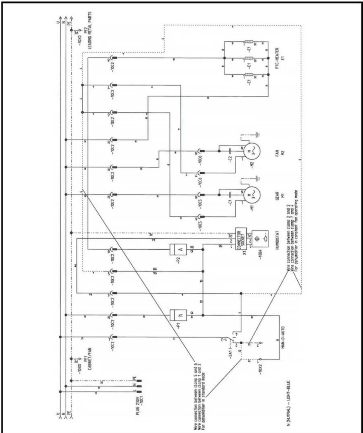
SKEMA ELEKTRIKE - ELEKTRIYCECKA CXEMA - 电路图 - ELEKTRICKÉ SCHÉMA - ELEKTRISCHES SCHALTBILD - EL-DIAGRAM - ELEKTRISKEEM - ESQUEMA ELÉCTRICO - KYTKENTÄKAAVIO - SCHÉMA DE CÂBLAGE - WIRING DIAGRAM - ΣXEIAΓPAMMA TOY HΛEKTRIKOY KYKA{MATOΣ - SHEMA ELEKTRIKE - ELEKTROMOS KAPCSOLÁSI SÉMA - SCHEMA ELETTRICO - ELEKTRINE SCHEMA - ELEKTRISKÄ SHÊMA - SCHAKELSCHEMA - ELEKTRISK SKJEMA - SCHEMAT ELEKTRYCZNY - ESQUEMA ELÉTRICO - SCHEMA ELECTRICÄ - ЭЛЕКТРИЧЕСКАЯ CXEMA - ELANLÄGGNING - ELEKTRICNA SHEMA - ELEKTRICKÄ SCHÉMA - ELEKTRDK SEMASI - ELEKTRIYCHA CXEMA - SHEMA ELEKTRIKE
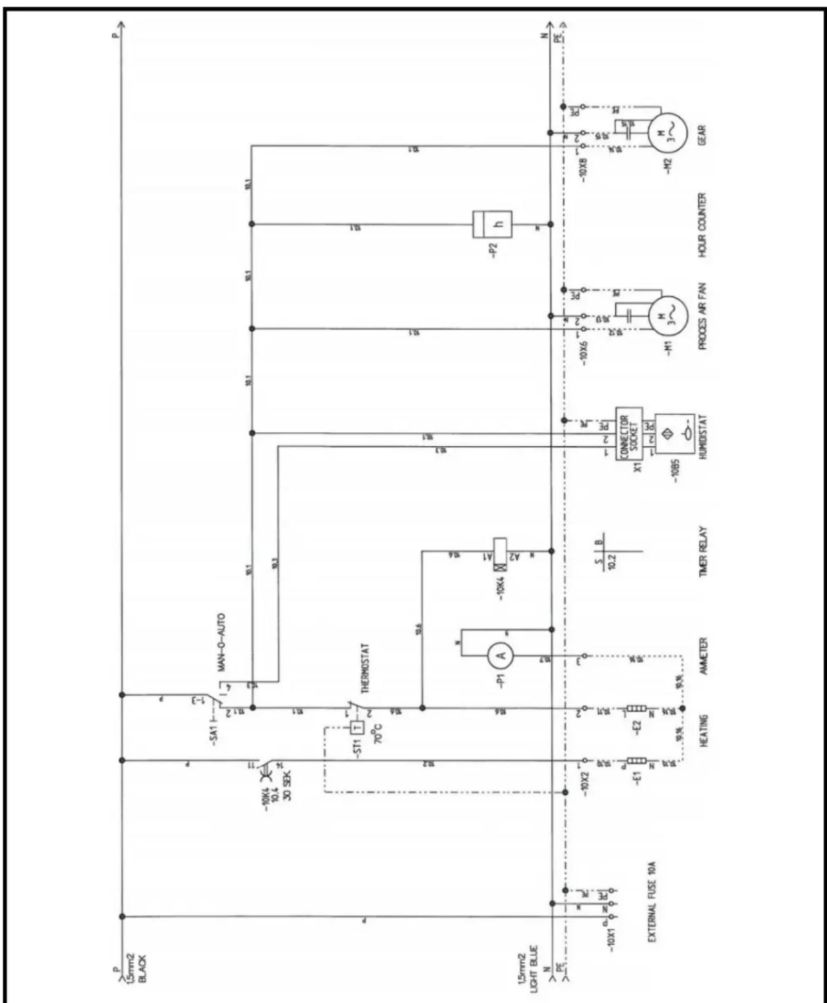
DHA 250
SKEMA ELEKTRIKE - ЕЛЕКТРИЧЕСКА СХЕМА - 电路图 - ELEKTRICKÉ SCHÉMA - ELEKTRISCHES SCHALTBILD - EL-DIAGRAM - ELEKTRISKEEM - ESQUEMA ELÉCTRICO - KYTKENTÄKAAVIO - SCHÉMA DE CÂBLAGE - WIRING DIAGRAM - ΣXEIΑΓΡΑΜΜΑ ΤΟΥ ΗΛΕΚΤΡΙΚΟΥ ΚΥΚΛ{ΜΑΤΟΣ - SHEMA ELEKTRIKE - ELEKTROMOS KAPCSOLÁSI SÉMA - SCHEMA ELETTRICO - ELEKTRINE SCHEMA - ELEKTRISKÄ SHÊMA - SCHAKELSCHEMA - ELEKTRISK SKJEMA - SCHEMAT ELEKTRYCZNY - ESQUEMA ELÉTRICO - SCHEMA ELECTRICÄ - ЭЛЕКТРИЧЕСКАЯ СХЕМА - ELANLÄGGNING - ELEKTRICÑA SHEMA - ELEKTRICKÁ SCHÉMA - ELEKTRDK SEMASI - ЕЛЕКТРИЧНА СХЕМА - SHEMA ELEKTRIKE
DHA 360
AL DEKLARATA E PËRSHTATJES TË BE
FR DÉCLARATION CE DE CONFORMITÉ
GB EC DECLARATION OF CONFORMITY
MCS Central Europe Sp. z o.o.
2006/42/EC, 2006/95/EC, 2004/108/EC
AL dhe normë BG И норми CN 的指令和规范 CZ A normami DE und Normen DK og standarder EE ja normidele ES y las normativas FI ja normit FR et aux normes GB and norms GR και πρότυτα HR i standarde HU és szabványoknak IT e norme LT ir normas LV un normäm NL en normen NO og normer PL i normy PT e normas RO și normele cerute RU и норм SE och normer SI in normami SK a normami TR beyan ederiz UA i норм YU i standarde
EN 12100-1, EN 12100-2, EN 60204-1, EN 61000-6-4, EN 61000-6-2
Stefano Verani
CEO MCS Group
Gądki, 02-01-2014 / CE-14
GB – Disposal of your old product
- You product is designed and manufactured with high quality materials and components, which can be recycled and reused.
- When this crossed-out wheeled bin symbol is attached to a product it means the product is covered by the European Directive 2002/96/EC.
- Please inform yourself about the local separate collection system for electrical and electronic products.
- Please act according to your local rules and do not dispose of your old product with your normal household waste. The correct disposal of your old product will help prevent potential negative consequences for the environment and human health.

- MCS Italy S.p.A.
- MCS Central Europe Sp. z o.o.
- MCS Russia LLC
- MCS China LTD
- CAPACITY DIAGRAM (FIG. 5).
- Capacity DHA360 at this condition:
- ▶ 2. APPLICATIONS
- ▶ 3. COMPONENTS
- REGULATION BY HYGROSTAT
- ELECTRIC CONNECTION
- THE INSTALLED ELECTRIC HEATER
- WARNING: DO NOT TOUCH THE ELECTRIC HEATER WHEN SWITCHED ON, AS IT IS AN UNINSULATED LIVE WIRE.
- Special for DHA360:
- THE ELECTRONIC TIMER, 10K4 (on delay):
- ▶▶ 4. INSTALLATION
- CONNECTION OF DUCTS/HOSES:
- ▶ 5. COMMISSIONING
- ELECTRIC
- DHA140:
- DHA250, 360:
- ▶▶ 6. AIR FLOWS.
- HOW TO ADJUST THE AIRFLOWS:
- IMPORTANT :
- STARTING-UP OF THE HEATERS:
- ▶ 7. MAINTENANCE
- ▶▶ 8. TROUBLE SHOOTING
- IF THE DEHUMIDIFIER DOES NOT START WHEN ELECTRIC CONNECTED:
- IF THE DEHUMIDIFIER IS NOT OPERATING IT IS PROBABLY THE EXTERNAL HYGROSTAT WHICH HAS BROKEN:
- IF THE DESIRED HUMIDITY IS NOT OB- TAINED:
- THE UNIT IS TOO NOISY:
- THE UNIT IS LEAKING:
- ▶ 9. SERVICE/REPAIR
- SAFETY INSTRUCTION
- REPLACING THE ELECTRIC HEATERS DHA140:
- DHA250, DHA360:
- REPLACING OF GEARMOTOR, AMMETER, HOURCOUNTER, SELECTOR SWITCH
- REPLACING OF FAN
- REPLACING OF ROTOR
- REPLACING THE FILTER
- INDICE
- É RILEVATA UNA PERDITA DAL DISPOSITIVO:
- RACCORDEMENT DE CABLES/FLEXIBLES:
- REPLACEMENT DU ROTOR
- ▶▶ 6. LUFTGENNEMSTRÖMNINGER.
- ▶▶ 9. SERVICE/REPARATION
- SIKKERHEDSVEJLEDNING
- ▶▶ 1. TOIMINNAN KUVAUS
- ▶▶ 9. HUOLTO/KORJAUKSET
- TURVAÖHJE
- REGULERING MED HYGROSTAT
- HVIS AVFUKTEREN IKKE FUNGERER, ER SANNSYNLIGVIS DEN EKSTERNE HYGRO-STATEN SKADET:
- APPARATET LAGER FOR MYE ST∅Y:
- WYKRES WYDAJNOŚCI (FIG. 5).
- ▶▶ 6. PRZEPLYWY POWIETRZA
- ▶▶ 9. TEENINDUS/REMONT OHUTUSJUHIS
- 2006/42/EC, 2006/95/EC, 2004/108/EC
- EN 12100-1, EN 12100-2, EN 60204-1, EN 61000-6-4, EN 61000-6-2
- GB – Disposal of your old product
Brand : Master
Model : DHA 140
Category : Humidifier