BAR688HG - Weather Station OREGON SCIENTIFIC - Free user manual and instructions
Find the device manual for free BAR688HG OREGON SCIENTIFIC in PDF.


User questions about BAR688HG OREGON SCIENTIFIC
0 question about this device. Answer the ones you know or ask your own.
Ask a new question about this device
Download the instructions for your Weather Station in PDF format for free! Find your manual BAR688HG - OREGON SCIENTIFIC and take your electronic device back in hand. On this page are published all the documents necessary for the use of your device. BAR688HG by OREGON SCIENTIFIC.
USER MANUAL BAR688HG OREGON SCIENTIFIC
Wireless Weather Station with Temperature / Humidity, Ice Alert
and Radio-Controlled Clock
Model: BAR688HG
USER MANUAL
P/N:086L004344-058 REV 1 1/94
Wireless Weather Station with Temperature / Humidity, Ice Alert and Radio-Controlled Clock Model: BAR688HG
USER MANUAL
CONTENTS
Contents.... 1
Introduction.... 2
Clock Overview.... 2
Front View.... 2
Back View.... 2
LCD Display 3
Remote Sensor (THGN122N).... 4
Getting Started.... 4
Batteries.... 4
Remote Sensor.... 4
Sensor Data Transmission.... 6
Clock 6
Clock Reception.... 6
Reception Signal 6
P/N:086L004344-058 REV 12/94
Set Clock.... 6
Alarm.... 7
Barometer.... 7
Set Altitude.... 7
Weather Forecast.... 7
Temperature and Humidity.... 8
Temperature, Humidity And Pressure Trend..... 8
Ice Warning 8
Hi / Lo Temperature / Humidity Alarms.... 8
Heat Index...... 8
Comfort Zone.... 9
Moon Phase.... 9
Reset.... 9
Precautions 10
Specifications.... 10
About Oregon Scientific.... 11
EU-Declaration of Conformity.... 11
INTRODUCTION
Thank you for selecting this Oregon Scientific Wireless Weather Station with Temperature / Humidity, Ice Alert and Radio-Controlled Clock (BAR688HG). This clock is supplied with a remote sensor (THGN122N) and can support up to 3 sensors in total (additional sensors sold separately).
NOTE Please keep this manual handy as you use your new product. It contains practical step-by-step instructions, as well as technical specifications and warnings you should know about.
CLOCK OVERVIEW
FRONT VIEW
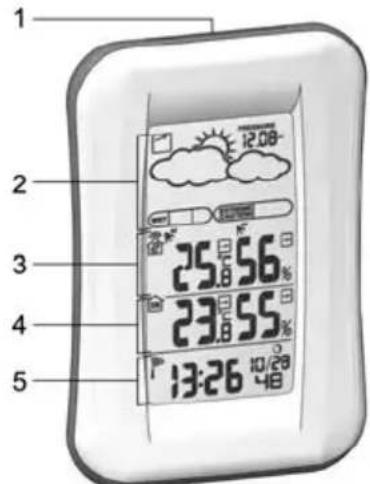
text_image
1 2 3 4 5 25.8 56% 23.8 55% 13:26 10/28 48P/N:086L004344-058 REV 1 3/94
- SNOOZE
- Weather Forecast Area
- Outdoor Temperature Area
- Indoor Temperature Area
- Clock / Alarm Area
BACK VIEW
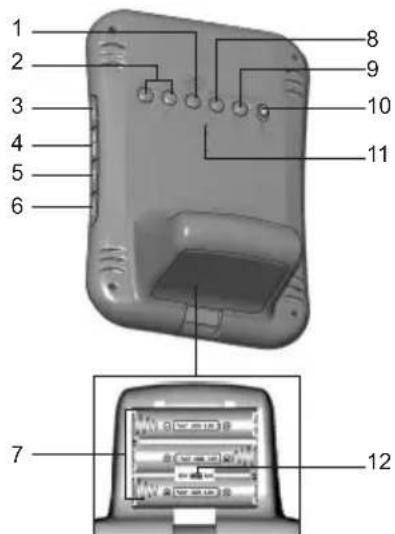
text_image
1 2 3 4 5 6 8 9 10 11 7 12- TEMP / HUMIDITY HI / LO ▶ Change settings or enable / disable hi or lo temperature / humidity alarm for channel 1
- ▲ / ▼: Increase / decrease setting; activate / deactivate clock reception signal
- CHANNEL: Switch remote sensor display
- HEAT INDEX: Display heat index
-
MODE: Change settings / display
-
ALARM: View alarm status; set alarm
- Battery compartment
- MEM : View current, maximum and minimum temperature / humidity
- PRESSURE: Select pressure unit; set altitude
- °C / °F: Select temperature unit
- RESET: Reset unit to default settings
- EU / UK switch
LCD DISPLAY
Weather Forecast Area:
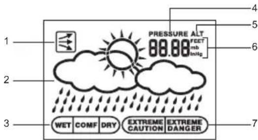
text_image
1 2 3 WET COMF DRY EXTREME CAUTION EXTREME DANGER PRESSURE ALT 00.00 FEET mb InHg 4 5 6 7- Pressure trend
- Weather forecast
- Comfort zone
- Pressure icon
- Altitude icon
- Pressure / altitude unit
- UV index icon
P/N:086L004344-058 REV 14/94
Outdoor Temperature Area:
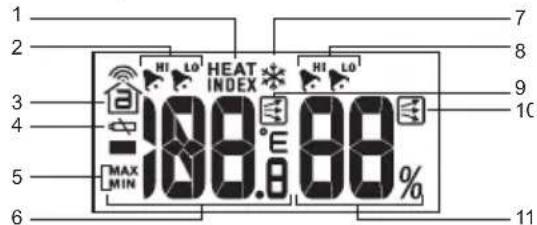
text_image
1 2 3 4 5 6 7 8 9 10 MAX MIN HEAT INDEX HI LO 100.8° 88% 11- Heat index icon
- Hi / lo temperature alarm
- Sensor reception icon
- Sensor battery low
- Max / min icon
- Temperature display
- Ice warning is active
- Hi / lo humidity alarm
- Temperature trend
- Humidity trend
- Humidity display
Indoor Temperature Area:
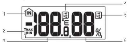
text_image
1 IN -188.0 88% MAX MIN 2 3 4 5 6- Indoor sensor icon
- Max / min icon
- Temperature display
- Temperature trend
- Humidity trend
- Humidity display
Clock / Alarm Area:
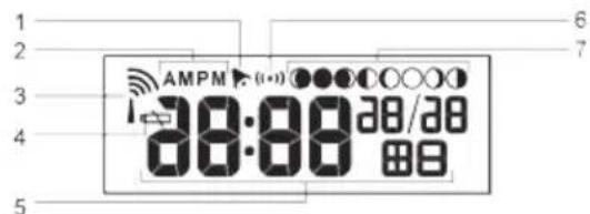
text_image
AMPM (1:00) 38:00 28/28 6 7- Alarm set
- AM / PM icon
- Clock signal reception
- Low battery icon
- Clock
- Alarm mode icon
- Moon phase
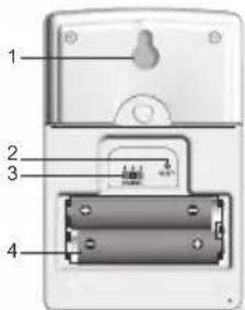
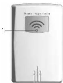
REMOTE SENSOR (THGN122N)
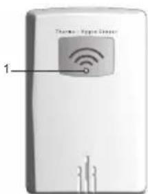
text_image
Thermostable Internet 1- LED status indicator: Blinks red during data transmission
text_image
1 2 3 4- Wall mount hole
- RESET hole
- CHANNEL switch
- Battery compartment
P/N:086L004344-058 REV 1 5/94
GETTING STARTED
BATTERIES
Insert batteries before first use, matching the polarity (+ and -). Press RESET after each battery change.
natural_image
Close-up of a gray ergonomic computer mouse with a curved arrow on the handle (no text or symbols visible)
natural_image
Close-up of a battery pack with four black battery symbols on one side (no text or labels visible)
indicates main unit batteries are low.
NOTE Do not use rechargeable batteries. We recommend that you use alkaline batteries with this product for longer usage and lithium batteries in temperatures below freezing.
REMOTE SENSOR
The sensor collects temperature readings approx. every 40 seconds and sends them to the main unit. The main unit can collect data from up to 3 sensors.
To set up the sensor:
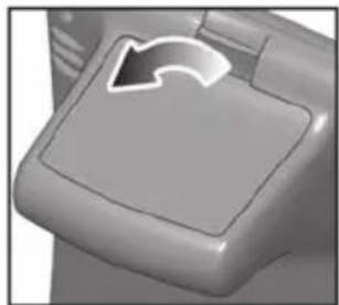
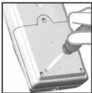
- Remove the screws from the battery door.
- Insert the batteries, matching the polarity (+ / -).
natural_image
Close-up of a hand using a tool to apply material to a component with mounting holes (no visible text or symbols)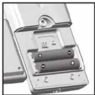
natural_image
Close-up of a battery pack with two batteries and a switch (no visible text or symbols)- Select a channel. Make sure you use a different channel for each sensor.
- Place the sensor near the main unit. Press RESET on the sensor.
- Simultaneously press CHANNEL and MEM on the main unit to initiate signal sending between the sensor and main unit.
- Close the battery door and secure the screws.
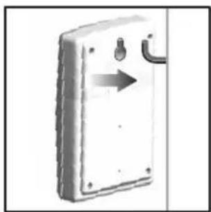
- Place the sensor in the desired location using the table stand or wall mount.
natural_image
Exterior view of a white rectangular electronic device with a curved handle and arrow indicating direction (no text or symbols)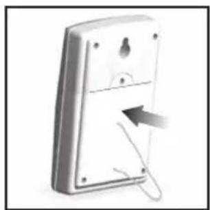
natural_image
3D rendering of a white remote control panel with a paperclip and arrow indicating left side (no text or symbols)P/N:086L004344-058 REV 16/94
For best results:
- Place the sensor out of direct sunlight and moisture.
- Do not place the sensor more than 30 m (100 ft) from the main (indoor) unit.
- Position the sensor so that it faces the main (indoor) unit, minimizing obstructions such as doors, walls, and furniture.
- Place the sensor in a location with a clear view to the sky, away from metallic or electronic objects.
- Position the sensor close to the main unit during cold winter months as below-freezing temperatures may affect battery performance and signal transmission.
The transmission range may vary depending on many factors. You may need to experiment with various locations to get the best results.
Standard Alkaline batteries contain significant amounts of water. Because of this they will freeze in low temperatures of approximately -12°C (10°F). Disposable Lithium batteries have a much lower threshold for temperature with an estimated freezing range of below -30°C (-22°F).
Wireless ranges can be impacted by a variety of factors such as extremely cold temperatures. Extreme cold may temporarily reduce the effective range between the sensor and the base station. If the unit's performance fails due to low temperature, the unit will resume proper functioning as the temperature rises to within the normal temperature range (i.e. no permanent damage will occur to the unit due to low temperatures).
SENSOR DATA TRANSMISSION
The sensor reception icon in the remote sensor area shows the status.
| ICON | DESCRIPTION |
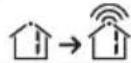 | Main unit is searching for the sensor(s) |
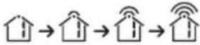 | A channel has been found and sensor signal is being received |
 temperature Area) temperature Area) | The sensor cannot be found. Search for the sensor or check batteries |
To search for a sensor:
Simultaneously, press and hold MEM and CHANNEL for 2 seconds.
NOTE If the sensor is still not found, check the batteries, obstructions, and remote unit location.
CLOCK
CLOCK RECEPTION
This product is designed to synchronize its date and time automatically once it is within range of :
- DCF-77 generated from Frankfurt, Germany for Central Europe.
• MSF-60 generated from Anthorn, England.
P/N:086L004344-058 REV 17/94
The clock collects the radio signals whenever it is within 1500 km (932 miles) of a signal.
NOTE Slide the EU / UK switch to appropriate position for your location. Repeat each time you reset the unit.
NOTE Initial reception takes 2-10 minutes for first set up or when RESET is pressed. Once complete, the reception icon will stop blinking. If the signal is weak, it can take up to 24 hours to get a valid signal.
RECEPTION SIGNAL
Clock signal reception indicator:
| STRONG SIGNAL | WEAK SIGNAL | NO SIGNAL |
To enable and force a signal search:
Press and hold ▲ for 2 seconds.
To disable the signal reception:
Press and hold ▼ for 2 seconds.
SET CLOCK
If the clock signal reception is enabled and a signal is being received the clock does not need to be manually set.
- Press and hold MODE for 2 seconds.
-
Press ▲ or ▼ to change the settings.
-
Press MODE to confirm.
- The settings order is: time zone offset, hour, minute, year, month, day and language.
NOTE The time zone offset can be used to set the clock up to + / - 9 hours from the received clock signal time. If you have disabled the clock signal reception (i.e. manually setting the clock), do not set a value for time zone offset.
NOTE The language options are English (E), German (D), French (F), Italian (I), and Spanish (S).
Press MODE to choose between the clock with seconds and clock with weekday display modes.
ALARM
To set the alarm:
- Press and hold ALARM for 2 seconds.
- Press ▲/▼ to set hour / minute.
- Press ALARM to confirm. indicates alarm is ON.
To toggle alarms ON / OFF:
- Press ALARM to display alarm time.
- Press ALARM again to turn alarm ON / OFF.
To silence the alarm:
- Press SNOOZE to silence it for 8 minutes.
OR - Press any key except SNOOZE to turn the alarm off and activate it again after 24 hours.
P/N:086L004344-058 REV 18/94
BAROMETER
Barometer readings from the past 24 hours are stored by the main unit and used to provide weather forecast.
To select barometer measurement unit:
Press PRESSURE to toggle between mb and inHg.
SET ALTITUDE
To ensure barometric readings are reliable set the altitude to reflect distance from sea level at your position.
- Press and hold PRESSURE for 2 seconds.
- Use ▲ and ▼ to set the altitude in 10 m (33 ft) increments from 100 m (328 ft) to 2500 m (8202 ft).
- Press PRESSURE to confirm.
WEATHER FORECAST
This product forecasts the next 12 to 24 hours of weather within a 30-50 km (19-31 mile) radius based on barometric pressure trend readings.
| ICON | DESCRIPTION |
| Clear | |
| Partially Cloudy | |
| Cloudy | |
| Rainy |
TEMPERATURE AND HUMIDITY
To toggle temperature unit:
Press °C / °F.
To view outdoor sensors temperature readings:
Press CHANNEL.
To auto-scan between sensors:
Press and hold CHANNEL for 2 seconds.
Each sensor's data is displayed for 3 seconds.
To end auto-scan:
Press CHANNEL or MEM.
To toggle between current, minimum and maximum records for the selected sensor:
Press MEM repeatedly.
To clear the records:
Press and hold MEM for 2 seconds.
TEMPERATURE, HUMIDITY AND PRESSURE TREND
The temperature, humidity and pressure trend icons are based on recent sensor readings.
If the channel 1 sensor falls between 3^ C to -2^ C ( 37^ F to 28^ F), ✕ flashes to warn you that the temperature is approaching freezing.
NOTE The warning will automatically stop if the temperature goes outside the ice-warning range.
HI / LO TEMPERATURE / HUMIDITY ALARMS
Temperature and humidity alerts can be set to sound if sensor set to channel 1 records above or below a temperature/humidity of your choice.
To set alarm ON / OFF:
- Press and hold TEMP / HUMIDITY HI / LO ▶.
- Use ▲ and ▼ to select high / low temperature / humidity alarm. Press TEMP / HUMIDITY HI / LO ▶ to confirm.
- Press ▲/▼ to set alarm ON/OFF and press TEMP / HUMIDITY HI/LO▶ to confirm.
- If alarm has been activated, use ▲ and ▼ to select the temperature / humidity.
- Press TEMP / HUMIDITY HI / LO to confirm.
To silence the hi / lo alarm:
Press any key. The alarm resets automatically and will resound if the hi / lo temperature is recorded again.
HEAT INDEX
The heat index combines temperature and humidity data to describe the actual temperature felt.
| WARNING | HEAT INDEX | MEANING |
| Extreme danger | 54.5°C / (130°F) or above | Strong risk of dehydration / sun stroke |
| Danger | 40.5 - 54°C (105 - 129°F) | Heat exhaustion likely |
| Extreme caution | 32.2 - 40°C (90 - 104°F) | Possibility of heat dehydration |
| Caution | 26.6 - 31.7°C (80 - 89°F) | Possibility of heat exhaustion |
• To display the heat index, press HEAT INDEX.
- To toggle between current / maximum / minimum readings, press HEAT INDEX, then press CHANNEL to select channel 1-3 or indoor, followed by MEM.
- To toggle between temperature / humidity and heat index display, press and hold HEAT INDEX for 2 seconds. Press HEAT INDEX again to stop this feature.
NOTE If the heat index is below 80^ F / 26^ C, or the desired channel is not working, the heat index will display NA.
COMFORT ZONE
The comfort zone assesses the climate based on current temperature and humidity measurements.
| ICON | TEMPERATURE | HUMIDITY |
| >70%Any | ||
| 20 - 25°C(68 - 77°F) | 40 - 70% | |
| < 40%Any |
MOON PHASE
- When calendar is set press ▲ or ▼ to view the moon phase for the next / previous day.
- Press and hold or to scan through the years (2001 to 2099).
| ● | New Moon |
| ○ | Waxing Crescent |
| ○ | First Quarter |
| ○ | Waxing Gibbous |
| ○ | Full Moon |
| ○ | Waning Gibbous |
| ○ | Last Quarter |
| ○ | Waning Crescent |
RESET
Press RESET to return the unit to the default settings.
PRECAUTIONS
This product is engineered to give you years of satisfactory service if you handle it carefully. Here are a few precautions:
- Do not subject the unit to excessive force, shock, dust, temperature or humidity, which may result in malfunction, shorter electronic life span, damaged battery and distorted parts.
- Do not immerse the unit in water. If you spill liquid over it, dry it immediately with a soft, lint-free cloth.
- Do not clean the unit with abrasive or corrosive materials.
- Do not tamper with the unit's internal components. Doing so will invalidate the warranty on the unit and may cause unnecessary damage. The unit contains no user-serviceable parts.
- Only use fresh batteries as specified in the user's instructions. Do not mix new and old batteries.
- Due to printing limitations, the displays shown in this manual may differ from the actual display.
- The contents of this manual may not be reproduced without the permission of the manufacturer.
- Do not dispose this product as unsorted municipal waste. Collection of such waste separately for special treatment is necessary.
NOTE The technical specifications for this product and the contents of the user manual are subject to change without notice.
SPECIFICATIONS
| TYPE | DESCRIPTION |
| MAIN UNIT | |
| L x W x H | 117 x 80 x 171 mm(4.78 x 3.27 x 6.98 in) |
| Weight | 241 g (8.5 oz) without battery |
| Temperature unit | °C / °F |
| Temperature range | -5°C to 50°C (23°F to 122°F) |
| Resolution | 0.1°C (0.2°F) |
| Clock frequency | DCF-77(EU) / MSF-60(UK) |
| Synchronization | Auto or disabled |
| Signal frequency | 433 MHz |
| Clock | Auto or manual (disabled) |
| Humidity range | 25% - 95% |
| Humidity resolution | 1% |
| Memory | Min / Max relative humidity and temperature |
| Alarm duration | 2 minutes |
| Snooze | 8 minutes |
| Clock display | HH:MM:SSHH:MM: Day of Week |
| Hour format | 12 / 24 hour format |
| Calendar | MM / DD or DD / MMlanguage selectable:E, D, F, I and S |
| Power | 3 x UM-3 (AA) 1.5 V batteries |
REMOTE UNIT
| L x W x H | 92 x 60 x 20 mm(3.6 x 2.4 x 0.8 in) |
| Weight | 62 g (2.22 oz) |
| Transmission range | 30 m (100 ft) unobstructed |
| Temperature range | -30°C to 60°C(-22°F to 140°F) |
| Power | 2 x UM-4 (AAA) 1.5 V batteries |
NOTE We recommend that you use alkaline batteries with this product for longer usage and lithium batteries in temperatures below freezing.
ABOUT OREGON SCIENTIFIC
Visit our website (www.oregonscientific.com) to learn more about Oregon Scientific products. If you're in the US and would like to contact our Customer Care department directly, please visit:
www2.oregonscientific.com/service/support.asp OR
Call 1-800-853-8883.
For international inquiries, please visit: www2.oregon scientific.com/about/international.asp.
EU-DECLARATION OF CONFORMITY
Hereby, Oregon Scientific, declares that the Wireless Weather Station with Temperature / Humidity, Ice Alert and Radio-Controlled Clock (Model BAR688HG) is in compliance with the essential requirements and other relevant provisions of Directive 1999/5/EC.
P/N:086L004344-058 REV 1 12/94
A copy of the signed and dated Declaration of Conformity is available on request via our Oregon Scientific Customer Service.
text_image
Theme - Signal Server 1natural_image
Close-up of a gray mechanical component with a white curved arrow on the top surface (no text or symbols visible)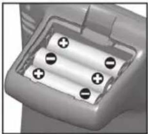
natural_image
Close-up of a battery pack with four white segments and four black battery cells (no text or symbols visible)natural_image
Close-up of a hand using a tool to apply material to a component with mounting holes (no visible text or symbols)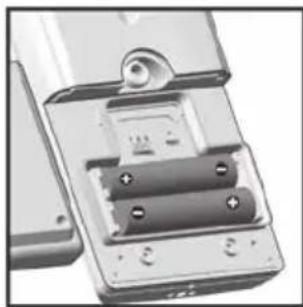
natural_image
Close-up of a mechanical device with two batteries and a lock (no visible text or symbols)natural_image
Simple line drawing of a door with an arrow indicating left motion (no text or symbols)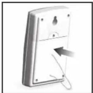
natural_image
Illustration of a remote control panel with a cable inserted, showing no text or symbols on the panel itself.P/N:086L004344-058 REV 1 17/94
text_image
1 2 3 4 5 25.56% 23.55% 13:26 10/29 48P/N:086L004344-058 REV 126/94
text_image
Theme - Signal Server 1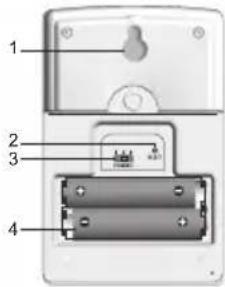
text_image
1 2 3 4natural_image
Close-up of a gray ergonomic computer mouse with a white curved arrow pointing to the handle area (no text or symbols visible)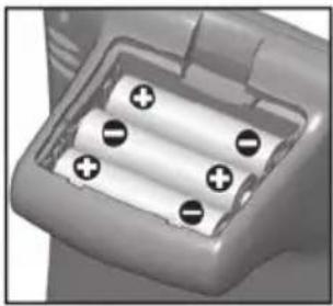
natural_image
Close-up of a battery pack with four black battery symbols on its side (no text or labels visible)
natural_image
Close-up of a hand using a tool to adjust or install a component on a metallic device (no visible text or symbols)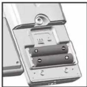
natural_image
Close-up of a battery pack with two batteries and a switch (no visible text or symbols)natural_image
Diagram of a door switch with an arrow indicating left motion (no text or symbols)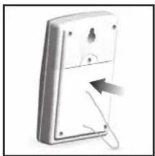
natural_image
3D rendering of a remote control panel with a paperclip and arrow indicating cable attachment (no text or symbols)P/N:086L004344-058 REV 1 29/94
www2.oregonscientific.com/service/support.asp OU
text_image
1 2 3 4 5 12:08- 25.56% 23.55% 13:26 10/29 48P/N:086L004344-058 REV 1 38/94
text_image
1 2 3 4 5 6 7 8 9 10 MAX MIN HEAT INDEX MAX LO 108.6°E 88% 11natural_image
Close-up of a gray mechanical component with a white curved arrow pointing to a specific area (no text or symbols visible)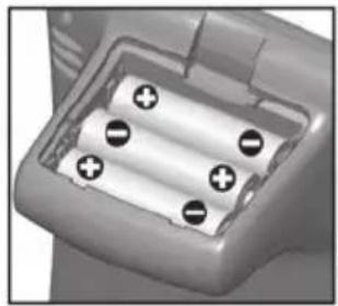
natural_image
Close-up of a battery pack with four black battery symbols on one side (no text or labels visible)natural_image
Close-up of a hand using a tool to apply material to a component with a pointed tip (no visible text or symbols)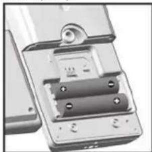
natural_image
Close-up of a metallic electronic device with battery pack and mounting holes (no visible text or symbols)natural_image
Diagram of a door switch with an arrow indicating direction (no text or symbols)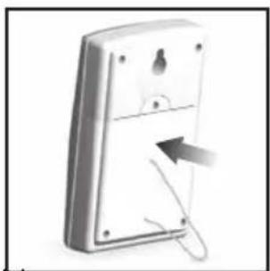
natural_image
3D rendering of a remote control panel with a paperclip and arrow indicating cable attachment (no text or symbols)P/N:086L004344-058 REV 141/94
text_image
1 2 3 4 5 25.8 56% 23.8 55% 13:26 10/28 4thP/N:086L004344-058 REV 1 50/94
text_image
1 2 3 4 5 6 7 8 9 10 MAX MIN HEAT INDEX MAX LO 108:00 88% 11natural_image
Close-up of a gray mechanical component with a white curved arrow on its side (no text or symbols visible)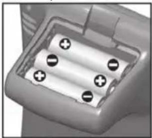
natural_image
Close-up of a battery pack with four white cylindrical cells and four black circular indicators (no text or symbols visible)
natural_image
Close-up of a hand using a tool to apply material to a component with mounting holes (no visible text or symbols)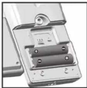
natural_image
Close-up of a mechanical device with two batteries and a lock (no visible text or symbols)natural_image
Diagram of a door switch with an arrow indicating left motion (no text or symbols)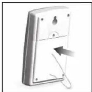
natural_image
Illustration of a remote control panel with a cable and arrow indicating cable attachment (no text or symbols)P/N:086L004344-058 REV 1 53/94
text_image
1 2 3 4 5 6 7 8 9 10 MAX MIN HEAT INDEX 108:00 MAX MIN 88% 11natural_image
Close-up of a gray mechanical component with a white curved arrow pointing downward (no text or symbols visible)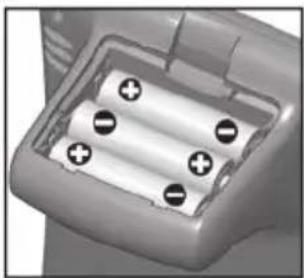
natural_image
Close-up of a battery pack with four black battery symbols on its side (no text or labels visible)natural_image
Close-up of a hand using a tool to apply material to a component with mounting holes (no visible text or symbols)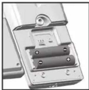
natural_image
Close-up of a mechanical device with two batteries and a lock (no visible text or symbols)natural_image
Diagram of a door switch with an arrow indicating left motion (no text or symbols)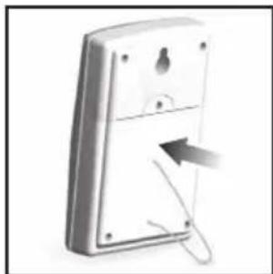
natural_image
Illustration of a remote control panel with a cable and arrow indicating cable attachment (no text or symbols)P/N:086L004344-058 REV 165/94
text_image
1 2 3 4 5 6 7 8 9 10 MAX MIN HEAT INDEX 108:00 MAX MIN 88% 11BUITENSENSOR (THGN122N)
text_image
Therap - Magic router 1natural_image
Close-up of a gray mechanical component with a white curved arrow on the top surface (no text or symbols visible)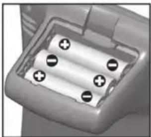
natural_image
Close-up of a battery pack with four black battery symbols on one side (no text or labels visible)
natural_image
Close-up of a hand using a tool to apply material to a component with mounting holes (no visible text or symbols)
natural_image
Close-up of a mechanical device with two batteries and a lock (no visible text or symbols)natural_image
Diagram of a door switch with an arrow indicating left motion (no text or symbols)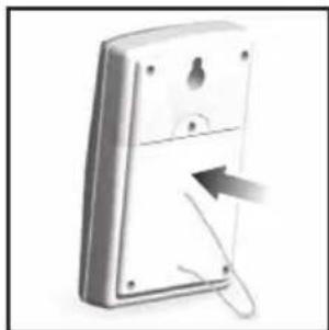
natural_image
Illustration of a remote control panel with a cable and arrow indicating cable attachment (no text or symbols)P/N:086L004344-058 REV 176/94
P/N:086L004344-058 REV 179/94
VORSTWAARSCHUWING
text_image
1 2 3 4 5 25.8 56% 23.8 55% 13:26 10/28 4thP/N:086L004344-058 REV 1 84/94
natural_image
Close-up of a gray mechanical component with a white arrow symbol pointing to a specific area (no text or labels visible)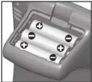
natural_image
Close-up of a battery pack with four black battery symbols and one white plus sign (no text or labels visible)
natural_image
Close-up of a hand using a tool to apply material to a component with mounting holes (no visible text or symbols)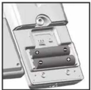
natural_image
Close-up of a metallic electronic device with battery and indicator lights (no visible text or symbols)natural_image
Simple line drawing of a door with an arrow indicating left motion (no text or symbols)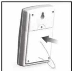
natural_image
Illustration of a remote control panel with a cable inserted, showing no text or symbols on the panel itself.P/N:086L004344-058 REV 1 87/94
För bästa resultat:
©2007 Oregon Scientific. All rights reserved.
086L004344-058