
EY7880 - Screwdriver PANASONIC - Free user manual and instructions
Find the device manual for free EY7880 PANASONIC in PDF.
| Product type | Cordless rotary hammer / hammer drill |
| Brand and model | Panasonic EY7880 |
| Motor voltage | 28.8 V DC |
| Battery | Li-ion 28.8 V / 3 Ah (model EY9L80) |
| Charger | Model EY0L80, 0.95 kg |
| No-load speed | Low speed: 0-500 rpm; High speed: 0-920 rpm |
| Impact frequency | Soft mode: 0-2800 bpm; Hard mode: 0-4500 bpm |
| Max. drilling diameter (concrete) | 20 mm |
| Max. drilling diameter (steel) | 13 mm |
| Max. drilling diameter (wood) | 27 mm |
| Weight (with battery) | 3.8 kg |
| Total length | 319 mm |
| Operating modes | Rotation + hammer (hard/soft), rotation only (high speed/low speed) |
| Chuck type | SDS-Plus for concrete drills; optional keyless chuck for wood/metal drills |
| Safety | Switch lock (center lever), overload and overdischarge protection, automatic shut-off in case of jamming |
| Maintenance and cleaning | Use a dry cloth, do not use solvents; lubricate the drill bit monthly |
| Included accessories | Side handle, depth gauge, wrist strap |
| Options | Keyless chuck (EY9HX400E), hammer chuck (EY9HX401E), drill chuck (EY9HX402E), dust collector (EY9X004E) |
| Charging temperature | Between 0°C and 40°C; automatic charging interrupted if battery is hot or too cold |
| Recycling | Battery and device must be disposed of at a collection point in accordance with European directives |
Frequently Asked Questions - EY7880 PANASONIC
User questions about EY7880 PANASONIC
0 question about this device. Answer the ones you know or ask your own.
Ask a new question about this device
Download the instructions for your Screwdriver in PDF format for free! Find your manual EY7880 - PANASONIC and take your electronic device back in hand. On this page are published all the documents necessary for the use of your device. EY7880 by PANASONIC.
USER MANUAL EY7880 PANASONIC
Cordless Rotary Hammer Akku-Bohrhammer
Marteau rotatif [sur batterie]
natural_image
Line drawing of a digital camera with control buttons and display panel (no text or symbols)Before operating this unit, please read these instructions completely and save this manual for future use. Vor Inbetriebnahme des Gerätes die Betriebsanleitung bitte gründlich durchlesen und diese Broschüre zum späteren Nachschlagen sorgfältig aufbewahren. Lire entièrement les instructions suivantes avant de faire fonctionner l'appareil et conserver ce mode d'emploi à des fins de consultation ultérieure. Prima di usare questo apparecchio, leggere completamente queste istruzioni e conservare il manuale per usi futuri. Lees deze gebruiksaanwijzing aandachtig door voor u het apparaat in gebruik neemt en bewaar de gebruiksaanwijzing voor eventuele naslag. Antes de usar este aparato por primera vez, lea todas las instrucciones de este manual y guarde el manual para poderlo consultar en el futuro. Gennemlæs denne betjeningsvejledning før brugen og gem den til fremtidig brug.
Läs igenom hela bruksanvisningen innan produkten tas i bruk. Spara bruksanvisningen för senare användning. Før enheten tas i bruk, vennligst les disse alle anvisningene og oppbevar bruksanvisningen for senere bruk. Lue ohjeet huolella ennen laitteen käyttöönottoa ja säilytä tämä käyttöohje tallessa tulevaa tarvetta varten.
* Chisel attachment (EY9HX402E) is an included accessory for European countries. For other countries, it is available instead as an Optional accessory.
| (A) | ChuckFutterMandrinMandrinoBoorkopPortabrocaBorepatronChuckChuckKiinnityslaiteЗажимной патронЗатискний патрон | (B) | Depth gaugeBohrtiefenanschlagJauge de profondeurCalibro di profonditàDieptemeterCalibre de profundidadDybdemålerDjupmätareDybdemålerSyvyysmittariГлубиномерГлибиномір |
| (C) | Hammering/drilling switching leverZum Umschalten zwischen normalem Bohren und SchlagbohrenCommutateur martelage/perforationLeva di commutazione martellatura/perforazioneKeuzehendel normaal boren/klopborenPalanca de conmutación de martillo/taladroHarrings/borings omskiftningsgrebOmkopplare mellan slagborr/vanlig borrSlag/bor omskifterVasaran/poran kytkentävipuРычаг переключения долбления/сверленияВажіль перемикання довбання/свердління | (D) | Speed/Blow Mode selection leverGeschwindigkeit/Schlag stärke ModuswahlhebelLevier de sélection de vitesse/mode de souffi erieLeva di selezione velocità colpoSnelheid/klopfunctie-keuzehendelPalanca del selector de velocidad/modo de sopladorHastighedsvælger/BlæserfunktionsvælgerVäljare för hastighet/slaglägeVelger for hastighet/blåsingNopeuden/iskumuodon valintavipuРычаг выбора скорости/удараВажіль вибору швидкості/удару |
| (E) | Forward/Reverse leverRechts/Linkslauf SchalterLevier d'inversion marche avant-marche arrièreLeva di avanzamento/inversioneVoorwaarts/achterwaarts-hendelPalanca de avance/inversiónGreb til forlæns/baglæns retningRiktningsomkopplareForover/Revers bryterEteenpäin/taaksepäin vipuРычаг переключения вперед/назадВажіль перемикання вперед/назад | (F) | Variable speed control triggerBetriebsschalterGâchette de commande de vitesseGrilletto di controllo velocità variableStartschakelaar variabele snelheidDisparador del control de velocided variableKontroludlöser for variabel hastighedSteglös varvtalsreglerareHovedbryter, trinnlösNopeudensäätökytkinПереключатель регулировки переменной скоростиПеремикач регулювання змінної швидкості |
| (G) | Battery holderBatterie HalterSupport de la batterieCustodia della batteriaAccuhouderSoporte de la bateríaBatteriholderBatterihållareBatteriholderAkun pidinyksikköДержатель аккумулятораТримач аккумулятора | (H) | Alignment marksAusrichtmarkierungenMarques d'alignementMarcature allineamentoUitlijntekensMarcas de alineaciónFlugtemærkerAnpassningsmärkenOpprettingsmerkeSovitusmerkitМетки совмещенияМітки вирівнювання |
| (I) | Battery pack (EY9L80)Akku (EY9L80)Batterie autonome (EY9L80)Pacco batteria (EY9L80)Accu (EY9L80)Batería (EY9L80)Batteripakning (EY9L80)Batteri (EY9L80)Batteripakke (EY9L80)Akku (EY9L80)Батарейный блок (EY9L80)Батарейний блок (EY9L80) | (J) | Control panelBedienfeldPanneau de commandePannello di controlloBedieningspaneelPanel de controleKontrolpanelKontrollpanelKontrollpanelSäätöpaneeliПанель управленияПанель управління |
| (K) | LED light on/off buttonLED-Leuchten-EIN/AUS-TasteBouton Marche/Arrêt de la lumière DELTasto di accensione e spegnimento della luce LEDAan/uit-toets (ON/OFF) voor LED-lampjeBotón ON/OFF de luz LDETAEND/SLUK-knap til LED-lysStrömbrytare för LED-IjusPA/AV-knapp for LED-lysLED-valon kytkin/katkaisupainikeКнопка включения/выключения светодиодной подсветкиКнопка ввімкнення/вимкнення світлодіодного підсвічування | (L) | Overheat warning lamp (motor/battery)Überhitzungs-Warnlampe (Motor/Akku)Témoin d'avertissement de surchauffe (moteur/batterie)Spia avvertenza surriscaldamento (motore/batteria)Oververhitting-waarschuwingslampje (motor/accu)Luz de advertencia de sobrecalentamiento (motor/batería)Advarselslamp til overophedning (motor/batteri)Varningslampa för överhettning (motor/batteri)Varsellampe for overoppheiting (motor/batteri)Ylikuumenemisen varoituslamppu (moottori/akku)Предупреждающая лампочка перегрева (мотор/батареи)Попереджувальна лампочка перегріву (мотор/батареі) |
| (M) | Battery low warning lampAkkuladungs-WarnlampeTémoin d'avertissement de batterie basseSpia avvertenza batteria scaricaWaarschuwingslampje voor lage accuspanningLuz de aviso de baja carga de bateríaAdvarselslampes batterieffekt lavVarningslampa för svagt batteriVarsellampe for at batteriet er for lavtAlhaisen akkujännitteen varoituslamppuПредупреждающая лампочка низкого заряда батареиПопереджувальна лампочка низького заряду батареї | (N) | Battery pack release buttonAkku-EntriegelungsknopfBouton de libération de batterie autonomeTasto di rilascio pacco batteriaAccu-ontgrendeltoetsBotón de liberación de bateríaUdløserknap til batteripakningFrigöringsknapp för batteriUtløserknapp for batteripakkeAkkupaketin irrotuspainikeКнопка освобождения батарейного блокаКнопка вивільнення батарейного блоку |
| (O) | Support handleZusatzgriffManche de supportManiglia di sostegnoSteungreepMango de soporteHjælpehåndtagStödhandtagStøttehåndtakTukikahvaПоддерживающая рукояткаПідтримуюча рукоятка | (P) | LED lightLED-LeuchteLumière DELLuce LEDLED-lampjeLuz indicadoraLED-lysLED-ljusLED-lysLED-valoСветодиодная подсветкаСвітлодіодне підсвічування |
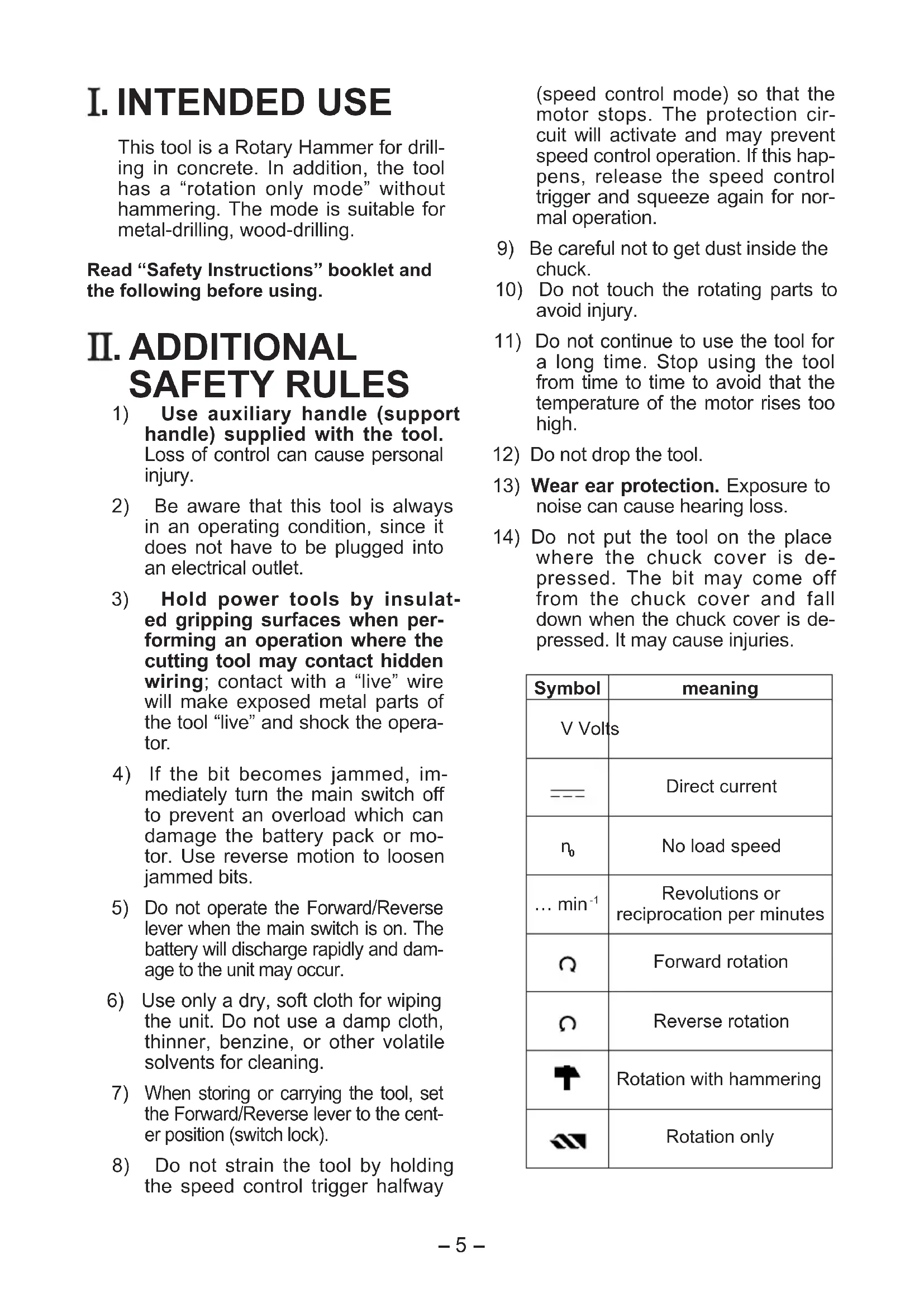
| (Q) | Li-ion battery pack dockLi-Ion-AkkuladeschachtPoste d'accueil de la batterie autonome Li-ionSpazio raccordo pacco batteria Li-ionLi-ion accuhouderEnchufe de carga de batería Li-iónLi-ion batteripakningsdokDocka för litiumjonbatteriDokk for Li-ion-batteripakkeLi-ioniakun liitinУглубление для установки литий-ионного батарейного блокаЗаглиблення для встановлення літій-іонного батарейного блоку | (R) | Battery charger (EY0L80)Ladegerät (EY0L80)Chargeur de batterie (EY0L80)Caricabatterie (EY0L80)Acculader (EY0L80)Cargador de batería (EY0L80)Batterioplader (EY0L80)Batteriladdare (EY0L80)Batterilader (EY0L80)Akkulaturi (EY0L80)Зарядное устройство (EY0L80)Зарядний пристрій (EY0L80) |
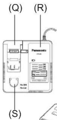
| (S) | Ni-MH/Ni-Cd battery pack dockNi-MH/Ni-Cd-AkkuladeschachtPoste d'accueil de la batterie autonome Ni-MH/Ni-CdSpazio raccordo pacco batteria Ni-MH/Ni-CdNi-MH/Ni-Cd accuhouderEnchufe de carga de batería Ni-MH/Ni-CdNi-MH/Ni-Cd batteripakningsdokDocka för NiMH/NiCd-batteriDokk for Ni-MH/Ni-Cd-batteripakkeNi-MH/Ni-Cd akun liitinУглубление для установки никель-металлогидридногобатарейного блока/никель-кадмиевого батарейного блокаЗаглиблення для встановлення нікель-метал-гідридногобатарейного блоку/нікель-кадмієвого батарейного блоку | (T) | Pack coverAkkuabdeckungCouvercle de la batterie autonomeCoperchio paccoAccudekselCubierta de bateríaPakningsdækselBatteriskyddPakkedekselAkkukotelon kansiКрышка блокаКришка блоку |
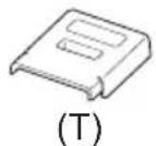
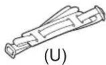
| (U) | Shoulder strapSchulterriemenDragonneCinghia da spallaSchouderriemCorrea al hombroSkulderremAxelremSkulderbelteOlkahihnaПлечевой ременьПлечовий ремінь | (V) | GreaseSchmierfettGraisseLubrifi canteVetGrasaSmørefedtFettSmørefettRasvaСмазкаМастило |
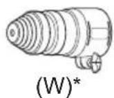
| (W) | Chisel Attachment (EY9HX402E, will be included with shipment according to the destination)Meißelvorsatz (EY9HX402E, wird je nach Zielort mitgeliefert)Fixation pour burin (EY9HX402E, sera inclus dans la livraison en fonction de la destination)Accessorio per cisellatura (EY9HX402E, sarà accluso agli articoli consegnati a seconda della destinazione)Beitelhulpstuk (EY9HX402E, wordt afhankelijk van de bestemming meegeleverd)Punzón accesorio (EY9HX402E, incluido en el envío dependiendo del destino)Mejseltilbehørsdel (EY9HX402E vil medfølge ved afsendelsen alt efter destinationen)Mejseltillsats (EY9HX402E, medföljer leveransen beroende på destination)Tilbehør for meisling (EY9HX402E, vedlegges frakten i henhold til ankomstdestinasjon)Talttaliitin (EY9HX402E, sisältyy toimitukseen kohteen mukaan)Долотчатая насадка (EY9HX402E, включается в поставку в соответствии с назначением)Долотчаста насадка (EY9HX402E, входить до комплекту відповідно до призначення) | ||
I. INTENDED USE
This tool is a Rotary Hammer for drilling in concrete. In addition, the tool has a “rotation only mode” without hammering. The mode is suitable for metal-drilling, wood-drilling.
Read "Safety Instructions" booklet and the following before using.
II. ADDITIONAL SAFETY RULES
1) Use auxiliary handle (support handle) supplied with the tool. Loss of control can cause personal injury.
2) Be aware that this tool is always in an operating condition, since it does not have to be plugged into an electrical outlet.
3) Hold power tools by insulated gripping surfaces when performing an operation where the cutting tool may contact hidden wiring; contact with a "live" wire will make exposed metal parts of the tool "live" and shock the operator.
4) If the bit becomes jammed, immediately turn the main switch off to prevent an overload which can damage the battery pack or motor. Use reverse motion to loosen jammed bits.
5) Do not operate the Forward/Reverse lever when the main switch is on. The battery will discharge rapidly and damage to the unit may occur.
6) Use only a dry, soft cloth for wiping the unit. Do not use a damp cloth, thinner, benzine, or other volatile solvents for cleaning.
7) When storing or carrying the tool, set the Forward/Reverse lever to the center position (switch lock).
8) Do not strain the tool by holding the speed control trigger halfway
(speed control mode) so that the motor stops. The protection circuit will activate and may prevent speed control operation. If this happens, release the speed control trigger and squeeze again for normal operation.
9) Be careful not to get dust inside the chuck.
10) Do not touch the rotating parts to avoid injury.
11) Do not continue to use the tool for a long time. Stop using the tool from time to time to avoid that the temperature of the motor rises too high.
12) Do not drop the tool.
13) Wear ear protection. Exposure to noise can cause hearing loss.
14) Do not put the tool on the place where the chuck cover is depressed. The bit may come off from the chuck cover and fall down when the chuck cover is depressed. It may cause injuries.
| Symbol | meaning |
| V Volts | |
| --- | Direct current |
| n_0 | No load speed |
| ... min-1 | Revolutions orreciprocation per minutes |
| Ω | Forward rotation |
| Ω | Reverse rotation |
| ↑ | Rotation with hammering |
| ↔ | Rotation only |

WARNING:
- Do not use other than the Panasonic battery packs that are designed for use with this rechargeable tool.
- Do not dispose of the battery pack in a fire, or expose it to excessive heat.
- Do not drive the likes of nails into the battery pack, subject it to shocks, dismantle it, or attempt to modify it.
- Do not allow metal objects to touch the battery pack terminals.
- Do not carry or store the battery pack in the same container as nails or similar metal objects.
- Do not charge the battery pack in a high-temperature location, such as next to a fire or in direct sunlight. Otherwise, the battery may overheat, catch fire, or explode.
- Never use other than the dedicated charger to charge the battery pack. Otherwise, the battery may leak, overheat, or explode.
• After removing the battery pack from the tool or the charger, always reattach the pack cover. Otherwise, the battery contacts could be shorted, leading to a risk of fire.
III. ASSEMBLY
Attaching or Removing Bit Chuck
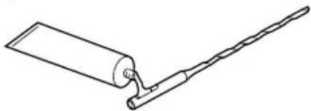
NOTE: Grease for bit
Grease the oval indentation on the bit with the supplied grease at least once a month.
natural_image
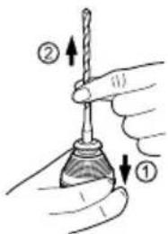
Line drawing of a tool with a cylindrical component and a zigzag handle (no text or symbols)1. To mount the bit
1-1. Insert a bit into the mounting hole, and turn it slightly to locate an engaged position.
1-2. At the engaged position, push the bit as far as it goes. Make sure that the bit is fixed by pulling it.
2. To dismount the bit
2-1. Depress the chuck cover and pull the bit.
Attaching or Removing Battery pack
Battery holder
The battery pack is designed to be installed by proceeding two steps for safety. Make sure the battery pack is installed properly to the main body before use.
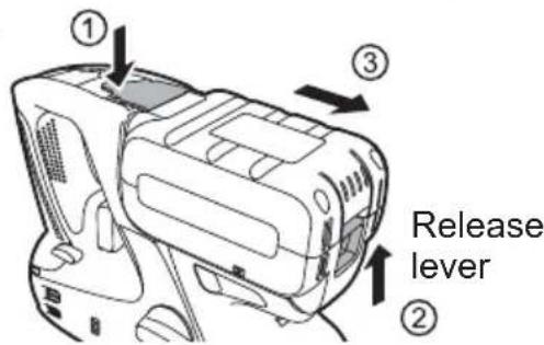
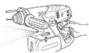
- Battery pack Installation and Removal -For removal-
Push the battery holder (①)
While the battery pack release button is held up, (②) move the battery pack laterally and pull out the pack. (③)
Battery holder
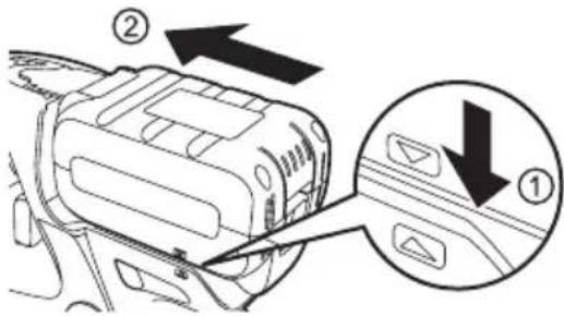
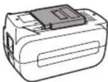
-For installation-
To attach the battery pack, line up the alignment marks on the body of the tool and the battery pack, (①) and insert the battery pack. (②)
• After you hear the battery pack clicks when inserting it, keep inserting it firmly until the lever locks it to click once more.
NOTE:
- The overheat warning lamp and the battery low warning lamp will flash when the battery pack is not inserted firmly.
IV. OPERATION
[Main Body]
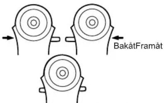
Forward/Reverse lever
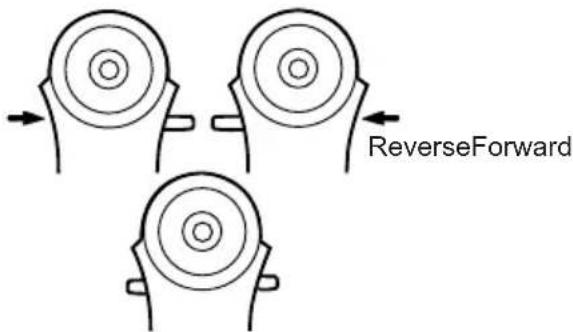
- Be sure to set the switch in the center to lock it after use.
- Operate the Forward/Reverse lever after the motor rotation is completely stopped.
Hammering/drilling switching lever/Speed/Blow Mode selection lever
- There are four modes available with the combination of Hammering/ drilling switching lever and Speed/Blow Mode selection lever. Select the suitable mode for application.
- Operate the mode change after the motor rotation is completely stopped.
| Position of switching lever | Speed/Blow Mode selection lever | Recommended application |
 (Rotation with hammering) (Rotation with hammering) | Hard blow hammer-ing mode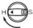 | This mode has hard blow hammering which is suitable for concrete drilling.• Concrete drill |
Soft blow hammering mode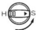 | This mode is suitable for concrete drilling with smaller diameter drill, or for drilling into soft base material.• Small diameter concrete drill | |
 (Rotation only) (Rotation only) | High speed drilling mode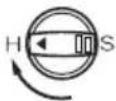 | This mode is suitable for metal drilling with high speed rotation.• Metal drill• Metal hole saw |
Slow speed drilling mode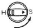 | This mode is suitable for wood drill with high torque.• Wood drill |
(Rotation only)
Variable speed control trigger
To set the center of a hole, pull the trigger slightly to start the drill rotation slowly.
Support handle
Place the support handle at your favorite position and tighten the handle securely.

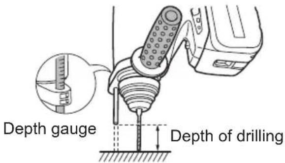
Depth gauge
Loosen the support handle and adjust the depth gauge at your favorite depth. After adjusting, tighten the support handle and fix depth gauge.
Installing the Shoulder Strap
CAUTION:
• Install the shoulder strap firmly to the main unit of the tool and check the length of the strap before use.
- Check the condition of the strap and do not use if it is cut or torn etc. There is a risk of injury or damage if used while improperly installed.
- Please wear the shoulder strap securely on the shoulder.
There is a risk of injury or damage if it is accidentally dropped.
-
Pass the strap through the strap holders.
-
Pass the strap through the buckles and adjust the length.
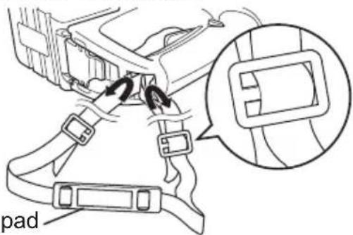
Shoulder pad
Follow the instructions below in order to avoid injury.
- The shoulder strap can be adjusted according to the individual.
- Adjust the shoulder pad to the shoulder.
- Pull the shoulder strap to make sure it is firmly attached to the main unit of the tool.
Control panel
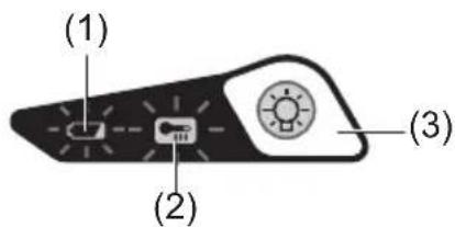
(1) Battery low warning lamp
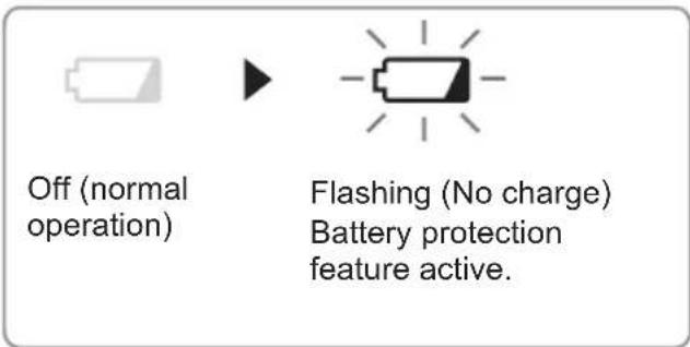
Excessive (complete) discharging of Li-ion batteries shortens their service life dramatically. The driver includes a battery protection feature designed to prevent excessive discharging of the battery pack.
- The battery protection feature activates immediately before the battery loses its charge, causing the battery low warning lamp to flash.
- If you notice the battery low warning lamp flashing, charge the battery pack immediately.
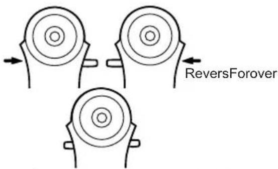
(2) Overheat warning lamp
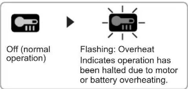
The overheating protection feature halts driver operation to protect the motor and battery pack in the event of overheating. The overheat warning lamp on the control panel flashes when this feature is active.
- If the overheating protection feature activates, allow the driver to cool thoroughly (at least 30 minutes). The driver is ready for use when the overheat warning lamp goes out.
- Avoid using the driver in a way that causes the overheating protection feature to activate repeatedly.
NOTE:
- In summer or in other situations where the temperature is high, the overheating protection feature may activate and prevent continual use.
(3) LED light
natural_image
Line drawing of a handheld electric drill press with visible blades and control buttons (no text or symbols)Before the use of LED light, always pull the power switch once.
Press the LED light on button.
The light illuminates with very low current, and it does not adversely affect the performance of the tool during use or its battery capacity.
CAUTION:
- The built-in LED light is designed to illuminate the small work area temporarily.
- Do not use it as a substitute for a regular flashlight, since it does not have enough brightness.
• LED light turns off when the tool has not been used for 5 minutes.
Caution : DO NOT STARE INTO BEAM. Use of controls or adjustments or performance of procedures other than those specified herein may result in hazardous radiation exposure.
Battery pack
For Appropriate Use of Battery Pack
Li-ion Battery Pack (EY9L80)
- For optimum battery life, store the Li-ion battery pack following use without charging it.
- When battery pack is not in use, keep it away from other metal objects like: paper clips, coins, keys, nails, screws, or other small metal objects that can make a connection from one terminal to another.
Shorting the battery terminals together may cause sparks, burns or a fire. - When operating the battery pack, make sure the work place is well ventilated.
- When the battery pack is removed from the main body of the tool, replace the battery pack cover immediately in order to prevent dust or dirt from contaminating the battery terminals and causing a short circuit.
Battery Pack Life
The rechargeable batteries have a limited life. If the operation time becomes extremely short after recharging, replace the battery pack with a new one.
Battery Recycling
ATTENTION:
For environmental protection and recycling of materials, be sure that it is disposed of at an officially assigned location, if there is one in your country.
Battery charger
Charging
Cautions for the Li-ion Battery Pack
• Make sure the terminals of the battery charger are not contaminated with liquid, grease or other substances before charging the battery pack.
If you notice the terminals of the battery charger contaminated, be sure to wipe or take them off before use. The life of the battery pack may adversely be affected when the terminals are clogged with the dust or dirt which becomes solid with liquid or grease.
- If the temperature of the battery pack falls approximately below -10°C (14°F), charging will automatically stop to prevent degradation of battery.
Common Cautions for the Li-ion/Ni-MH/Ni-Cd Battery Pack
- The ambient temperature range is between 0°C (32°F) and 40°C (104°F). If the battery pack is used when the battery temperature is below 0°C (32°F), the tool may fail to function properly.
- When charging a cool battery pack (below 0°C (32°F)) in a warm place, leave the battery pack at the place and wait for more than one hour to warm up the battery to the
level of the ambient temperature.
- Cool down the charger when charging more than two battery packs consecutively.
- Do not insert your fingers into contact hole, when holding charger or any other occasions.
CAUTION:
To prevent the risk of fire or damage to the battery charger.
- Do not use power source from an engine generator.
- Do not cover vent holes on the charger and the battery pack.
- Unplug the charger when not in use.
Li-ion Battery Pack
NOTE:
Your battery pack is not fully charged at the time of purchase. Be sure to charge the battery before use.
Battery charger (EY0L80)
- Plug the charger into the AC outlet.
NOTE:
Sparks may be produced when the plug is inserted into the AC power supply, but this is not a problem in terms of safety.
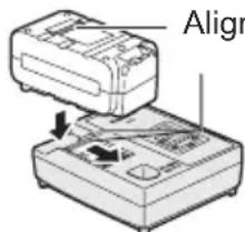
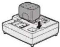
- Insert the battery pack firmly into the charger.
1 Line up the alignment marks and place the battery onto the dock on the charger.
2 Slide forward in the direction of the arrow.
- During charging, the charging lamp will be lit.
When charging is completed, an internal electronic switch will automatically be triggered to prevent overcharging.
- Charging will not start if the battery pack is warm (for example, immediately after heavy-duty operation).
The orange standby lamp will be flashing until the battery cools down. Charging will then begin automatically.
- The charge lamp (green) will flash slowly once the battery is approximately 80% charged.
- When charging is completed, the charging lamp will start flashing quickly in green color.
- If the temperature of the battery pack is 0^ C ( 32^ F) or less, charging takes longer to fully charge the battery pack than the standard charging time. Even when the battery is fully charged, it will have approximately 50% of the power of a fully charged battery at normal operating temperature.
- If the power lamp does not light immediately after the charger is plugged in, or if after the standard charging time the charging lamp does not flash quickly in green, consult an authorized service center.
- If a fully charged battery pack is inserted into the charger again, the charging lamp lights up. After several minutes, the charging lamp may flash quickly to indicate the charging is completed.
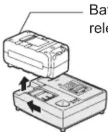
Battery pack release button
- Remove the battery pack while the battery pack release button is held up.
Ni-MH/Ni-Cd Battery Pack
NOTE:
When you charge the battery pack for the first time, or after prolonged storage, charge it for about 24 hours to bring the battery up to full capacity.
Battery charger (EY0L80)
- Plug the charger into the AC outlet.
NOTE:
Sparks may be produced when the plug is inserted into the AC power supply, but this is not a problem in terms of safety.
- Insert the battery pack firmly into the charger.
- During charging, the charging lamp will be lit. When charging is completed, an internal electronic switch will automatically be triggered to prevent overcharging.
- Charging will not start if the battery pack is warm (for example, immediately after heavy-duty operation). The orange standby lamp will be flashing until the battery cools down. Charging will then begin automatically.
-
When charging is completed, the charging lamp will start flashing quickly in green color.
-
If the charging lamp does not light immediately after the charger is plugged in, or if after the standard charging time the charging lamp does not flash quickly in green, consult an authorized service center.
-
If a fully charged battery pack is inserted into the charger again, the charging lamp lights up. After several minutes, the charging lamp may flash quickly to indicate the charging is completed.
LAMP INDICATIONS


Green Lit
Charger is plugged into the AC outlet.
Ready to charge.
Green Flashing Quickly
Charging is completed. (Full charge.)
Green Flashing
Battery is approximately 80% charged (Usable charge. Li-ion only).
Green Lit
Now charging.
Orange Lit
Battery pack is cool.
The battery pack is being charged slowly to reduce the load on the battery. (Li-ion only)
Orange Flashing
Battery pack is warm. Charging will begin when temperature of battery pack drops.
If the temperature of the battery pack is -10^ ( 14^ ) or less, the charging status lamp (orange) will also start flashing.
Charging will begin when the temperature of the battery pack goes up (Li-ion only).
Charging Status Lamp
Left: green Right: orange will be displayed.
Both Orange and Green Flashing Quickly
Charging is not possible. Clogged with dust or malfunction of the battery pack.
Information for Users on Collection and Disposal of Old Equipment and used Batteries
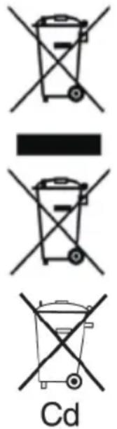
These symbols on the products, packaging, and/or accompanying documents mean that used electrical and electronic products and batteries should not be mixed with general household waste.
For proper treatment, recovery and recycling of old products and used batteries, please take them to applicable collection points, in accordance with your national legislation and the Directives 2002/96/EC and 2006/66/EC.
By disposing of these products and batteries correctly, you will help to save valuable resources and prevent any potential negative effects on human health and the environment which could otherwise arise from inappropriate waste handling.
For more information about collection and recycling of old products and batteries, please contact your local municipality, your waste disposal service or the point of sale where you purchased the items.
Penalties may be applicable for incorrect disposal of this waste, in accordance with national legislation.
For business users in the European Union
If you wish to discard electrical and electronic equipment, please contact your dealer or supplier for further information.
[Information on Disposal in other Countries outside the European Union]
These symbols are only valid in the European Union. If you wish to discard these items, please contact your local authorities or dealer and ask for the correct method of disposal.
Note for the battery symbol (bottom two symbol examples):
This symbol might be used in combination with a chemical symbol. In this case it complies with the requirement set by the Directive for the chemical involved.
Chisel Attachment (EY9HX402E) (will be included with shipment according to the destination)
CAUTION:
- The Chisel attachment is intended to be used with Rotary hammer EY7880. When used on another tool, it may create a risk of injury.
- Disconnect Battery pack from tool or place the switch in the locked off position before attach or remove the Chisel attachment. Such preventive safety measures reduce the risk of starting the tool accidentally.
- Apply the lubricant grease on the shaft in the Chisel attachment before use.
- The Chisel attachment creates heat. It may become very hot and may cause skin burns.
Do not operate the Chisel attachment more than 30 minutes continuously.
- To reduce the risk of injury, use the Support handle on the Rotary hammer.
- Replace the Chisel attachment immediately when the Dust protect rubber cap is broken to avoid the dust coming inside the attachment.
Usage:
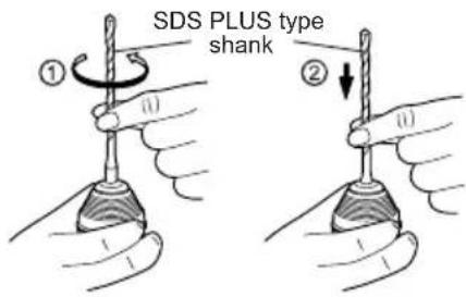
- Use with a Chisel bit with SDS-Plus type shank in Rotation+Hammer mode, for Light duty chiseling (ceramic tile remove, scraping sealing material etc.)
- To attach the Chisel attachment Remove the Support handle from the Rotary hammer. Mount the Chisel attachment on the tool. Make sure to eliminate a play between the attachment and tool. Fix the attachment firmly on the tool using the butterfly screw.
- Attach the Support handle on the Chisel attachment.
- Insert/detach the Chisel bit Read instruction manual of the Rotary hammer.
- To adjust the blade angle of the Chisel bit
Rotate the Chisel attachment to adjust the blade angle of Chisel bit for better setting.
Dust Collection Cup (EY9X004E) (Available as an optional accessory)
* Drill bits of which diameter is 20 mm above cannot be inserted through dust collection cup.
* Do not use the tool for cutting other than concrete, mortar and other ceramic materials. If used for cutting metal materials, the dust collection cup may be damaged by the metal chip heat.
- Install a drill bit.
- Pass the drill bit through A and fix the cup at B by matching with the shape of the support handle.
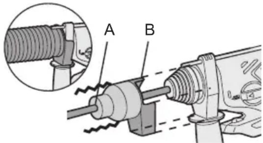
Operation
Keep the dust collection cup in close contact with the wall surface during operation.
natural_image
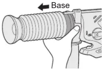
Technical line drawing of a threaded bolt assembly (no text or symbols)Removal
Hold the base of the dust collection cup for removal.
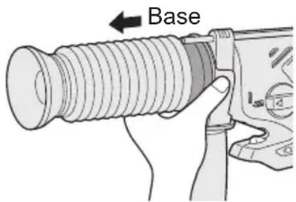
Please remove after thoroughly getting rid of the dust in the dust collection cup.
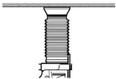
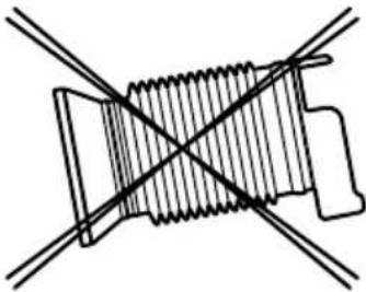
Storage
Do not store the dust collection cup in a compressed position. If kept in a compressed position, it may be impossible to return to the original shape.
natural_image
Pure mechanical cross-section diagram without any text, numbers, or symbolsV. MAINTENANCE
Use only a dry, soft cloth for wiping the unit. Do not use a damp cloth, thinner, benzine, or other volatile solvents for cleaning.
VI. ACCESSORIES
CAUTION:
To prevent the risk of injury, only use accessory or attachment for its stated purpose.
Dust Collection Cup
•EY9X004E
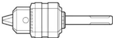
Drill chuck
•EY9HX400E
natural_image
Technical line drawing of a mechanical tool or drill bit (no text or symbols)Use with wood drill bit or metal drill bit with shank of 1.5 mm to 13 mm diameter.
Do not use the drill chuck in "Rotation with hammering mode (↑)". Use in "Rotation with hammering mode" may cause break of bit and result in injury.
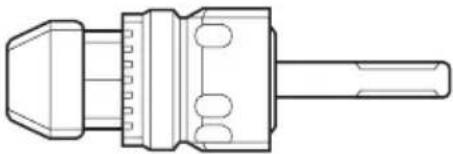
Hammer chuck
•EY9HX401E
natural_image
Technical line drawing of a mechanical connector or tool (no text or symbols)Use with concrete drill bit, wood drill bit or metal drill bit with straight shank of 2.5 mm to 13 mm diameter.
Do not use the hammer chuck with wood drill bit or metal drill bit in "Rotation with hammering mode" ( ↑ ). Use in "Rotation with hammering mode" may cause break of bit and result in injury.
Chisel Attachment
•EY9HX402E
If you need any assistance for more details regarding these accessories, ask your local service center.
VII. USAGE SUGGESTION
- If there isn't enough force pushing down on the bit, the hammer may not be able to blow in hammering mode.
This is to prevent the hammering mode from operating with no load. Press down harder on the bit to engage the hammer and cause it to blow.
Always be sure to press down with enough force when working.
- In winter or in other situations where the temperature of the unit is low (5°C or below), the blow of the hammering mode may be weaker than normal at the beginning stage.
This is because the grease becomes stiffer in low temperatures, increasing friction.
If this should happen, operating hammering mode with no load for approximately 30 seconds and repeat this 3 times. This will restore its blowing power.
VIII. SPECIFICATIONS
MAIN UNIT
| Maximum Drilling Diameter | Concrete 20 mm (25/32") | |
| Steel 13 mm (33/64") | ||
| Wood 27 mm (1-1/16") | ||
| Motor Voltage 28.8 V DC | ||
| Speed At No Load (RPM) | Slow Mode 0 | -500 min ^-1 (rpm) |
| High Mode | 0 - 920 min ^-1 (rpm) | |
| Blows Rate Per Minute (BPM) | Soft Mode | 0 - 2800 min ^-1 (bpm) |
| Hard Mode 0 | -4500 min ^-1 (bpm) | |
| Weight (with battery pack) | 3.8 kg (8.4 lbs) | |
| Overall length 319 mm (12 | -9/16") | |
| Noise, Vibration | See the included sheet | |
BATTERY PACK
| Model | EY9L80 |
| Storage battery | Li-ion Battery |
| Battery voltage | 28.8 V DC (3.6 V x 8 cells) |
| Capacity | 3 Ah |
BATTERY CHARGER
| Model EY0L80 | |
| Rating See the rating plate on the bottom of the charger. | |
| Weight 0.95 kg | (2.1 lbs) |
[Li-ion battery pack]
| Charging time 3 | Ah | 14.4 V 28.8 V | |
| EY9L40 | EY9L80 | ||
| Usable: 35 min. | Usable: 55 min. | ||
| Full: 50 min. | Full: 70 min. |
[Ni-Cd/Ni-MH battery pack]
| Charging time | 7.2 V 9.6 | V 12 V 15.6 | V 18 V 24 V | ||||
| 1.2 Ah | EY9065 | EY9080 | EY9001 | ||||
| EY9066 | EY9086 | EY9006 | |||||
| 20 min. | |||||||
| 1.7 Ah | EY9180 | EY9101 | |||||
| EY9182 | EY9103 | ||||||
| 25 min. | |||||||
| 2 Ah | EY9168 E | Y9188 | EY9106 | EY9136 | EY9116 | ||
| EY9107 | EY9117 | ||||||
| 30 min. | 60 min. | ||||||
| 3 Ah | EY9200 E | Y9230 EY9210 | |||||
| 45 min. 90 min. | |||||||
| 3.5 Ah | EY9201 E | Y9231 EY9251 | |||||
| 55 min. 65 min. | |||||||
NOTE: This chart may include models that are not available in your area. Please refer to the latest general catalogue.
NOTE: For the dealer name and address, please see the included warranty card.
ONLY FOR U. K.
IX. ELECTRICAL PLUG INFORMATION
FOR YOUR SAFETY PLEASE READ THE FOLLOWING TEXT CAREFULLY
This appliance is supplied with a moulded three pin mains plug for your safety and convenience.
A 5 amp fuse is fitted in this plug.
Should the fuse need to be replaced please ensure that the replacement fuse has a rating of 5 amp and that it is approved by ASTA or BSI to BS1362.
Check for the ASTA mark 🎨 or the BSI mark 🌐 on the body of the fuse.
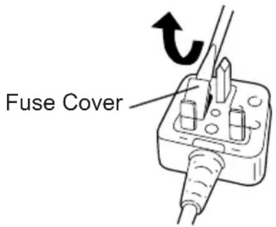
If the plug contains a removable fuse cover you must ensure that it is refi tted when the fuse is replaced.
If you lose the fuse cover the plug must not be used until a replacement cover is obtained.
A replacement fuse cover can be purchased from your local Panasonic Dealer.
IF THE FITTED MOULDED PLUG IS UNSUITABLE FOR THE SOCKET OUTLET IN YOUR HOME THEN THE FUSE SHOULD BE REMOVED AND THE PLUG CUT OFF AND DISPOSED OF SAFELY.
THERE IS A DANGER OF SEVERE ELECTRICAL SHOCK IF THE CUT OFF PLUG IS INSERTED INTO ANY 13 AMP SOCKET.
If a new plug is to be fitted please observe the wiring code as shown below.
If in any doubt please consult a qualified electrician.
IMPORTANT: The wires in this mains lead are coloured in accordance with the following code: Blue: Neutral Brown: Live
As the colours of the wire in the mains lead of this appliance may not correspond with the coloured markings identifying the terminals in your plug, proceed as follows.
The wire which is coloured BLUE must be connected to the terminal in the plug which is marked with the letter N or coloured BLACK.
The wire which is coloured BROWN must be connected to the terminal in the plug which is marked with the letter L or coloured RED.
Under no circumstances should either of these wires be connected to the earth terminal of the three pin plug, marked with the letter E or the Earth Symbol 12 .
How to replace the fuse: Open the fuse compartment with a screwdriver and replace the fuse and fuse cover if it is removable.
This apparatus was produced to BS800.
natural_image
Line drawing of a mechanical tool or tool with a cylindrical component and a zigzag handle (no text or symbols)IV. BEDIENUNG
[Maschine]
natural_image
Line drawing of a handheld electric drill press with visible components and wiring (no text or symbols)natural_image
Technical line drawing of a threaded bolt assembly (no text or symbols)Ausbau
natural_image
Pure mechanical cross-section diagram without any text, numbers, or symbolsV. WARTUNG
natural_image
Technical line drawing of a mechanical tool or drill bit (no text or symbols)Aufnahmekapazität:
natural_image
Technical line drawing of a mechanical component with no visible text or symbolsnatural_image
Line drawing of a mechanical tool or tool with a cylindrical component and a straight rod (no text or symbols)IV. UTILISATION
[Corps principal]
natural_image
Line drawing of a handheld electric drill with tool handle and base (no text or symbols)Utilisation
natural_image
Technical line drawing of a threaded bolt assembly (no text or symbols)Retrait
natural_image
Pure mechanical diagram showing a spring with intersecting lines, no text or symbols presentV. ENTRETIEN
natural_image
Technical line drawing of a mechanical tool with hexagonal base and cylindrical shaft (no text or symbols)natural_image
Technical line drawing of a mechanical connector or connector (no text or symbols)natural_image
Line drawing of a mechanical tool or tool with a cylindrical component and a straight rod (no text or symbols)IV. FUNZIONAMENTO
[Corpo principale]
natural_image
Line drawing of a handheld electric drill press with handle and control panel (no text or symbols)natural_image
Technical line drawing of a threaded bolt assembly (no text or symbols)Rimozione
natural_image
Pure mechanical cross-section diagram without any text, numbers, or symbolsV. MANUTENZIONE
natural_image
Technical line drawing of a mechanical drill bit (no text or symbols)natural_image
Technical line drawing of a mechanical connector or connector (no text or symbols)natural_image
Line drawing of a mechanical tool or tool with a cylindrical component and a straight rod (no text or symbols)1. Bevestigen van de bit
IV. GEBRUIK
[Gereedschap]
natural_image
Line drawing of a handheld electric drill with visible tool handle and wiring (no text or symbols)Bediening
natural_image
Technical line drawing of a threaded fastener assembly (no text or symbols)Legen
natural_image
Pure mechanical diagram showing a spring-loaded component intersected by two diagonal lines (no text or symbols)V. ONDERHOUD
natural_image
Technical line drawing of a mechanical tool or drill bit (no text or symbols)natural_image
Technical line drawing of a mechanical component with no visible text or symbolsnatural_image
Line drawing of a mechanical tool with a cylindrical component and a straight rod (no text or symbols)1. Para montar la broca
IV. FUNCIONAMIENTO
natural_image
Line drawing of a handheld electric drill with visible tool handle and base (no text or symbols)natural_image
Technical line drawing of a threaded bolt assembly (no text or symbols)Traslado
natural_image
Pure mechanical diagram showing a spring-loaded component intersected by two diagonal lines (no text or symbols)V. MANTENIMIENTO
natural_image
Technical line drawing of a mechanical tool or drill bit (no text or symbols)natural_image
Technical line drawing of a mechanical connector or connector (no text or symbols)natural_image
Simple line drawing of a cylindrical object connected to a straight rod (no text or symbols)IV. BETJENING
[Hoveddel]
natural_image
Line drawing of a handheld electric drill with trigger and power tool (no text or symbols)Betjening
natural_image
Technical line drawing of a threaded bolt assembly (no text or symbols)Aftagning
Hold i støvopsamlerens base for at tage den af.
Afmonter venligst, efter at borestøvet er fjernet fra borestøvsopsamleren.
Opbevaring
natural_image
Pure mechanical component diagram without any text, numbers, or symbolsV. VEDLIGEHOLDELSE
natural_image
Technical line drawing of a mechanical drill bit (no text or symbols)natural_image
Technical line drawing of a mechanical connector or connector (no text or symbols)natural_image
Line drawing of a mechanical tool with a cylindrical component and a zigzag handle (no text or symbols)IV. ANVÄNDNING
[Verktygskropp]
Riktningsomkopplare
natural_image
Line drawing of a handheld electric drill with a tool and power supply (no text or symbols)natural_image
Technical line drawing of a threaded bolt assembly (no text or symbols)Borttagning
natural_image
Pure mechanical component diagram without any text, numbers, or symbolsV. UNDERHÅLL
natural_image
Technical line drawing of a mechanical tool or drill bit (no text or symbols)natural_image
Technical line drawing of a mechanical connector or connector (no text or symbols)natural_image
Line drawing of a mechanical tool or tool with a cylindrical component and a straight rod (no text or symbols)1. Montere biten
IV. BRUK
[lve verktøyet]
Forover/Revers bryter
Dybdemåler
(2) Varsellampe for overoppheting
natural_image
Line drawing of a handheld electric drill with trigger and power supply (no text or symbols)Før bruk av LED-lys, skru alltid av strømbryteren en gang. Trykk på 📷 LED-lys-ets på og av-knapp.
Bruk
natural_image
Technical line drawing of a threaded fastener assembly (no text or symbols)Fjerne
natural_image
Pure mechanical component diagram without any text, numbers, or symbolsV. VEDLIKEHOLD
natural_image
Technical line drawing of a mechanical tool or drill bit (no text or symbols)natural_image
Technical line drawing of a mechanical connector or connector (no text or symbols)natural_image
Line drawing of a mechanical tool or tool with a cylindrical component and a zigzag handle (no text or symbols)IV. KÄYTTÖ
natural_image
Line drawing of a handheld electric drill with visible tool handle and base (no text or symbols)natural_image
Technical line drawing of a threaded bolt assembly (no text or symbols)Poisto
natural_image
Pure mechanical component diagram without any text, numbers, or symbolsV. HUOLTO
natural_image
Technical line drawing of a mechanical tool or drill bit (no text or symbols)natural_image
Technical line drawing of a mechanical connector or connector (no text or symbols)VIII. TEKNISET TIEDOT
PÄÄLAITE
natural_image
Line drawing of a mechanical tool or tool with a cylindrical component and a zigzag handle (no text or symbols)IV.ФУНКЦИОНИРОВАНИЕ
[Главный корпус]
natural_image
Line drawing of a handheld electric drill with visible tool handle and base (no text or symbols)Эксплуатация
natural_image
Technical line drawing of a threaded screw assembly with mounting bracket (no text or symbols)Снятие
natural_image
Pure mechanical diagram showing a spring-loaded component intersected by two diagonal lines (no text or symbols)V. ОБСЛУЖИВАНИЕ
natural_image
Technical line drawing of a mechanical tool or drill bit (no text or symbols)natural_image
Technical line drawing of a mechanical connector or connector (no text or symbols)natural_image
Simple line drawing of a tool with a curved handle and a straight rod (no text or symbols)IV. ЕКСПЛУАТАЦІЯ
natural_image
Line drawing of a hand holding a handheld electric drill (no text or symbols)natural_image
Technical line drawing of a threaded bolt assembly (no text or symbols)Зняття
natural_image
Pure mechanical cross-section diagram without any text, numbers, or symbolsV. ОБСЛУГОВУВАННЯ
natural_image
Technical line drawing of a mechanical tool or drill bit (no text or symbols)natural_image
Technical line drawing of a mechanical connector or connector (no text or symbols)EY971078803 H2009 Printed in China


- INTENDED USE
- ADDITIONAL SAFETY RULES
- WARNING:
- ASSEMBLY
- Attaching or Removing Bit Chuck
- To mount the bit
- To dismount the bit
- Attaching or Removing Battery pack
- Battery holder
- NOTE:
- OPERATION
- [Main Body]
- Forward/Reverse lever
- Hammering/drilling switching lever/Speed/Blow Mode selection lever
- Variable speed control trigger
- Support handle
- Depth gauge
- Installing the Shoulder Strap
- CAUTION:
- Control panel
- Battery low warning lamp
- Overheat warning lamp
- LED light
- Battery pack
- For Appropriate Use of Battery Pack
- Li-ion Battery Pack (EY9L80)
- Battery Pack Life
- Battery Recycling
- ATTENTION:
- Battery charger
- Charging
- Cautions for the Li-ion Battery Pack
- Common Cautions for the Li-ion/Ni-MH/Ni-Cd Battery Pack
- Li-ion Battery Pack
- Battery charger (EY0L80)
- Ni-MH/Ni-Cd Battery Pack
- LAMP INDICATIONS
- Information for Users on Collection and Disposal of Old Equipment and used Batteries
- For business users in the European Union
- [Information on Disposal in other Countries outside the European Union]
- Note for the battery symbol (bottom two symbol examples):
- Chisel Attachment (EY9HX402E) (will be included with shipment according to the destination)
- Usage:
- Dust Collection Cup (EY9X004E) (Available as an optional accessory)
- Operation
- Removal
- Storage
- MAINTENANCE
- ACCESSORIES
- USAGE SUGGESTION
- SPECIFICATIONS
- ONLY FOR U. K.
- ELECTRICAL PLUG INFORMATION
- FOR YOUR SAFETY PLEASE READ THE FOLLOWING TEXT CAREFULLY
- BEDIENUNG
- [Maschine]
- Ausbau
- WARTUNG
- UTILISATION
- [Corps principal]
- Utilisation
- Retrait
- ENTRETIEN
- FUNZIONAMENTO
- [Corpo principale]
- Rimozione
- MANUTENZIONE
- Bevestigen van de bit
- GEBRUIK
- [Gereedschap]
- Bediening
- Legen
- ONDERHOUD
- Para montar la broca
- FUNCIONAMIENTO
- Traslado
- MANTENIMIENTO
- BETJENING
- [Hoveddel]
- Betjening
- Aftagning
- Opbevaring
- VEDLIGEHOLDELSE
- ANVÄNDNING
- [Verktygskropp]
- Riktningsomkopplare
- Borttagning
- UNDERHÅLL
- Montere biten
- BRUK
- [lve verktøyet]
- Forover/Revers bryter
- Dybdemåler
- Varsellampe for overoppheting
- Bruk
- Fjerne
- VEDLIKEHOLD
- KÄYTTÖ
- Poisto
- HUOLTO
- TEKNISET TIEDOT
- IV.ФУНКЦИОНИРОВАНИЕ
- [Главный корпус]
- Эксплуатация
- Снятие
- ОБСЛУЖИВАНИЕ
- ЕКСПЛУАТАЦІЯ
- Зняття
- ОБСЛУГОВУВАННЯ
Brand : PANASONIC
Model : EY7880
Category : Screwdriver