Wintech EBolt - Counter MAVIC - Free user manual and instructions
Find the device manual for free Wintech EBolt MAVIC in PDF.



| Product type | Wireless bike computer |
| Brand | Mavic |
| Model | Wintech EBolt |
| Computer power supply | 1 CR2032 battery |
| Speed sensor power supply | 1 CR2032 battery |
| Sensor type | Sensor integrated into skewer nut (compatible with all quick releases) |
| Number of bikes supported | Up to 2 bikes + home trainer |
| Main functions | Instant speed, average speed, max speed, cadence, daily distance, odometer, stopwatch, lap timers (up to 9), clock |
| Distance units | Kilometers or Miles |
| Wheel circumference | Manually adjustable (depending on wheel) |
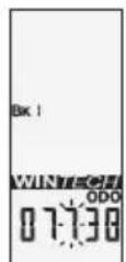
| Sensor pairing | Automatic digital by wheel rotation |
| Operating temperature | 0°C to 50°C (25°F to 122°F) |
| Water resistance | Waterproof (avoid high-pressure jet) |
| Maintenance | Clean with lukewarm soapy water, dry with a soft cloth |
| Battery life | 12 to 24 months depending on use |
| Warranty | 2 years against any defect (conditions in manual) |
| Spare parts / repairability | CR2032 batteries available, other parts through authorized dealer |
| Safety | Watch the road, wear a helmet |
| Important note | Pairing required after installation or battery replacement |
Frequently Asked Questions - Wintech EBolt MAVIC
User questions about Wintech EBolt MAVIC
0 question about this device. Answer the ones you know or ask your own.
Ask a new question about this device
Download the instructions for your Counter in PDF format for free! Find your manual Wintech EBolt - MAVIC and take your electronic device back in hand. On this page are published all the documents necessary for the use of your device. Wintech EBolt by MAVIC.
USER MANUAL Wintech EBolt MAVIC
text_image
WINTECH MAYC1.1
1. DESCRIPTIF
natural_image
Line drawing of a hand holding a tool, no text or symbols presentnatural_image
Diagram of a mechanical joint or clamp with a yellow curved arrow indicating motion (no text or symbols)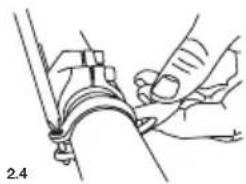
natural_image
Technical line drawing of a mechanical assembly with hands adjusting components (no text or symbols)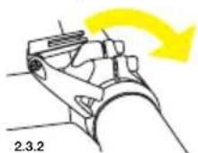
3. MISE EN PLACE ET RETRAIT DU COMPUTER SUR SON SUPPORT
natural_image
Mechanical assembly diagram showing a wheel and shaft assembly (no text or labels)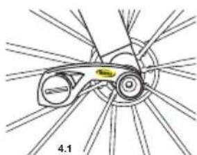
natural_image
Diagram of a bicycle wheel assembly with no visible text or symbols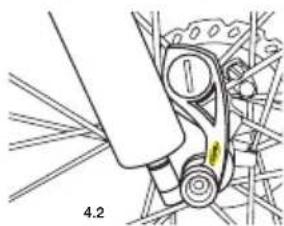
natural_image
Mechanical assembly diagram showing a lever mechanism with no visible text or symbols5. INSTALLATION DE L'AIMANT
natural_image
Mechanical assembly diagram showing linkage components (no text or labels)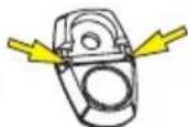
5.3
6. INSTALLATION DES BATTERIES
The image is too blurry to recognize any text content.
L

The image is too blurry to recognize any text content.
12. RÉGLAGE DES ODOMÈTRES
text_image
Diagram showing three bicycle positions with directional arrows and a distance marker, likely illustrating a physics or engineering concept.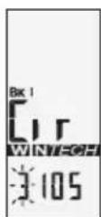
The image is too blurry to recognize any text content.
13.4
L
R
14. REMISE À ZÉRO JOURNALIÈRE
GARANTIE 2 ANS MAVIC
The Mavic team has put all its passion, experience and skill into the design and manufacture of your computer.
It will be an important aid to you in the improvement of your performance.
Thank you for putting your trust in Mavic products.
SUMMARY
- DESCRIPTION 11
- INSTALLING THE COMPUTER MOUNT 11
- FITTING/REMOVING THE COMPUTER 12
- INSTALLING THE SENSOR NUT 12
- INSTALLING THE MAGNET 12
- INSTALLING THE BATTERIES 12
- DESCRIPTION OF THE DISPLAY 13
-
FUNCTION DISPLAY SEQUENCE 13
-
DIGITAL PAIRING OF THE COMPUTER WITH THE SENSORS 13
-
PAIRING THE SECOND BIKE 14
-
SETTING THE TIME 14
-
SETTING THE ODOMETERS 15
-
SETTING THE CIRCUMFERENCE AND THE UNIT 15
-
TRIP ZERO RESET 16
-
USING THE INTERMEDIARY STOPWATCHES 16
-
CONSULTING THE INTERMEDIARY STOPWATCHES 16
-
CONSULTING THE DIFFERENT ODOMETERS 17
-
MAINTENANCE 17
After installation and before you use your computer for the first time, it is IMPERATIVE to perform the digital pairing operation described in section 9 of this guide. If you don't, there will be no communication between the computer and the different sensors and your system will not work.


text_image
WINTECH MAYC1.1
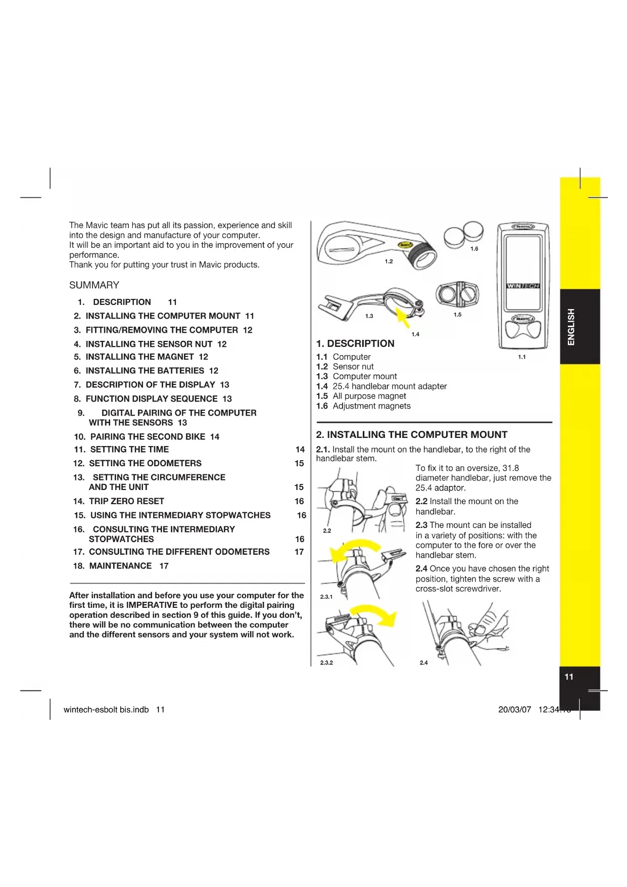
1. DESCRIPTION
1.1 Computer
1.2 Sensor nut
1.3 Computer mount
1.4 25.4 handlebar mount adapter
1.5 All purpose magnet
1.6 Adjustment magnets
2. INSTALLING THE COMPUTER MOUNT
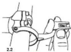
2.1. Install the mount on the handlebar, to the right of the handlebar stem.
natural_image
Line drawing of a hand holding a tool, no text or symbols presentTo fix it to an oversize, 31.8 diameter handlebar, just remove the 25.4 adaptor.
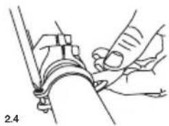
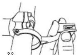
2.2 Install the mount on the handlebar.
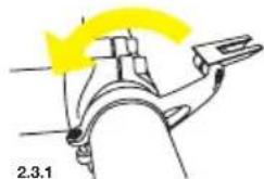
2.3 The mount can be installed in a variety of positions: with the computer to the fore or over the handlebar stem.
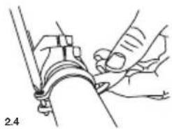
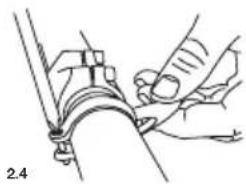
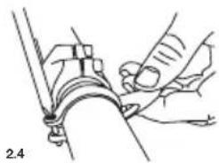
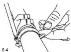
2.4 Once you have chosen the right position, tighten the screw with a cross-slot screwdriver.
natural_image
Diagram of a mechanical joint or clamp with a yellow arrow indicating direction (no text or symbols present)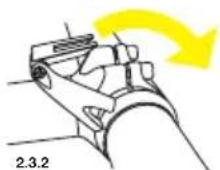
natural_image
Technical line drawing of a mechanical assembly with hands operating a tool (no text or symbols)3. FITTING/REMOVING THE COMPUTER
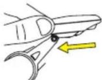
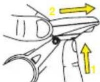
3.1 Slide the computer onto the mount from the front until it locks into place with an audible click.
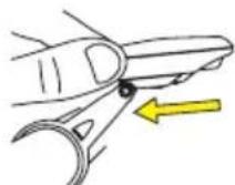
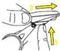
3.2 To remove the computer, press the button underneath the
mount and slide the computer out towards the front of the bike.
3.1 3.2
4. INSTALLING THE SENSOR NUT
- Installing the Sensor nut
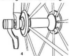
The speed sensor in this computer is integrated into a fixing
nut compatible with all quick-releases on the market.
To install it, unscrew the fixing nut on your quick-release. Insert the quick release from the left-hand side of your bike and tighten the electronic fixing nut from the right-hand side.
Adjust the tightness of the nut so that the quick-release locking lever can be sufficiently firmly pushed into the CLOSE position (if in doubt, consult your retailer or the hub manual).
4.1 Road bike.
Once sufficiently tightened, position the sensor towards the rear before closing the quick-release hub.
4.2 Mountain bike.
Once sufficiently tightened, position the sensor towards the top before closing the quick-release hub.
natural_image
Mechanical assembly diagram showing a shaft and wheel assembly with no visible text or symbols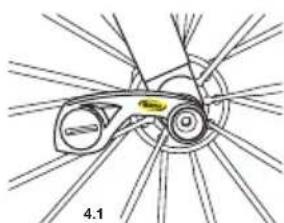
natural_image
Diagram of a bicycle wheel assembly with no visible text or symbols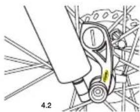
natural_image
Mechanical assembly diagram showing a lever mechanism with no visible text or symbols5. INSTALLING THE MAGNET
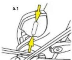
5.1 Position the magnet on a spoke so that it passes opposite either of the lever marks and at a maximum distance of 5 mm.
When used on a mountain bike, it might be necessary to use the adjustment magnets to reduce the distance between the sensor and the magnet. (5.2).
The magnet must be facing outward from the wheel.
5.3 Must be cut for use on profiled Zicral spokes
text_image
5.1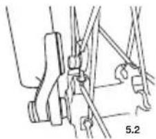
natural_image
Mechanical assembly diagram showing linkage components (no text or labels)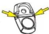
5.3
6. INSTALLING THE BATTERIES
Power supply for the computer: 1 CR2032 battery. Power supply for the speed sensor: 1 CR2032 battery. Only use this type of battery.
Installing the batteries:
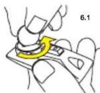
6.1 Remove the battery cover by turning it a quarter turn anticlockwise, using a coin.
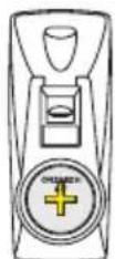
6.2 Insert the battery into its recess, keeping the + side uppermost.
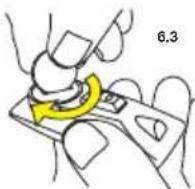
6.3 Refit the battery cover and close it by turning it a quarter turn clockwise.
Do not to use excessive force, or you will damage the unit.
Check the condition of the seal on the battery cover each time you change the battery. Replace the battery cover if the seal is damaged.
Always perform the above operations in a dry place.
6.2
Changing the computer's batteries has the effect of zeroing the following parameters: total distance, measurement unit (M or KM), wheel circumference, time.
After installation, or after changing batteries
(in sensors or computers), it is imperative to repeat the digital pairing operation described in section 9 of this notice.
Battery life: 12 to 24 months depending on use.
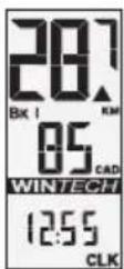
7. DESCRIPTION OF THE DISPLAY
text_image
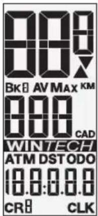
889 Bk AV MAX KM 880 CAD WINTECH ATM DST ODO 10.0:0.0.0 CR CLKBK 1, 2 or H : Number of bike used
AV : Average speed (up to 99.9) and cadence (optional – up to 180)
MAX : Maximum speed (up to 99.9) and cadence (optional – up to 180)
KM / M : Distances in kilometers or miles
X : Trend indicator
CAD : Pedaling cadence (optional – up to 180)
ATM: Stopwatch (up to 9 h 59 min 59 s)
DST : Trip distance (up to 1999.99)
ODO : Distance totalizer (up to 99.999)
- Spot speed • Spot speed
• Number of bike used • Number of bike used - Pedaling cadence (optional) • Pedaling cadence (optional)
- Trip distance • Clock
8.2 To scroll display, press left key briefly:
Screen 3: Screen 4:
- Average speed
- Max speed
• Number of bike used • Number of bike used - Average pedaling cadence (optional)
- Max pedaling cadence (optional)
- Stopwatch
- Distance totalizer (odometer)
8.1
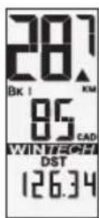
Screen 1
R
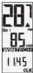
Screen 2
R
8.2
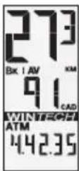
Screen 3
L
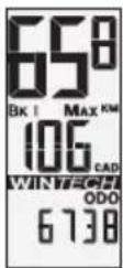
Screen 4
L
9. DIGITAL PAIRING OF THE COMPUTER WITH THE SENSORS
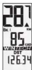
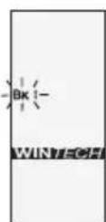
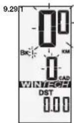
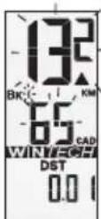
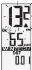
9.1 Use the right button to select screen 1 (DST). Press the right button for more than 4 seconds. The bike number (BK 1) flickers. Press the right button to validate.
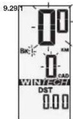
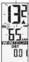
9.2 The speed (00) and pedaling cadence (0) flicker. Turn the front wheel until the speed is displayed (if you are using the pedaling cadence option, turn the cranks also). When both speed and cadence are displayed, press the right button to validate.
R 4 sec.
10. PAIRING THE SECOND BIKE
Your Wintech computer can be paired with two speed sensors simultaneously, thus enabling you to use the same computer on a second bike or with a pair of training wheels. Similarly, your Wintech computer can recognize a sensor that is specially designed for the Home-Trainer.
Once the extra sensors have been paired, your computer will know which sensor is sending messages to it and will automatically adjust to the parameters of the bike used without any intervention on your part. To use this characteristic, you must have the second bike kit, ref. 995 239 01, or the Home-Trainer kit, ref. 995 240 01, which are sold separately.

R 4 sec.
L
R
10.1 Use the right button to select screen 1 (DST).
Hold down the right button for more than 4 seconds.
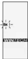
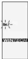
The bike number (BK 1) flickers. Use the left button to select the number of the bike chosen: BK 2 for a second bike, BK H for the home-trainer sensor (see the user guide for the Home-Trainer kit for further explanations on its use).
Briefly press the right button to validate.
R
10.2
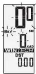
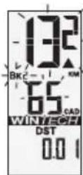
10.2 The speed (0.0) and pedaling cadence (0) flicker. Turn the front wheel until the speed is displayed (if you are using the pedaling cadence option, turn the cranks also). When both speed and cadence are displayed, press the right button to validate.
The sensor pairing is now complete.
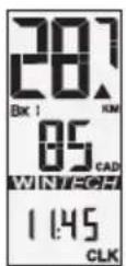
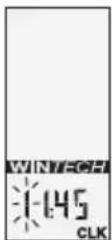
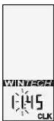
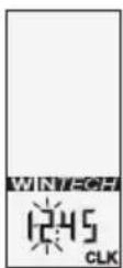
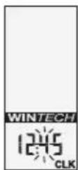
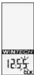
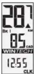
11. SETTING THE TIME
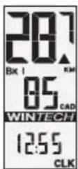
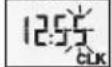
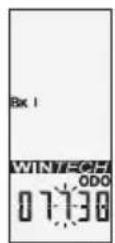
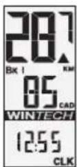
Use the right button to select screen 2 (CLK).
Hold down the right button for more than 4 seconds.
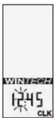
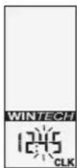
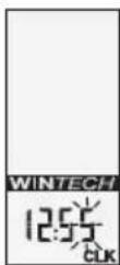
The tens of hours digit flickers.
Use the left button to set the tens of hours. Validate with the right button. The next digit flickers. Use the left button to set the hours and validate with the right button.
Set the minutes in the same way.
11
R 4 sec.
R
R
The image is too blurry to recognize any text content.
L

The image is too blurry to recognize any text content.
12. SETTING THE ODOMETERS
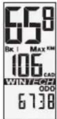
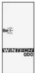
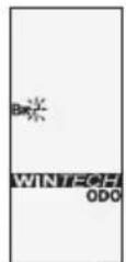
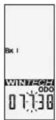
12.1 Use the left button to select screen 4 (ODO).
Hold down the right button for more than 4 seconds. The bike number flickers. If necessary, use the left button to modify the bike number
(1, 2 or H), then validate with the right button.
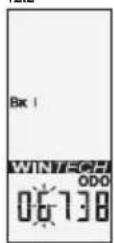
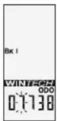
12.2 Then set the odometer for the bike selected: use the left button to modify the flickering digit, then validate and move on to the next digit with the right button. When you have set the odometer, use the right button to validate.
12.1
R 4 sec.
L
R
12.2
L

The image is too blurry to recognize any text content.
13. SETTING THE CIRCUMFERENCE AND THE UNIT
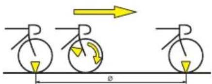
13.1 Consult the table of approximate correspondences to check your wheel circumference (see table 13.1).
For a more precise measurement, proceed as follows:
- Make a mark on the tire and on the ground at the point of contact between the tire and the ground.
- Do one full turn of the wheel and mark on the
| T | y | r | e | ∅ |
| 26"x1,5 | 2020 | 700 | Cx19 2100 | |
| 26"x1,75 | 2070 | 700 | Cx20 2110 | |
| 26"x1,9 | 2090 | 700 | Cx23 2130 | |
| 26"x2,0 | 2110 | 700 | Cx25 2140 | |
| 26"x2,1 | 2130 | 700 | Cx28 2150 | |
| 26"x2,2 | 2150 | 700 | Cx32 2170 | |
| 26"x2,3 | 2170 | |||
| 650Cx19 | 930 | |||
| 650Cx23 | 1990 | |||
text_image
Diagram showing three circular objects with arrows indicating motion or force direction, labeled with angle φ and a right-pointing arrow.ground the place where the mark on the tire touches the ground.
- Measure the distance ( ) between these two points in millimeters.
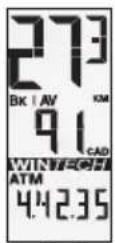
13.2 Use the left button to select screen 3 (ATM).
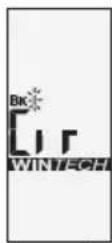
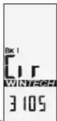
Hold down the right button for more than 4 seconds. The bike number flickers and the CIR display appears. If necessary, use the left button to modify the bike number (1, 2 or H), then validate with the right button.
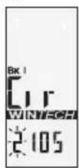
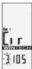
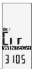
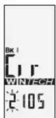
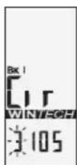
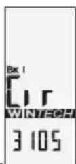
13.3 The default value 2105 appears, and the digit on the extreme left flickers. Enter the distance you have already measured (in millimeters), by modifying the flickering digit with the left button, then validate with the right.
When you have set the circumference, validate with the right button.
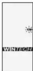
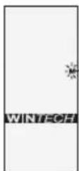
13.4 Then use the left button to select the distance unit (Miles or Kilometers). Validate with the right button.
If required, repeat the operation for bike 2.
13.2
R 4 sec.
R
13.3
L
13.4
L
R
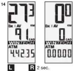
14. TRIP ZERO RESET
From any screen, press the right and left buttons simultaneously for 2 seconds to reset the following trip data to zero:
- ATM
- DST
- Average speed
- Maximum speed
- Average cadence
- Maximum cadence
- Intermediary stopwatches
text_image
14 2.73 Bk : AV KM 9.1 CAD WIN TROCH ATM 4.42.35 00 Bk : AV KM 0 CAD WIN TROCH ATM 0.00.00 L R 2 sec.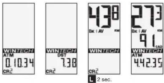
text_image
WINTECH ATM 0.10.34 CRC² WINTECH DST 7.38 CRC² 438 Bk | AV KM WINTECH CRC² 273 Bk | AV KM 91 CAD WINTECH ATM 4.42.35 L 2 sec.15. USING THE INTERMEDIARY STOPWATCHES
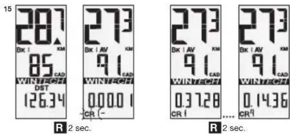
In the course of a session you can use up to 9 intermediary stopwatches in order to evaluate your performance on specific hills or sections.
Remember, the stopwatch only starts during a session i.e. when the computer already indicates a speed.
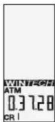
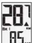
From any screen in the course of a session you can press the right button for 2 seconds to make the CR symbol flicker. The first stopwatch (CR 1) starts when you release the right button.
When you are using an intermediary stopwatch, the stopwatch time replaces the ATM data in screen 3.
To stop the first intermediary stopwatch, just press the right button.
To start the next intermediary stopwatch (CR 2), just press the right button for another 2 seconds, and so on for the 9 possible intermediary stopwatches.
text_image
15 28.7 BK I KM 85 CAD WINTEROFF DST 126.34 273 BK I AV KM 91 CAD WINTEROFF 0.00.0 CR (-) 273 BK I AV KM 91 CAD WINTEROFF 0.3728 CR I ... 273 BK I AV KM 91 CAD WINTEROFF 0.1436 CR⁷ R 2 sec. R 2 sec.16. CONSULTING THE INTERMEDIARY STOPWATCHES
Use the left button to select screen 3 (ATM).
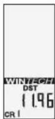
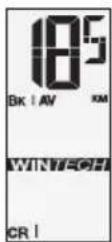
Press the left button for 2 seconds to display the data corresponding to the first intermediary stopwatch (CR 1) in loop display (2 seconds per screen): stopwatch time, distance covered and average speed.
Briefly press the left button to switch to the next stopwatch.
Press the left button for 2 seconds to quit consultation mode and return to normal display.
16
L
2 sec.
L
17. CONSULTING THE DIFFERENT ODOMETERS
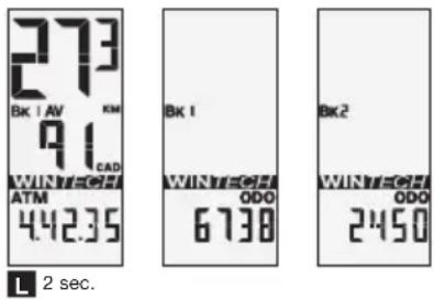
Use the left button to select screen 4 (ODO).
Press the left button for 2 seconds. The different odometers (bike 1, bike 2, home-trainer, total) are displayed in loop mode (2 seconds per screen).
The display then returns automatically to screen 4 (ODO).
17
18. MAINTENANCE
- Changing the batteries: use CR2032 batteries only (for computer and sensors).
- Changing the computer battery automatically sets the following parameters at zero: odometer, measuring unit (M or KM), wheel circumference, time. Remember to repeat the pairing operation each time you change batteries.
- Service life of batteries: 12 to 24 months depending on usage.
- Although the electronic systems are watertight, avoid subjecting them to high-pressure water jets.
-
Although they support solvents and oil-based products, avoid using this type of product in the maintenance of the different components.
-
Tip: use lukewarm water, with soap if necessary, and then wipe with a dry cloth.
- Do not leave the computer exposed to sunlight (e.g. behind a windscreen) when not in use.
- Do not disassemble any components or the guarantee will cease to be applicable.
- Cycling is a sport that can demand intense physical activity and present variable risks depending on routes and the environment. Use your road sense and keep an eye out for traffic. Remember to wear a helmet.
- Product characteristics, shape and general presentation are subject to modification without prior warning.
Instructions for Disposal of Waste Equipment by Users in Private Household

This symbol on the product or on its packaging indicates that this product must not be disposed of with your other household waste. Instead, it is your responsibility to dispose of your waste equipment by handing it over to a designated collection point for the recycling of waste electrical and electronic equipment. The separate
collection and recycling of your waste equipment at the time of disposal will help to conserve natural resources and ensure that it is recycled in a manner that protects human health and the environment. For more information about where you can drop off your waste equipment for recycling, please contact your local city office, your household waste disposal service or the shop where you purchased the product.
TECHNICAL SPECIFICATIONS
- Transmission: the use of digitally coded radio wave technology (WIN ^® ) to transmit data provides optimal reliability. However, disturbances may occur in the vicinity of electrical apparatus, overhead power lines...
- Normal operating temperature: from -10 to +50°C / 14°F to 122°F.
Avoid prolonged storage
WARNING: Changes or modifications not expressly approved by the party responsible for compliance could void the user's authority to operate the equipment.
MAVIC® 2-YEAR WARRANTY
Mavic products purchased through an authorised retailer are warranted against defects in materials and workmanship for 2 years from date of purchase by the initial user, under the conditions defined below.
In order to make a claim under this warranty, the consumer must keep proof of purchase, including the date and the name of the authorized dealer, and comply with the prescribed procedure.
OBLIGATIONS
In the event of a defect on one of its products, Mavic's sole obligation under this warranty is to repair or replace, at its discretion, the defective part or product.
Moreover, in some countries, Mavic is obliged to ensure any legal warranty defined by law, for the consumer's protection. In this respect, in France, Mavic ensures legal warranty against hidden defects under the conditions and limits of article 1641 and following of the French "Code Civil".
LIMITS OF WARRANTY
This warranty does not cover normal wear and tear or damage resulting from shipment, storage, accidents, negligence, shocks or crashes, failure to follow the user's guide and/or recommendations for use, improper assembly or assembly with incompatible products, poor maintenance, misuse, modification or alteration of the product.
The conditions of the Mavic warranty, including those applicable to product conformity, do not apply to products purchased from outlets other than retailers authorized by Mavic.
This warranty is not transferable and is only applicable to the initial purchaser.
This warranty does not cover parts that are subject to wear in normal use, such as the braking surfaces of wheel rims (if a rim braking system is used), brake pads, bearings, pawls, rear derailleur jockey wheels, batteries...
This warranty does not cover products repaired or serviced by anyone other than Mavic After-Sales Service personnel or Mavic's representative in the country concerned (1).
This warranty does not cover products whose serial numbers or identification have been erased, damaged or modified.
This warranty does not cover "Spécial Service Course Mavic®" (2) products.
This warranty does not exclude rights specific to each country.
Consumers may have other rights depending on their place of residence.
Certain jurisdictions make no provision for the exclusion or limitation of specific, incidental or consequential damages, or limitations on the warranty period; the above exclusions and limitations do not therefore apply to all. Local taxes, customs duties or freight charges may be applied. In the United States, additional rights that differ from one state to another may also be applied. Should part of this warranty be found to be inapplicable by virtue of administrative or legal proceedings, the other parts remain applicable.
CLAIMS UNDER WARRANTY - PROCEDURE
Authorised retailers are at the users' disposal to manage any warranty claims.
The authorised retailer must obtain the consent of Mavic® After-Sales Service (or its representative in the country concerned (1)) prior to returning a product under warranty. The entire product, accompanied by proof of the date of purchase (warranty card dated, signed and stamped by the authorised retailer or other proof of the date of purchase) shall be sent by the authorised retailer to Mavic® After-Sales Service (or its representative in the country concerned (1)), which will undertake the operation.
The new or repaired product shall be returned to the authorized retailer.
WARRANTY CARD
The warranty card printed on this document must be dated, signed and stamped by the authorised retailer and kept in a safe place indefinitely. It must be used for any claims.
This device complies with Part 15 of the FCC Rules. Operation is subject to the following two conditions: (1) this device may not cause harmful interference, and (2) this device must accept any interference received, including interference that may cause undesired operation.
(1) Up-to-date list available on request from: MAVIC, 74996 ANNECY CEDEX 9.
(2) Claims made by other means or without obtaining prior consent for return cannot be taken into consideration.
WIN-Tech is protected by one or more of the following patents: US 6204775 and other patent pending.
text_image
WINTECH MAYC1.1
1. LIEFERUMFANG
natural_image
Line drawing of a hand holding a tool, no text or symbols presentnatural_image
Technical line drawing of a mechanical assembly with hands adjusting components (no text or symbols)3. MONTAGE UND DEMONTIEREN DES COMPUTERS AUF DER HALTERUNG
natural_image
Mechanical assembly diagram showing a shaft and wheel assembly with no visible text or symbols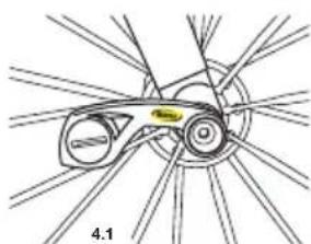
natural_image
Diagram of a bicycle wheel assembly with no visible text or symbols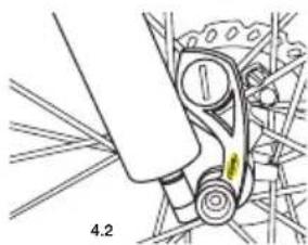
natural_image
Mechanical assembly diagram showing a lever mechanism with no visible text or symbols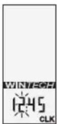
The image is too blurry to recognize any text content.

WINTECH

L

WINTECH

The image is too blurry to recognize any text content.

WINTECH
-
WINTECH

The image is too blurry to recognize any text content.
text_image
Diagram showing three bicycle positions with directional arrows and a distance marker labeled 'ø'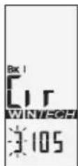
The image is too blurry to recognize any text content.
13.4
L
R
14. TAGESMESSUNGEN AUF NULL SETZEN
text_image
WINTECH MAYC1.1
1. OMSCHRIJVING
natural_image
Line drawing of a hand holding a tool, no text or symbols presentnatural_image
Diagram of a mechanical joint or clamp with a yellow arrow indicating direction (no text or symbols present)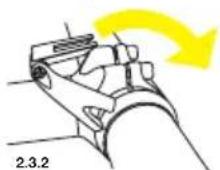
natural_image
Technical line drawing of a mechanical assembly with hands adjusting components (no text or symbols)3. HET IN- EN UITKLIKKEN VAN DE COMPUTER OP DE COMPUTERSTEUN
natural_image
Mechanical assembly diagram showing a wheel and shaft assembly (no text or labels)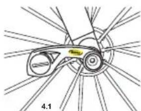
natural_image
Diagram of a bicycle wheel assembly with labeled parts (no text or symbols present)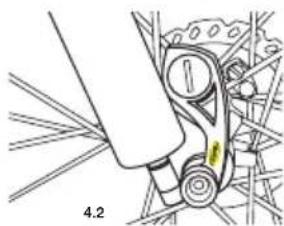
natural_image
Mechanical assembly diagram showing a lever mechanism with no visible text or symbols5. MONTAGE VAN DE MAGNEET
natural_image
Mechanical assembly diagram showing linkage components (no text or labels)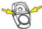
5.3
6. INSTALLATIE VAN DE BATTERIJEN
Voeding computer: 1 batterij CR2032.
text_image
287 BK I KM 85 CAD WINT/DEF DST 126.34 R 4 sec. L 10.1 Bk - WINT/DEF Bk - WINT/DEF R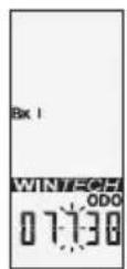
The image is too blurry to recognize any text content.
13. INSTELLING VAN DE WIELOMTREK EN DE AFSTANDSEENHEID
text_image
Diagram showing three bicycle positions with directional arrows and a distance marker labeled 'ø'text_image
WINTECH MAYC1.1
1. DESCRIPCIÓN
1.1 Ciclocomputador
1.2 Sensor roscado
1.3 Soporte del ciclocomputador
1.4 Adaptador para manillar 25.4
1.5 Imán universal
1.6 Imanes de ajuste
natural_image
Technical line drawing of a mechanical assembly with hands adjusting components (no text or symbols)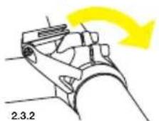
natural_image
Mechanical diagram of a bicycle wheel assembly with no visible text or symbols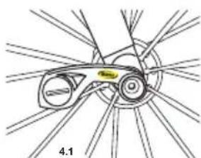
natural_image
Diagram of a bicycle wheel assembly with no visible text or symbols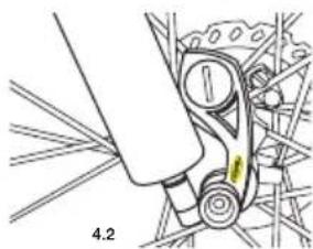
natural_image
Mechanical assembly diagram showing a lever mechanism with no visible text or symbols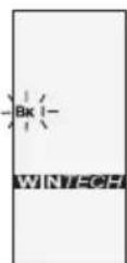
m = 311
The image is too blurry to recognize any text content.
13. AJUSTE DEL PERÍMETRO Y DE LA UNIDAD
text_image
Diagram showing three identical circular objects with arrows indicating direction, labeled with diameter 'a' and a right-pointing arrow.text_image
WINTECH MAYC1.1
1. DESCRIZIONE
natural_image
Illustration of a hand holding a tool with a labeled component (no text or symbols present)natural_image
Diagram of a mechanical joint or clamp with a yellow arrow indicating direction (no text or symbols present)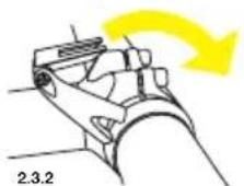

natural_image
Technical line drawing of a mechanical assembly with hands adjusting components (no text or symbols)natural_image
Mechanical assembly diagram showing a wheel and shaft assembly (no text or labels)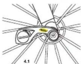
natural_image
Diagram of a bicycle wheel assembly with labeled parts (no text or symbols present)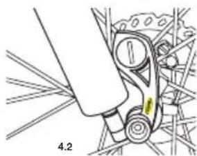
natural_image
Mechanical assembly diagram showing a lever mechanism with no visible text or symbols5. INSTALLAZIONE DEL MAGNETE
natural_image
Mechanical assembly diagram showing linkage components (no text or labels)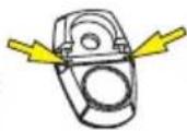
5.3
m = 311
10. APPAIAMENTO DIGITALE DELLA SECONDA BICICLETTA
text_image
287 BK I KM 85 CAD WINT=CFI DST 126.34 R 4 sec. L 10.1 Bk2- WINT=CFI R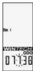
The image is too blurry to recognize any text content.
text_image
Diagram showing three identical circular objects with arrows indicating motion or force direction, labeled with diameter 'a' and a right-pointing arrow.text_image
273 BK | AV KM 91 CAD WINTEGEF ATM 4.42.35 13.2 R 4 sec. BK WINTEGEF R13.3
L
The image is too blurry to recognize any text content.
13.4
L
R
14. AZZERAMENTO GIORNALIERO
INNEHÅLLSFÖRTECKNING
- BESKRIVNING 51
- MONTERING AV DATORFÄSTET 51
- SÄTTA DIT OCH TA BORT DATORN FRÅN FÄSTET 52
- MONTERING AV DATORNS SENSORENHET 52
- MONTERA MAGNETEN 52
- BYTA BATTERIER 52
- BESKRIVNING AV INFORMATIONEN PÅ DISPLAYEN 53
- BLÄDDRING BLAND FUNKTIONER 53
- DIGITAL PARNING AV DATOR MED SENSORER 53
-
PARNING AV CYKEL NUMMER 2 54
-
INSTÄLLNING AV TID 54
- INSTÄLLNING AV ODOMETER 55
- INSTÄLLNING AV HJULOMKRETS OCH ENHET 55
- NOLLSTÄLLNING AV DAGSSTRÄCKA 56
- ANVÄNDA TIDTAGARUR FÖR DELSTRÄCKOR 56
- UTLÄSNING AV TIDER FÖR DELSTRÄCKOR 56
- VISNING AV OLIKA ODOMETER 57
- UNDERHÅLL 57
natural_image
Diagram of a mechanical joint or clamp with a yellow arrow indicating direction (no text or symbols present)
natural_image
Technical line drawing of a mechanical assembly with hands adjusting components (no text or symbols)3. SÄTTA DIT OCH TA BORT DATORN FRÅN FÄSTET
natural_image
Mechanical assembly diagram showing a shaft and wheel assembly with no visible text or symbols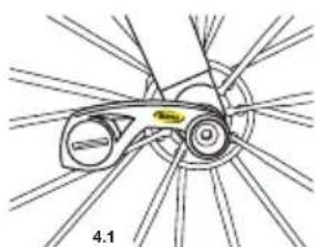
natural_image
Diagram of a bicycle wheel assembly with labeled parts (no text or symbols present)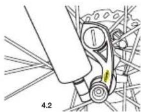
natural_image
Mechanical assembly diagram showing a lever mechanism with no visible text or symbols5. MONTERA MAGNETEN
text_image
888 Bk AV MAX KM 888 CAD WINTECH ATM DSTODO 10.0:0.0.0 CR CLKtext_image
Diagram showing three identical circular objects with arrows indicating motion or force direction, labeled with diameter 'a' and a right-pointing arrow.text_image
WINTECH MANY 1.11. MITTARIN OSAT
1.1 Mittari
1.2 Sensorimutteri
1.3 Mittarin teline
natural_image
Line drawing of a hand holding a tool, no text or symbols presentputkesta (halk. 31,8) irrota telineen asennusosa 25.4.
natural_image
Diagram of a mechanical joint or clamp with a yellow arrow indicating direction (no text or symbols present)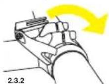
natural_image
Technical line drawing of a mechanical assembly with hands adjusting components (no text or symbols)3. MITTARIN KIINNITTÄMINEN JA IRROTUS
natural_image
Mechanical assembly diagram showing a wheel and shaft assembly (no text or labels)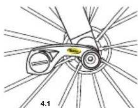
natural_image
Diagram of a bicycle wheel assembly with no visible text or symbols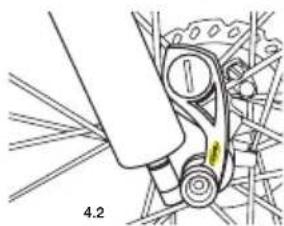
natural_image
Mechanical assembly diagram showing a lever mechanism with no visible text or symbols5. MAGNEETIN ASENNUS
natural_image
Mechanical assembly diagram showing clamping components with no visible text or symbols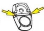
5.3
6. PARISTOJEN ASENNUS
The image is too blurry to recognize any text content.
13. PYÖRÄNKEHÄN JA MATKAN MITTAYKSIKÖN ASETUS
text_image
Diagram showing three identical circular objects with arrows indicating direction, labeled with diameter 'a' and a right-pointing arrow.text_image
WINTECH MAYC1.1
1. BESKRIVELSE
1.1 Computer
1.2 Bolt Sensor
1.3 Computer beslag
1.4 25.4 styr adapter
1.5 Magnet
1.6 Juster magneter
2. MONTERING AF COMPUTERBESLAG
natural_image
Line drawing of a hand holding a tool with a spring scale (no text or symbols)natural_image
Diagram of a mechanical clamp or bracket with a yellow curved arrow indicating motion (no text or symbols)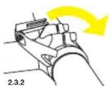
natural_image
Technical line drawing of a mechanical assembly with hands adjusting components (no text or symbols)3. MONTERING/AFMONTERING AF COMPUTER
3.1 Lad computeren glide ind på beslaget forfra, indtil det låser med en tydelig lyd.
3.2 For at afmontere computeren fra beslaget, tryk på knappen under beslaget og
skub computeren frem.
3.1 3.2
4. MONTERING AF BOLT SENSOR
natural_image
Mechanical assembly diagram showing a shaft and wheel assembly with no visible text or symbols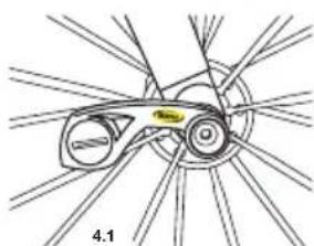
natural_image
Diagram of a bicycle wheel assembly with labeled parts (no text or symbols present)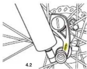
natural_image
Mechanical assembly diagram showing a lever mechanism with no visible text or symbols5. MONTERING AF MAGNET
text_image
888 BKB AV MAX KM 888 CAD WINTECH ATM DSTODO 10.0:0.0.0 CRB CLK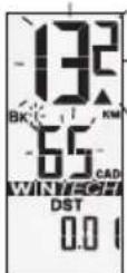
The image is too blurry to recognize any text content.
10. SYNKRONISERING TIL NUMMER 2 CYKEL

The image is too blurry to recognize any text content.
12. INDSTIL DISTANCETÆLLERE
text_image
Diagram showing three circular objects with arrows indicating motion or force direction, labeled with angle θ and dimension 'a'text_image
WINTECH MAYC1.1
1. OPIS
natural_image
Illustration of a hand holding a tool with a curved cable, no text or symbols presentnatural_image
Diagram of a mechanical joint or clamp with a yellow arrow indicating direction (no text or symbols present)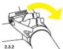

natural_image
Technical line drawing of a mechanical assembly with hands adjusting components (no text or symbols)3. ZAKŁADANIE I ZDEJMOWANIE LICZNIKA ZE WSPORNIKA
natural_image
Mechanical diagram of a wheel assembly with shafts and levers (no text or labels)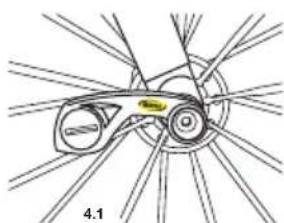
natural_image
Diagram of a bicycle wheel assembly with labeled parts (no text or symbols present)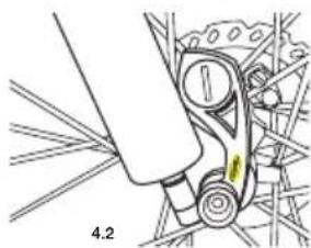
natural_image
Mechanical assembly diagram showing a lever mechanism with no visible text or symbols5. INSTALACJA MAGNESU
text_image
Diagram showing three bicycle positions with directional arrows and a distance marker labeled 'ø'text_image
WINTECH MAYC1.1
1. OBSAH BALENÍ
natural_image
Illustration of a hand holding a tool with a clamp, labeled '2.2' (no text or symbols on the diagram itself)natural_image
Technical line drawing of a mechanical assembly with hands adjusting components (no text or symbols)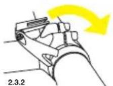
3. NASAZOVÁNÍ A SUNDÁVÁNÍ COMPUTERU Z DRŽÁKU
natural_image
Mechanical diagram of a bicycle wheel assembly with no visible text or symbols
natural_image
Diagram of a bicycle wheel assembly with labeled parts (no text or symbols present)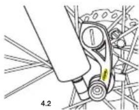
natural_image
Mechanical assembly diagram showing a lever mechanism with no visible text or symbols5. MONTÁŽ MAGNETU
natural_image
Mechanical assembly diagram showing linkage components (no text or labels)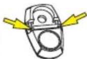
5.3
6. MONTÁŽ BATERIE
Computer : 1 Baterie CR2032
Senzor v rychloupínači : 1 Baterie CR2032
m = 311
13. NASTAVENÍ OBVODU KOLA A DÉLKOVÉ MÍRY KM/M
text_image
Diagram showing three bicycle wheels with directional arrows and a distance measurement labeled 'a'text_image
WINTECH WINTECH 1.11. パッケージの内容
natural_image
Technical line drawing of a mechanical assembly with hands adjusting components (no text or symbols)94
95
95
96
94
95
95
96
94
95
95
96
94
95
95
96
94
95
95
96
94
95
95
96
94
95
95
96
94
95
95
96
94
95
95
96
94
95
95
96
94
95
95
96
94
95
96
94
95
95
96
94
95
95
96
94
95
95
96
94
95
95
96
9 94 95 95 96
9 94 95 95 96
9 94 95 95 96
9 94 95 95 96
9 94 95 95 96
9 94 95 95 96
9 94 95 95 96
9 94 95 95 96
9 94 95 95 96
natural_image
Mechanical assembly diagram showing a wheel and shaft assembly (no text or labels)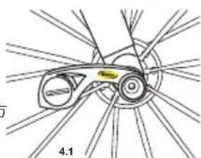
natural_image
Diagram of a bicycle wheel with visible hub and spokes, labeled '4.1' (no text or symbols on the diagram itself)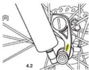
text_image
向 4.25. マグネットの取り付け
text_image
20.7 BK I KM 85 CAD WINT-061 DST 126.34 R 4 sec. L 10.1 WINT-061 Bk2- WINT-061 R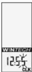
The image is too blurry to recognize any text content.