WINTECH ULTIMATE - Bike computer MAVIC - Free user manual and instructions
Find the device manual for free WINTECH ULTIMATE MAVIC in PDF.
User questions about WINTECH ULTIMATE MAVIC
0 question about this device. Answer the ones you know or ask your own.
Ask a new question about this device
Download the instructions for your Bike computer in PDF format for free! Find your manual WINTECH ULTIMATE - MAVIC and take your electronic device back in hand. On this page are published all the documents necessary for the use of your device. WINTECH ULTIMATE by MAVIC.
USER MANUAL WINTECH ULTIMATE MAVIC
GARANTIE 2 ANS MAVIC
The Mavic team has put all its passion, experience and skill into the design and manufacture of your computer. It will be an important aid to you in the improvement of your performance.
Thank you for putting your trust in Mavic products.
SUMMARY
1.DESCRIPTION 11
2. INSTALLING THE COMPUTER MOUNT 11
3. FITTING/REMOVING THE COMPUTER 12
4. INSTALLING THE MAGNET BRACKET 12
5. INSTALLING THE SPEED SENSOR 12
6. INSTALLING THE BATTERIES 12
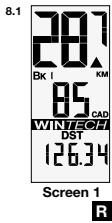
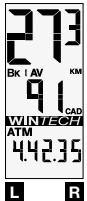
7.DESCRIPTION OF THE DISPLAY 13
8. FUNCTION DISPLAY SEQUENCE 13
9. DIGITAL PAIRING OF THE COMPUTER WITH THE SENSORS 13
10. PAIRING THE SECOND BIKE 14
11. SETTING THE TIME 14
12. SETTING THE ODOMETERS 15
13. SETTING THE CIRCUMFERENCE AND THE UNIT 15
14.TRIP ZERO RESET 16
15. USING THE INTERMEDIARY STOPWATCHES 16
16. CONSULTING THE INTERMEDIARY STOPWATCHES 16
17. CONSULTING THE DIFFERENT ODOMETERS 17
18. MAINTENANCE 17
After installation and before you use your computer for the first time, it is IMPERATIVE to perform the digital pairing operation described in section 9 of this guide. If you don't, there will be no communication between the computer and the different sensors and your system will not work.
1.1

1.5

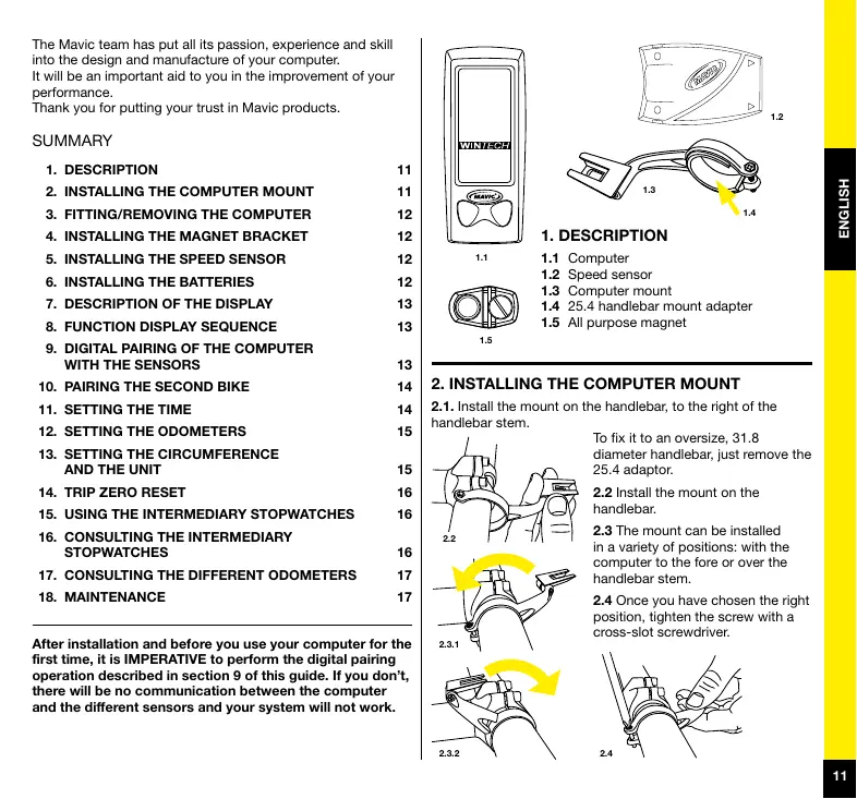
1.DESCRIPTION
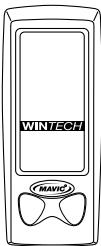
1.1 Computer
1.2 Speed sensor
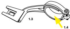
1.3 Computer mount
1.4 25.4 handlebar mount adapter
1.5 All purpose magnet
2. INSTALLING THE COMPUTER MOUNT
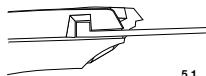
2.1. Install the mount on the handlebar, to the right of the handlebar stem.
To fix it to an oversize, 31.8 diameter handlebar, just remove the 25.4 adaptor.
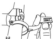
2.2 Install the mount on the handlebar.
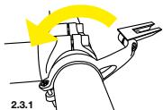
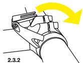
2.3 The mount can be installed in a variety of positions: with the computer to the fore or over the handlebar stem.
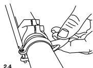
2.4 Once you have chosen the right position, tighten the screw with a cross-slot screwdriver.
3. FITTING/REMOVING THE COMPUTER
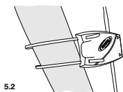
3.1 Slide the computer onto the mount from the front until it locks into place with an audible click.
3.2 To remove the computer, press the button underneath the mount and slide
the computer out towards the front of the bike.
3.1
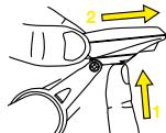
3.2
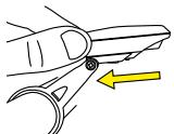
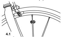
4. INSTALLING THE MAGNET BRACKET
Place the magnet bracket on a spoke on the right side of the wheel, about 3 cm from the rim. The magnet must be turned toward the outside of the wheel.
Caution: If you are using a wheel with extra flat spokes, you need to cut the tabs on the magnet bracket beforehand.
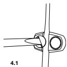
4.1
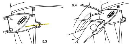
5. INSTALLING THE SPEED SENSOR
5.1 Insert a wire tie into each slot designed for this purpose from the sensor side. The head of the wire tie must go in its slot as far as possible.
5.2 Place the sensor on the right blade of the fork (the sensor must be pointing forward); close the fixing collars without tightening them.
5.3 Adjust the position of the speed sensor so the center of the magnet is aligned with one of the arrows on the sensor. The distance between the magnet and the sensor must be between 5 - 10 mm.
5.4 Tighten the wire tires and cut them flush.
IMPORTANT: At this point, your computer is not yet ready to function. You still need to set the necessary programs, and then perform the pairing operation of your device.
6. INSTALLING THE BATTERIES
Power supply for the computer: 1 CR2032 battery.
Power supply for the speed sensor: 1 CR2032 battery.
Only use this type of battery.
Installing the batteries:
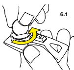
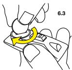
6.1 Remove the battery cover by turning it a quarter turn anticlockwise, using a coin.
6.2 Insert the battery into its recess, keeping the + side uppermost.
6.3 Refit the battery cover and close it by turning it a quarter turn clockwise.
Do not to use excessive force, or you will damage the unit.
Check the condition of the seal on the battery cover each time you change the battery. Replace the battery cover if the seal is damaged.
Always perform the above operations in a dry place.

6.2
Changing the computer's batteries has the effect of zeroing the following parameters: total distance, measurement unit (M or KM), wheel circumference, time.
After installation, or after changing batteries (in sensors or computers), it is imperative to repeat the digital pairing operation described in section
Battery life: 12 to 24 months depending on use.
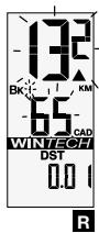
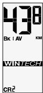
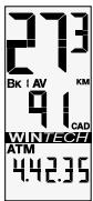
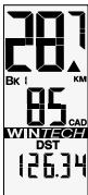
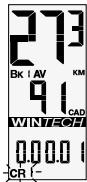
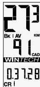
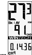
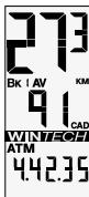
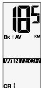
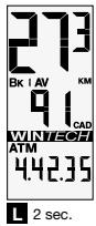
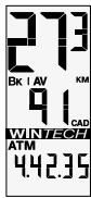
7.DESCRIPTION OF THE DISPLAY

BK 1, 2 or H: Number of bike used
AV: Average speed (up to 99.9) and cadence (optional - up to 180)
MAX: Maximum speed (up to 99.9) and cadence (optional - up to 180
KM/M: Distances in kilometers or miles
Trend indicator
CAD: Pedaling cadence (optional - up to 180)
ATM: Stopwatch (up to 9 h 59 min 59 s)
DST: Trip distance (up to 1999.99)
ODO: Distance totalizer (up to 99.999)
- Spot speed
Number of bike used - Pedaling cadence (optional)
- Trip distance
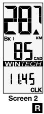
Screen 2:
- Spot speed
Number of bike used - Pedaling cadence (optional)
Clock
8.2 To scroll display, press left key briefly:
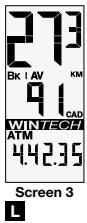
Screen 3:
Average speed
Number of bike used
Average pedaling cadence (optional)
- Stopwatch
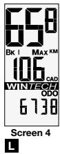
Screen 4:
Max speed
Number of bike used
- Max pedaling cadence (optional)
- Distance totalizer (odometer)
8.2
9. DIGITAL PAIRING OF THE COMPUTER WITH THE SENSORS
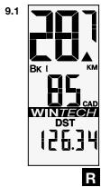
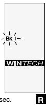
9.1 Use the right button to select screen 1 (DST). Press the right button for more than 4 seconds. The bike number (BK 1) flickers. Press the right button to validate.
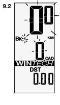
9.2 The speed (00) and pedaling cadence (0) flicker. Turn the front wheel until the speed is displayed (if you are using the pedaling cadence option, turn the cranks also). When both speed and cadence are displayed, press the right button to validate.
10. PAIRING THE SECOND BIKE
Your Wintech computer can be paired with two speed sensors simultaneously, thus enabling you to use the same computer on a second bike or with a pair of training wheels. Similarly, your Wintech computer can recognize a sensor that is specially designed for the Home-Trainer.
Once the extra sensors have been paired, your computer will know which sensor is sending messages to it and will automatically adjust to the parameters of the bike used without any intervention on your part. To use this characteristic, you must have the second bike kit, ref. 995 239 01, or the Home-Trainer kit, ref. 995 240 01, which are sold separately.
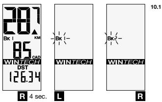
10.1 Use the right button to select screen 1 (DST).
Hold down the right button for more than 4 seconds.
The bike number (BK 1) flickers. Use the left button to select the number of the bike chosen: BK 2 for a second bike, BK H for the home-trainer sensor (see the user guide for the HomeTrainer kit for further explanations on its use).
Briefly press the right button to validate.
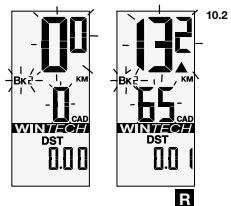
10.2 The speed (0.0) and pedaling cadence (0) flicker. Turn the front wheel until the speed is displayed (if you are using the pedaling cadence option, turn the cranks also). When both speed and cadence are displayed, press the right button to validate.
The sensor pairing is now complete.
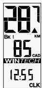
11. SETTING THE TIME
Use the right button to select screen 2 (CLK).
Hold down the right button for more than 4 seconds.
The tens of hours digit flickers.
Use the left button to set the tens of hours. Validate with the right button. The next digit flickers. Use the left button to set the hours and validate with the right button.
Set the minutes in the same way.


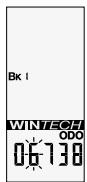
12. SETTING THE ODOMETERS
12.1 Use the left button to select screen 4 (ODO).
Hold down the right button for more than 4 seconds. The bike number flickers. If necessary, use the left button to modify the
bike number
(1,2 or H), then validate with the right button.
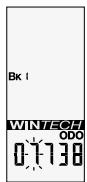
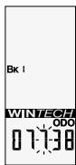
12.2 Then set the odometer for the bike selected: use the left button to modify the flickering digit, then validate and move on to the next digit with the right button. When you have set the odometer, use the right button to validate.

12.1
R 4 sec.

L

R
12.2
L
R
R
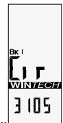
13. SETTING THE CIRCUMFERENCE AND THE UNIT
13.1 Consult the table of approximate correspondences to check your wheel circumference (see table 13.1).
For a more precise measurement, proceed as follows:
- Make a mark on the tire and on the ground at the point of contact between the tire and the ground.
- Do one full turn of the wheel and mark on the
13.1
| Tyre | Ø | Tyre | Ø |
| 26"x1,5 | 2020 | 650Cx23 | 1990 |
| 26"x1,75 | 2070 | 700Cx19 | 2100 |
| 26"x1,9 | 2090 | 700Cx20 | 2110 |
| 26"x2,0 | 2110 | 700Cx23 | 2130 |
| 26"x2,1 | 2130 | 700Cx25 | 2140 |
| 26"x2,2 | 2150 | 700Cx28 | 2150 |
| 26"x2,3 | 2170 | 700Cx32 | 2170 |
| 650Cx19 | 1930 | 700CX35 | 2200 |
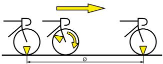
ground the place where the mark on the tire touches the ground.
- Measure the distance () between these two points in millimeters.
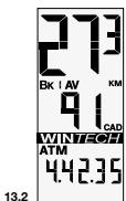
13.2 Use the left button to select screen 3 (ATM).
Hold down the right button for more than 4 seconds. The bike number flickers and the CIR display appears. If necessary, use the left button to modify the bike number (1, 2 or H), then validate with the right button.
13.3 The default value 2105 appears, and the digit on the extreme left flickers. Enter the distance you have already measured (in millimeters), by modifying the flickering digit with the left button, then validate with the right.
When you have set the circumference, validate with the right button.
13.4 Then use the left button to select the distance unit (Miles or Kilometers). Validate with the right button.
If required, repeat the operation for bike 2.

R 4 sec.

13.3


13.4


R

14. TRIP ZERO RESET
From any screen, press the right and left buttons simultaneously for 2 seconds to reset the following trip data to zero:
-ATM
-DST
- Average speed
- Maximum speed
- Average cadence
- Maximum cadence
- Intermediary stopwatches
14
2 sec.

2 sec.
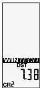
To stop the first intermediary stopwatch, just press the right button.
To start the next intermediary stopwatch (CR 2), just press the right button for another 2 seconds, and so on for the 9 possible intermediary stopwatches.
15
R 2 sec.
R 2 sec.
16. CONSULTING THE INTERMEDIARY STOPWATCHES
Use the left button to select screen 3 (ATM).
Press the left button for 2 seconds to display the data corresponding to the first intermediary stopwatch (CR 1) in loop display (2 seconds per screen): stopwatch time, distance covered and average speed.
Briefly press the left button to switch to the next stopwatch.
Press the left button for 2 seconds to quit consultation mode and return to normal display.
15. USING THE INTERMEDIARY STOPWATCHES
In the course of a session you can use up to 9 intermediary stopwatches in order to evaluate your performance on specific hills or sections.
Remember, the stopwatch only starts during a session i.e. when the computer already indicates a speed.
From any screen in the course of a session you can press the right button for 2 seconds to make the CR symbol flicker. The first stopwatch (CR 1) starts when you release the right button.
When you are using an intermediary stopwatch, the stopwatch time replaces the ATM data in screen 3.
16


2 sec.
L
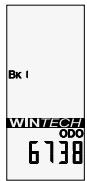
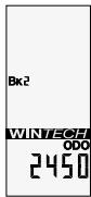
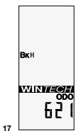
17. CONSULTING THE DIFFERENT ODOMETERS
Use the left button to select screen 4 (ODO).
Press the left button for 2 seconds. The different odometers (bike 1, bike 2, home-trainer, total) are displayed in loop mode (2 seconds per screen).
The display then returns automatically to screen 4 (ODO).

18. MAINTENANCE
- Changing the batteries: use CR2032 batteries only (for computer and sensors).
- Changing the computer battery automatically sets the following parameters at zero: odometer, measuring unit (M or KM), wheel circumference, time. Remember to repeat the pairing operation each time you change batteries.
Service life of batteries: 12 to 24 months depending on usage.
Although the electronic systems are watertight, avoid subjecting them to high-pressure water jets. - Although they support solvents and oil-based products, avoid using this type of product in the maintenance of the different components.
Tip: use lukewarm water, with soap if necessary, and then wipe with a dry cloth.
- Do not leave the computer exposed to sunlight (e.g. behind a windscreen) when not in use.
- Do not disassemble any components or the guarantee will cease to be applicable.
- Cycling is a sport that can demand intense physical activity and present variable risks depending on routes and the environment. Use your road sense and keep an eye out for traffic. Remember to wear a helmet.
- Product characteristics, shape and general presentation are subject to modification without prior warning.
Instructions for Disposal of Waste Equipment by Users in Private Household

This symbol on the product or on its packaging indicates that this product must not be disposed of with your other household waste. Instead, it is your responsibility to dispose of your waste equipment by handing it over to a designated collection point for the recycling of waste electrical and electronic equipment. The separate
collection and recycling of your waste equipment at the time of disposal will help to conserve natural resources and ensure that it is recycled in a manner that protects human health and the environment. For more information about where you can drop off your waste equipment for recycling, please contact your local city office, your household waste disposal service or the shop where you purchased the product.
TECHNICAL SPECIFICATIONS
- Transmission: the use of digitally coded radio wave technology (WIN®) to transmit data provides optimal reliability. However, disturbances may occur in the vicinity of electrical apparatus, overhead power lines...
- Normal operating temperature: from -10 to +50^ / 14^ to 122^ .
Avoid prolonged storage
WARNING: Changes or modifications not expressly approved by the party responsible for compliance could void the user's authority to operate the equipment.
MAVIC® 2-YEAR WARRANTY
Mavic products purchased through an authorised retailer are warranted against defects in materials and workmanship for 2 years from date of purchase by the initial user, under the conditions defined below.
In order to make a claim under this warranty, the consumer must keep proof of purchase, including the date and the name of the authorized dealer, and comply with the prescribed procedure.
OBLIGATIONS
In the event of a defect on one of its products, Mavic's sole obligation under this warranty is to repair or replace, at its discretion, the defective part or product.
Moreover, in some countries, Mavic is obliged to ensure any legal warranty defined by law, for the consumer's protection. In this respect, in France, Mavic ensures legal warranty against hidden defects under the conditions and limits of article 1641 and following of the French "Code Civil".
LIMITS OF WARRANTY
This warranty does not cover normal wear and tear or damage resulting from shipment, storage, accidents, negligence, shocks or crashes, failure to follow the user's guide and/or recommendations for use, improper assembly or assembly with incompatible products, poor maintenance, misuse, modification or alteration of the product.
The conditions of the Mavic warranty, including those applica-ble to product conformity, do not apply to products purchased from outlets other than retailers authorized by Mavic.
This warranty is not transferable and is only applicable to the initial purchaser.
This warranty does not cover parts that are subject to wear in normal use, such as the braking surfaces of wheel rims (if a rim braking system is used), brake pads, bearings, pawls, rear derailleur jockey wheels, batteries...
This warranty does not cover products repaired or serviced by anyone other than Mavic After-Sales Service personnel or Mavic's representative in the country concerned (1).
This warranty does not cover products whose serial numbers or identification have been erased, damaged or modified.
This warranty does not cover "Spécial Service Course Mavic" (2) products.
This warranty does not exclude rights specific to each country. Consumers may have other rights depending on their place of residence.
Certain jurisdictions make no provision for the exclusion or limitation of specific, incidental or consequential damages, or limitations on the warranty period; the above exclusions and limitations do not therefore apply to all. Local taxes, customs duties or freight charges may be applied. In the United States, additional rights that differ from one state to another may also be applied. Should part of this warranty be found to be inapplicable by virtue of administrative or legal proceedings, the other parts remain applicable.
CLAIMS UNDER WARRANTY - PROCEDURE
Authorised retailers are at the users' disposal to manage any warranty claims.
The authorised retailer must obtain the consent of Mavic® After-Sales Service (or its representative in the country concerned (1)) prior to returning a product under warranty. The entire product, accompanied by proof of the date of purchase (warranty card dated, signed and stamped by the authorised retailer or other proof of the date of purchase) shall be sent by the authorised retailer to Mavic® After-Sales Service (or its representative in the country concerned (1)), which will undertake the operation.
The new or repaired product shall be returned to the authorized retailer.
This device complies with Part 15 of the FCC Rules. Operation is subject to the following two conditions: (1) this device may not cause harmful interference, and (2) this device must accept any interference received, including interference that may cause undesired operation.
(1) Up-to-date list available on request from: MAVIC, 74996 ANNECY CEDEX 9.
(2) Claims made by other means or without obtaining prior consent for return cannot be taken into consideration.
WIN-Tech is protected by one or more of the following patents: US 6204775 and other patent pending.

m = 311
13.3


13.4

L

14. AZZERAMENTO GIORNALIERO
9. DIGITAL PARNING AV DATOR MED SENSOR
Gwarancja ne obejmuje konsekwencj normalné zužyciaXXXXXXXX XXXXXXX XXXXXXX XXXXXXX XXXXXXX XXXXXXX XXXXXXX XXXXXXX XXXXXXX XXXXXXX XXXXXXX XXXXXXX XXXXXXX XXXXXXX XXXXXXX XXXXXXX XXXXXXX XXXXXXX XXXXXXX XXXXXXX XXXXXXX XXXXXXX XXXXXXX XXXXXXX XXXXXXX XXXXXXX XXXXXXX XXXXXXX XXXXXXX XXXXXXX XXXXXXX XXXXXXX XXXXXXX XXXXXXX XXXXXXX XXXXXXX XXXXXXX XXXXXXX XXXXXXX XXXXXXX XXXXXXX XXXXXXX XXXXXXX XXXXXXX XXXXXXX XXXXXXX XXXXXXX XXXXXXX XXXXXXX XXXXXXX XXXXXXX XXXXXXXXXXX XXXXXXXXXXX XXXXXXXXXXX XXXXXXXXXXX XXXXXXXXXXX XXXXXXXXXXX XXXXXXXXXXX XXXXXXXXXXX XXXXXXXXXXX XXXXXXXXXXX XXXXXXXXXXX XXXXXXXXXXX XXXXXXXXXXX XXXXXXXXXXX XXXXXXXXXXX XXXXXXXXXXX XXXXXXXXXXX XXXXXXXXXXX XXXXXXXXXXX XXXXXXXXXXX XXXXXXXXXXX XXXXXXXXXXX XXXXXXXXXXX XXXXXXXXXXX XXXXXXXXXXX XXXXXXXXXXX XXXXXXXXXXX XXXXXXXXXXX XXXXXXXXXXX XXXXXXXXXXX XXXXXXXXXXX XXXXXXXXXXX XXXXXXXXXXX XXXXXXXXXXX XXXXXXXXXXX XXXXXXXXXXX XXXXXXXXXXX XXXXXXXXXXX XXXXXXXXXXX XXXXXXXXXXX XXXXXXXXXXX XXXXXXXXXXX XXXXXXXXXXX XXXXXXXXXXX XXXXXXXXXXX XXXXXXXXXXX XXXXXXXXXXX XXXXXXXXXXX XXXXXXXXXXX XXXXXXXXXXX XXXxxxxxxxx
POSTUP PřI UPLATNěNI REKLAMACE
This is a special Service Course Mavic (2)製品。
適用さ毎せん。
Declaration of conformity
Nous, MAVIC
We,
74996 Annecy Cedex 9 (France)
declare under our sole responsibility that the products :
WinTech FS ref. 996 812 01
WinTech Ultimate ref. 996 646 01
name,type or model, batch or serial number, possibly sources and number of items)
to which this declaration relates
satisfontauxdispositionsde la(des)directivesduConseil
satisfy the provisions of Directive(s)
n^ 89/336/CEE du 3 Mai 1989
n^ 99/5/CEE 9 Mars 1999
Name and signature or equivalent marking of authorized person

Responsible developments electroniques
Name and signature or equivalent marking of authorized person

J.JOURDE AUTIER Responsible R&D