
GTA 470 DSP - Car stereo BLAUPUNKT - Free user manual and instructions
Find the device manual for free GTA 470 DSP BLAUPUNKT in PDF.
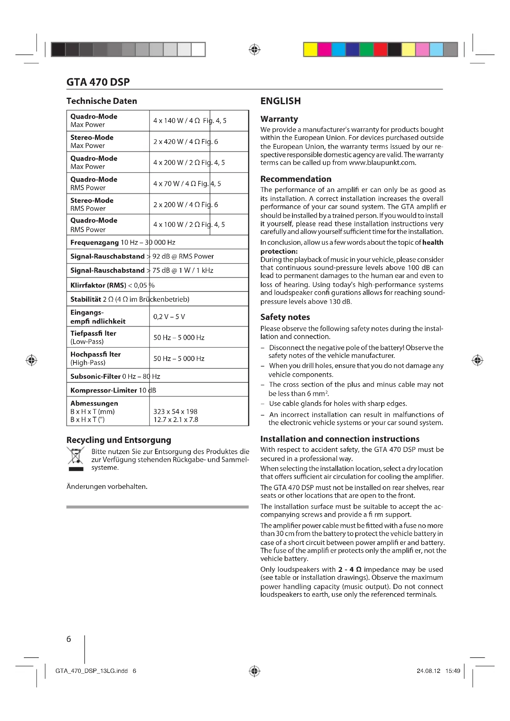
| Product Type | 4-channel amplifier with digital processor (DSP) |
| Brand | Blaupunkt |
| Model | GTA 470 DSP |
| Max power (4-channel) | 4 x 140 W / 4 Ω, 4 x 200 W / 2 Ω |
| RMS power (4-channel) | 4 x 70 W / 4 Ω, 4 x 100 W / 2 Ω |
| Max power (bridged stereo) | 2 x 420 W / 4 Ω |
| RMS power (bridged stereo) | 2 x 200 W / 4 Ω |
| Frequency response | 10 Hz – 30 000 Hz |
| Signal-to-noise ratio | > 92 dB (at RMS power), > 75 dB (at 1 W/1 kHz) |
| Distortion rate (RMS) | < 0.05% |
| Stability | 2 Ω (4 Ω in bridged mode) |
| Input sensitivity | 0.2 V – 5 V |
| Low-pass / high-pass filter | 50 Hz – 5,000 Hz |
| Subsonic filter | 0 Hz – 80 Hz |
| Limiter / compressor | 10 dB |
| Built-in fuses | 2 x 20 A |
| Power supply | 12 V DC (vehicle battery) |
| Dimensions (L x H x D) | 323 x 54 x 198 mm |
| Maintenance and cleaning | Clean with a dry cloth. Avoid abrasive products. |
| Safety | Disconnect the battery before installation. Use cables with a cross-section of ≥ 6 mm². Main fuse near the battery. |
Frequently Asked Questions - GTA 470 DSP BLAUPUNKT
User questions about GTA 470 DSP BLAUPUNKT
0 question about this device. Answer the ones you know or ask your own.
Ask a new question about this device
Download the instructions for your Car stereo in PDF format for free! Find your manual GTA 470 DSP - BLAUPUNKT and take your electronic device back in hand. On this page are published all the documents necessary for the use of your device. GTA 470 DSP by BLAUPUNKT.
USER MANUAL GTA 470 DSP BLAUPUNKT
natural_image
Exterior view of a black electronic device labeled 'BLAUPURET' with ports and connectors (no readable text beyond branding)www.blaupunkt.com

BLAUPUNKT
GTA 470 DSP
DEUTSCH 3
Installation / connection ....46
FRANÇAIS 9
Montage / Raccordement ....46
ESPAÑOL 13
FRONT dB/Oct, REAR dB/Oct und SUB dB/Oct Schalter
We provide a manufacturer's warranty for products bought within the European Union. For devices purchased outside the European Union, the warranty terms issued by our respective responsible domestic agency are valid. The warranty terms can be called up from www.blaupunkt.com.
Recommendation
The performance of an amplifier can only be as good as its installation. A correct installation increases the overall performance of your car sound system. The GTA amplifier should be installed by a trained person. If you would to install it yourself, please read these installation instructions very carefully and allow yourself sufficient time for the installation.
In conclusion, allow us a few words about the topic of health protection:
During the playback of music in your vehicle, please consider that continuous sound-pressure levels above 100 dB can lead to permanent damages to the human ear and even to loss of hearing. Using today's high-performance systems and loudspeaker configurations allows for reaching sound-pressure levels above 130 dB.
Safety notes
Please observe the following safety notes during the installation and connection.
- Disconnect the negative pole of the battery! Observe the safety notes of the vehicle manufacturer.
- When you drill holes, ensure that you do not damage any vehicle components.
- The cross section of the plus and minus cable may not be less than 6mm^2 .
- Use cable glands for holes with sharp edges.
- An incorrect installation can result in malfunctions of the electronic vehicle systems or your car sound system.
Installation and connection instructions
With respect to accident safety, the GTA 470 DSP must be secured in a professional way.
When selecting the installation location, select a dry location that offers sufficient air circulation for cooling the amplifier. The GTA 470 DSP must not be installed on rear shelves, rear seats or other locations that are open to the front.
The installation surface must be suitable to accept the accompanying screws and provide a firm support.
The amplifier power cable must be fitted with a fuse no more than 30 cm from the battery to protect the vehicle battery in case of a short circuit between power amplifier and battery. The fuse of the amplifier protects only the amplifier, not the vehicle battery.
Only loudspeakers with 2 - 4 Ω impedance may be used (see table or installation drawings). Observe the maximum power handling capacity (music output). Do not connect loudspeakers to earth, use only the referenced terminals.
GTA 470 DSP
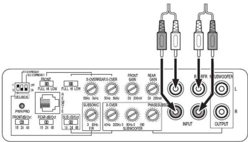
Audio inputs
The preamplifi er outputs are connected to the cinch (RCA) sockets via a shielded audio line (see Fig. 3).
Plus / minus connection
- We recommend a minimum cross section of 6mm^2 .
- Route commercially available plus cables to the battery and connect via fuse holder.
- Use cable glands for holes with sharp edges.
- Securely fasten commercially available minus cables to a noise-free earth point (chassis screw, chassis metal) (not to the minus pole of the battery).
- Scrap the contact surfaces of the earth point until they are bright and grease with graphite grease.
Integrated fuses (2 x 20 A)
The fuses integrated in the amplifier protect the power amplifier and the entire electrical system in case of an error. If a replacement fuse is used, never bridge fuses or replace them with a type with higher current.
Connection examples
Connection of the voltage supply ......Fig. 2
Audio inputs ......Fig. 3
Loudspeaker connections ......Fig. 4 - 8
Remote control connection (optional equipment) .....Fig. 9
+12V
Remote connection of the amplifier with switchable +12 V voltage source.
This allows the amplifier to be switched on and off using the on/off-switch of the car sound system.
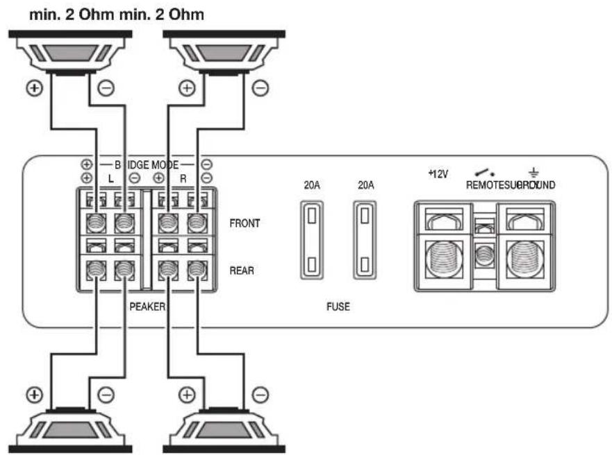
Loudspeaker connections
(If the amplifier is to be jumpered, continue with the section "Bridged loudspeaker connections" at this point).
As with every audio component, the correct polarisation of amplifier and loudspeakers is of essentially importance for a good bass response. For this reason, ensure that the positive connection (+) of the amplifier is connected with the positive connection (+) of the loudspeaker; the same applies to the negative connections (-). In addition, the left amplifier channel must be connected with the left loudspeaker and the right amplifier channel with the right loudspeaker.
Bridged loudspeaker connections
The GTA amplifi er can also be bridged for a mono configura-tion. This allows the amplifi er to be used for one or several subwoofers or a mid-range driver. In this confi guration, the amplifi er combines the right and left channel to a single-channel output (mono output).
Note:
The amplifier can add the right and left signal information only if the right as well as the left cinch (RCA) connection were carried out.
Caution:
In a bridge circuit, the amplifi er load must be 4 Ω or higher. A lower load leads to an overheating or switch-off of the amplifi er and can cause permanent damages.
Subwoofer connection
The GTA 470 DSP features three different options of connecting a subwoofer:
- An active subwoofer or an additional amplifier are connected with a cinch (RCA) cable to the two SUBWOOFER OUTPUT sockets (see Fig. 7). The setting options of the integrated DSP (Digital Sound Processor) can be used in this case.
- A passive subwoofer is connected to the bridged loudspeaker output (see the section "Bridged loudspeaker connections"). To be able to use the setting options of the integrated DSP (Digital Sound Processor), the two REAR INPUT sockets must additionally be connected with a commercially available cinch (RCA) cable with the two SUBWOOFER OUTPUT sockets (see Fig. 8).
- A passive subwoofer is connected to the bridged loudspeaker output (see the section "Bridged loudspeaker connections"). The setting options of the integrated DSP (Digital Sound Processor) cannot be used in this case.
DSP sound settings
(FRONT and REAR loudspeakers)
A variety of options is available to optimise the sound of the connected loudspeakers:
- GAIN control (FRONT and REAR)
The GAIN control is used to adjust the input sensitivity of the power amplifier to the output voltage of your car sound system preamplifier output. The GTA 470 DSP features separate controls for the FRONT and REAR loudspeakers. In each case, the adjustment range is from 0.2 V to 5 V. If a car sound system of a third party manufacturer is connected, the input sensitivity must be adjusted corresponding to the manufacturer data.
A few important explanations in this context:
By turning the GAIN control clockwise, the input sensitivity of the amplifi er and, therefore, also the volume increases. However, this is not a volume control. In the end position, it is not possible to achieve a higher amplifi er output, even if it sounds like that at fi rst. The system merely increases the volume faster if the volume control of the car sound system is turned up.
- FULL/HI/LOW switch and X-OVER control
(FRONT and REAR)
For the GTA 470 DSP, the type of frequency crossover ("Low-Pass" or "High-Pass") and the desired cut-off frequency can be adjusted separately for the FRONT and REAR loudspeakers. Select the cut-off frequency up to which lower frequencies (high-pass) or higher frequencies (low-pass) should be blocked. Only frequencies above the cut-off frequency (high-pass) or below the cut-off frequency (low-pass) are passed on to the loudspeakers. The cut-off frequency is dependent upon the frequency range of the loudspeakers (see recommended frequency range of the loudspeakers).
"High-Pass" (switch setting: HI)
With a setting of 80 Hz, the amplifier has a frequency range from 80 Hz to 30,000 Hz.
"Low-Pass" (switch setting: LOW)
This control is active if the switch is in the LOW position, and allows for setting the desired entry frequency.
GTA 470 DSP
Example:
At a setting of 80 Hz, the amplifier has a frequency range of 10 Hz to 80 Hz.
"Full Range" (switch setting: FULL)
In this switch setting, the frequency control is deactivated and the entire frequency spectrum is being amplified.
- F/R SUBSONIC switch and F/R SUBSONIC control
To avoid interferences from extremely low frequencies, you can use the subsonic filter to limit the low-frequency response of the device. The setting of the subsonic filter suppresses all frequencies below the defined frequency.
Example:
At a setting of 40 Hz, the frequency range from 0 Hz to 40 Hz is being suppressed.
This control is used to control the connected FRONT as well as REAR loudspeakers. If the F/R SUBSONIC switch is set to F (= FRONT loudspeaker) or R (= REAR loudspeaker), it is possible to set the frequency crossover for the front or the rear loudspeakers. Even if the F/R SUBSONIC switch is changed over (e.g. from F to R), the value for the respective other loudspeaker group remains stored in the integrated DSP.
Example:
The switch is changed to the F position and the frequency crossover 40 Hz is set at the control. After the change-over to the R position, the value 50 Hz is set. If it is now changed back to the F position, the control remains at the value 50 Hz set last. If the control is now being moved, the adjustment does not start at the stored 40 Hz, but at the displayed 50 Hz.
DSP sound settings (SUBWOOFER)
The following options are available to optimise the sound for the use of a subwoofer:
- X-OVER control (SUBWOOFER)
For the GTA 470 DSP, the type of frequency crossover ("Low-Pass") can be adjusted. Select the cut-off frequency up to which higher frequencies should be blocked. Only frequencies that are below the cut-off frequency are passed on to the loudspeakers.
Example:
At a setting of 80 Hz, the amplifier has a frequency range of 10 Hz to 80 Hz.
– SUBSONIC control (SUBWOOFER)
To avoid interferences from extremely low frequencies, you can use the subsonic fi iter to limit the low-frequency response of the device. The setting of the subsonic fi iter suppresses all frequencies below the defined frequency.
Example:
At a setting of 40 Hz, the frequency range from 0 Hz to 40 Hz is being suppressed.
- PHASE control (SUBWOOFER)
This control allows the stepless change of the phase position of the subwoofer from 0^ to 180^ . It is used for the fi ne tuning with the other connected loudspeakers and if set correctly, it can prevent any possibly occurring mutual cancellation of low frequencies within the audio system.
F/R COMPRESSOR and SUB COMPRESSOR switches
This function is used to protect the connected loudspeakers and subwoofer. If the switch is in the ON position, the output volume is reduced by 10 dB. The GTA 470 DSP features separate switches for the connected loudspeakers (F/R COMPRESSOR) and subwoofer (SUB COMPRESSOR).
FRONT dB/Oct, REAR dB/Oct and SUB dB/Oct switches
These switches are used to set the attenuation of the installed fi iter separately for the FRONT and REAR loudspeakers and the connected subwoofer. A high value ensures a steep fi iter slope, which translates to a strict separation between blocked and forwarded frequencies. A low value ensures a soft separation, which translates to a gradual transition from blocked to forwarded frequencies. The settings 18, 24 or 48 dB per octave are available for attenuation.
Caution:
If the switches FRONT and/or REAR are set to FULL, the switches FRONT dB/Oct and REAR dB/Oct are without function.
Initial setup of the amplifier
We recommend the following sequence for the initial setup of the amplifier:
-
Settings for the front loudspeakers
-
Settings for the rear loudspeakers
-
Settings for the connected subwoofer
You should always proceed in the same way, e.g. setting the treble first, then the bass.
Setting options on the remote control (optional equipment)
For the GTA 470 DSP amplifier, the GTA RC01 cable remote control (1 101 210 001 001) is available as an accessory. It can be used to perform the following settings:
- DELAY control and A/B (FRONT/REAR) switch
This allows setting a sound delay for the two left loudspeakers (front and rear loudspeakers separately). The control has 256 levels, each of the levels corresponds to a distance of 7 mm. The maximum adjustable value is approx. 1.8 metres.
If the A/B switch is set to A (= FRONT loudspeaker) or B (= REAR loudspeaker), it is possible to set the delay value for the front left or the front rear loudspeaker. Even if the A/B switch is changed over (e.g. from A to B), the value for the respective other loudspeaker group remains stored in the integrated DSP.
Example:
The switch is set to position A and the delay of 1.8 metres is set at the control. After the change-over to the B position, the value 1 metre is set. If it is now changed back to the A position, the control remains at the value 1 metre set last. If the control is now being moved, the adjustment does not start at the stored 1.8 metres, but at the displayed 1 metre.
GTA 470 DSP
- LEVEL control and BB/SHS switch
With these switches, you can individually adjust the value for the bass increase. Two different types are available.
BB (Bass Boost): A value from 0 to 15 dB can be set at a frequency of 45 Hz.
SHS (Sub Harmonic Synthesizer): This setting is particularly suited for music with only minor bass portions.
Power-on indicator (PWR / PRO)
Green LED:
Output stage on, regular operating status.
Red LED:
Output stage is electronically switched off due to an error.
Technical data
| Quadro modeMax power | 4 x 140 W / 4 Ω Fig. 4, 5 |
| Stereo modeMax power | 2 x 420 W / 4 Ω Fig. 6 |
| Quadro modeMax power | 4 x 200 W / 2 Ω Fig. 4, 5 |
| Quadro modeRMS power | 4 x 70 W / 4 Ω Fig. 4, 5 |
| Stereo modeRMS power | 2 x 200 W / 4 Ω Fig. 6 |
| Quadro modeRMS power | 4 x 100 W / 2 Ω Fig. 4, 5 |
| Frequency response 10 Hz - 30,000 Hz | |
| Signal-to-noise ratio >92 dB @ RMS power | |
| Signal-to-noise ratio >75 dB @ 1 w/ 1 kHz | |
| Distortion factor (RMS) < 0.05 % | |
| Stability 2 Ω (4 Ω in bridge mode) | |
| Input sensitivity 0.2 V - 5 V | |
| Low-pass filter(Low-Pass) | 50 Hz - 5,000 Hz |
| High-pass filter(High-Pass) | 50 Hz - 5,000 Hz |
| Subsonic filter | 0 Hz - 80 Hz |
| Compressor limiter | 10 dB |
| DimensionsW x H x D (mm)W x H x D (") | 323 x 54 x 19812.7 x 2.1 x 7.8 |
Recycling and disposal

Please use the return and collection systems available to dispose of the product.
Subject to changes.
FRANÇAIS
Garantie
Boutons FRONT dB/Oct, REAR dB/Oct et SUB dB/Oct
Interruptores FRONT dB/Oct, REAR dB/Oct y SUB dB/Oct
- Regulator X-OVER (SUBWOOFER)
- Regulator PHASE (SUBWOOFER)
Przełączniki FRONT dB/Oct, REAR dB/Oct i SUB dB/Oct
- Regulator X-OVER (SUBWOOFER)
- Regulator PHASE (SUBWOOFER)
- Regulator nivoa (LEVEL regulator) i BB/SHS prekidač
- Regulator X-OVER (SUBWOOFER)
Pri modelu GTA 470 DSP je mogoče nastaviti vrsto frekvenčne prepustnosti ("Low-Pass"). Izberite mejno frekvenco, do katere naj bodo višje frekvence blokirane. Zvočnikom bodo posredovane samo frekvence, ki ležijo pod mejno frekvenco.
Primer:
- Regulator PHASE (SUBWOOFER)
F/R COMPRESSOR in stikalo SUB COMPRESSOR
Stikala FRONT dB/Oct, REAR dB/Oct in SUB dB/Oct
- Regulator LEVEL in stikalo BB/SHS
natural_image
Technical diagram of a mechanical assembly with layered components and mounting holes (no text or symbols)Fig. 2
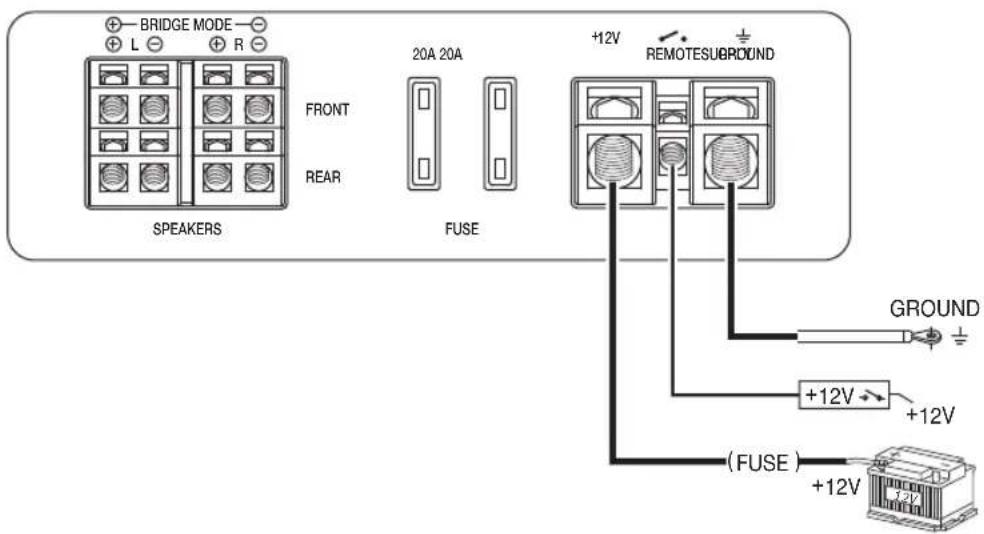
Fig. 3
GTA 470 DSP
Anschluss • Connection • Raccordement • Conexión • Ligação • Collegamento • Podłączenie • Připojení • Подключение • Racordare • Свързване • Priključak • Priklop
Fig. 4
natural_image
Two horizontal bar segments with grayscale shades and a central crosshair symbol (no text or labels)GTA 470 DSP


09/12(450 233)5101100010