
8414DWFE - Drill MAKITA - Free user manual and instructions
Find the device manual for free 8414DWFE MAKITA in PDF.
| Product Type | Cordless Impact Drill |
| Brand | Makita |
| Model | 8414DWFE |
| Power Source | 12 V DC Battery (Ni-Cd or Ni-MH) |
| No Load Speed | 0 - 300 / 0 - 550 / 0 - 1 600 min⁻¹ (3 speeds) |
| Impact Rate | 0 - 4 500 / 0 - 8 250 / 0 - 24 000 min⁻¹ |
| Drilling Capacity (Concrete) | 13 mm |
| Drilling Capacity (Steel) | 13 mm |
| Drilling Capacity (Wood) | 45 mm |
| Chuck | Keyless (Manual Tightening) |
| Torque Setting | 16 Adjustable Clutch Positions |
| Overall Length | 259 mm |
| Net Weight | 2.4 kg (with battery) |
| Side Handle | Yes, Adjustable 360° |
| Depth Rod | Adjustable Depth Stop |
| Forward/Reverse Switch | Yes, with Neutral Position |
| Operating Mode | Rotation Only, Impact, Screwdriving (Clutch) |
| Sound Pressure Level | 86 dB(A) |
| Sound Power Level | 99 dB(A) |
| Vibration (Weighted Acceleration) | 6 m/s² |
| Maintenance | Replaceable Carbon Brushes, Regular Cleaning |
| Included Accessories | Side Handle, Depth Rod, Blower Bulb (Optional) |
Frequently Asked Questions - 8414DWFE MAKITA
User questions about 8414DWFE MAKITA
0 question about this device. Answer the ones you know or ask your own.
Ask a new question about this device
Download the instructions for your Drill in PDF format for free! Find your manual 8414DWFE - MAKITA and take your electronic device back in hand. On this page are published all the documents necessary for the use of your device. 8414DWFE by MAKITA.
USER MANUAL 8414DWFE MAKITA
natural_image
Line drawing of a handheld electric drill press with attached casing (no text or symbols)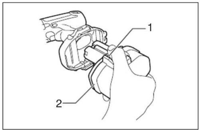
1
2
3
4
5
6
7
8
9
10
11 12
natural_image
Line drawing of a drill bit with a screw, showing mechanical components and fluid (no text or symbols)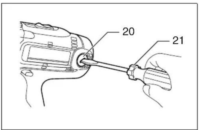
13 14
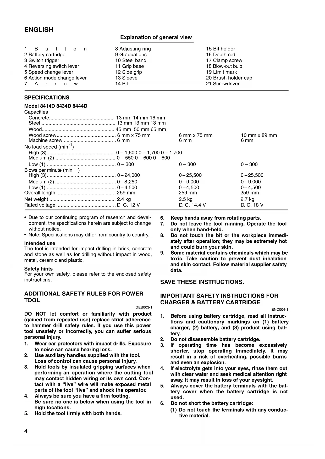
ENGLISH
| Explanation of general view | ||
| 1 Button | 8 Adjusting ring | 15 Bit holder |
| 2 Battery cartridge | 9 Graduations | 16 Depth rod |
| 3 Switch trigger | 10 Steel band | 17 Clamp screw |
| 4 Reversing switch lever | 11 Grip base | 18 Blow-out bulb |
| 5 Speed change lever | 12 Side grip | 19 Limit mark |
| 6 Action mode change lever | 13 Sleeve | 20 Brush holder cap |
| 7 Arrow | 14 Bit | 21 Screwdriver |
SPECIFICATIONS
Model 8414D 8434D 8444D
| Capacities | |||
| Concrete | 13 mm 14 mm 16 mm | ||
| Steel | 13 mm 13 mm 13 mm | ||
| Wood | 45 mm 50 mm 65 mm | ||
| Wood screw | 6 mm x 75 mm | 6 mm x 75 mm | 10 mm x 89 mm |
| Machine screw | 6 mm | 6 mm | 6 mm |
| No load speed (min ^-1 ) | |||
| High (3) | 0 - 1,600 0 - 1,700 0 - 1,700 | ||
| Medium (2) | 0 - 550 0 - 600 0 - 600 | ||
| Low (1) | 0 - 300 | 0 - 300 | 0 - 300 |
| Blows per minute (min ^-1 ) | |||
| High (3) | 0 - 24,000 | 0 - 25,500 | 0 - 25,500 |
| Medium (2) | 0 - 8,250 | 0 - 9,000 | 0 - 9,000 |
| Low (1) | 0 - 4,500 | 0 - 4,500 | 0 - 4,500 |
| Overall length | 259 mm | 259 mm | 259 mm |
| Net weight | 2.4 kg | 2.5 kg | 2.7 kg |
| Rated voltage | D. C. 12 V | D. C. 14.4 V | D. C. 18 V |
- Due to our continuing program of research and development, the specifications herein are subject to change without notice.
- Note: Specifications may differ from country to country.
Intended use
The tool is intended for impact drilling in brick, concrete and stone as well as for drilling without impact in wood, metal, ceramic and plastic.
Safety hints
For your own safety, please refer to the enclosed safety instructions.
ADDITIONAL SAFETY RULES FOR POWER TOOL
GEB003-1
DO NOT let comfort or familiarity with product (gained from repeated use) replace strict adherence to hammer drill safety rules. If you use this power tool unsafely or incorrectly, you can suffer serious personal injury.
- Wear ear protectors with impact drills. Exposure to noise can cause hearing loss.
- Use auxiliary handles supplied with the tool. Loss of control can cause personal injury.
- Hold tools by insulated gripping surfaces when performing an operation where the cutting tool may contact hidden wiring or its own cord. Contact with a "live" wire will make exposed metal parts of the tool "live" and shock the operator.
- Always be sure you have a firm footing. Be sure no one is below when using the tool in high locations.
-
Hold the tool firmly with both hands.
-
Keep hands away from rotating parts.
- Do not leave the tool running. Operate the tool only when hand-held.
- Do not touch the bit or the workpiece immediately after operation; they may be extremely hot and could burn your skin.
- Some material contains chemicals which may be toxic. Take caution to prevent dust inhalation and skin contact. Follow material supplier safety data.
SAVE THESE INSTRUCTIONS.
IMPORTANT SAFETY INSTRUCTIONS FOR CHARGER & BATTERY CARTRIDGE
ENC004-1
- Before using battery cartridge, read all instructions and cautionary markings on (1) battery charger, (2) battery, and (3) product using battery.
- Do not disassemble battery cartridge.
- If operating time has become excessively shorter, stop operating immediately. It may result in a risk of overheating, possible burns and even an explosion.
- If electrolyte gets into your eyes, rinse them out with clear water and seek medical attention right away. It may result in loss of your eyesight.
- Always cover the battery terminals with the battery cover when the battery cartridge is not used.
- Do not short the battery cartridge:
(1) Do not touch the terminals with any conductive material.
(2) Avoid storing battery cartridge in a container with other metal objects such as nails, coins, etc.
(3) Do not expose battery cartridge to water or rain.
A battery short can cause a large current flow, overheating, possible burns and even a breakdown.
- Do not store the tool and battery cartridge in locations where the temperature may reach or exceed 50^ C ( 122^ F).
- Do not incinerate the battery cartridge even if it is severely damaged or is completely worn out. The battery cartridge can explode in a fire.
- Be careful not to drop or strike battery.
SAVE THESE INSTRUCTIONS.
Tips for maintaining maximum battery life
- Charge the battery cartridge before completely discharged.
Always stop tool operation and charge the battery cartridge when you notice less tool power.
- Never recharge a fully charged battery cartridge. Overcharging shortens the battery service life.
- Charge the battery cartridge with room temperature at 10^ C – 40^ C ( 50^ F – 104^ F). Let a hot battery cartridge cool down before charging it.
- Charge the Nickel Metal Hydride battery cartridge when you do not use it for more than six months.
FUNCTIONAL DESCRIPTION
CAUTION:
- Always be sure that the tool is switched off and the battery cartridge is removed before adjusting or checking function on the tool.
Installing or removing battery cartridge (Fig. 1)
- Always switch off the tool before insertion or removal of the battery cartridge.
- To remove the battery cartridge, withdraw it from the tool while pressing the buttons on both sides of the cartridge.
- To insert the battery cartridge, align the tongue on the battery cartridge with the groove in the housing and slip it into place. Always insert it all the way until it locks in place with a little click. If not, it may accidentally fall out of the tool, causing injury to you or someone around you.
- Do not use force when inserting the battery cartridge. If the cartridge does not slide in easily, it is not being inserted correctly.
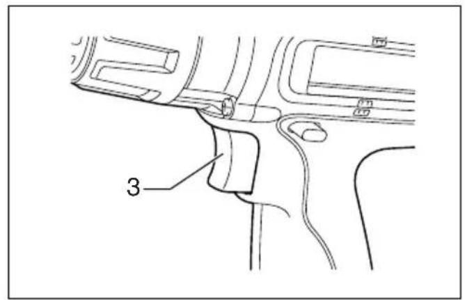
Switch action (Fig. 2)
CAUTION:
- Before inserting the battery cartridge into the tool, always check to see that the switch trigger actuates properly and returns to the "OFF" position when released.
To start the tool, simply pull the switch trigger. Tool speed is increased by increasing pressure on the switch trigger. Release the switch trigger to stop.
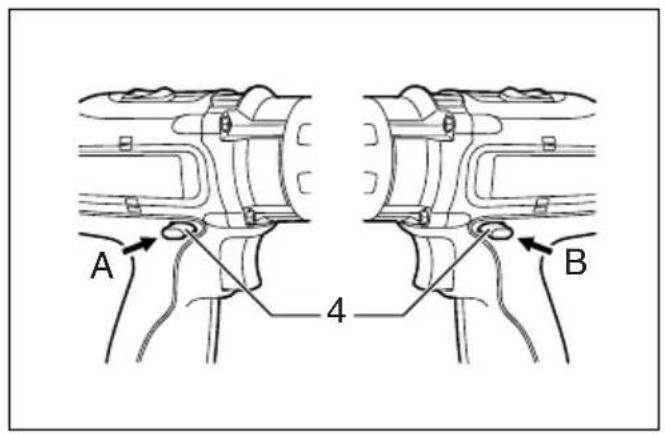
Reversing switch action (Fig. 3)
This tool has a reversing switch to change the direction of rotation. Depress the reversing switch lever from the "A" side for clockwise rotation or from the "B" side for counterclockwise rotation.
When the reversing switch lever is in the neutral position, the switch trigger cannot be pulled.
CAUTION:
- Always check the direction of rotation before operation.
- Use the reversing switch only after the tool comes to a complete stop. Changing the direction of rotation before the tool stops may damage the tool.
- When not operating the tool, always set the reversing switch lever to the neutral position.
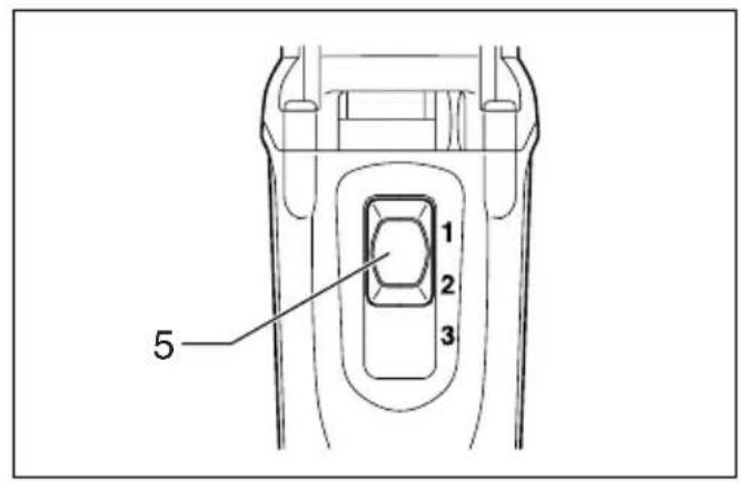
Speed change (Fig. 4)
This tool has a three-gear speed change lever. To change the speed, first switch off the tool and then slide the speed change lever to the "1" position for low speed, "2" position for medium speed or "3" position for high speed. Be sure that the speed change lever is set to the correct position before operation. Use the right speed for your job.
NOTE:
When changing the position from "1" to "3" or from "3" to "1", it may be a little difficult to slide the speed change lever. At this time, switch on and run the tool for a second at the "2" position, then stop the tool and slide to your desired position.
CAUTION:
- Always set the speed change lever fully to the correct position. If you operate the tool with the speed change lever positioned halfway between the "1" position, "2" position and "3" position, the tool may be damaged.
- Do not use the speed change lever while the tool is running. The tool may be damaged.
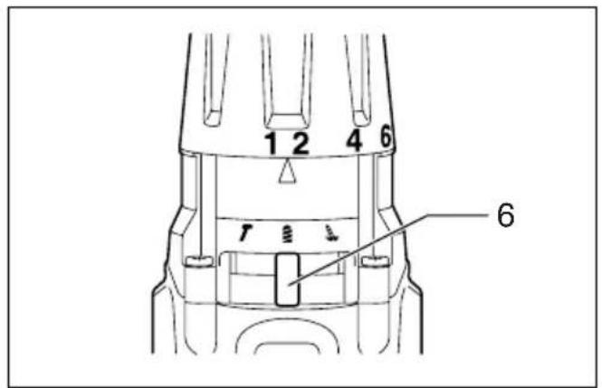
Selecting the action mode (Fig. 5)
This tool employs an action mode changing lever. Select one of the three modes suitable for your work needs by using this lever.
For rotation only, slide the lever so that it points toward the ⏻ mark on the tool body.
For rotation with hammering, slide the lever so that it points toward the mark on the tool body.
For rotation with clutch, slide the lever so that it points toward the mark on the tool body.
NOTE:
When changing the position from to, it may be a little difficult to slide the mode change lever. At this time, switch on and run the tool for a second at the position, then stop the tool and slide to your desired position.
CAUTION:
Always set the lever correctly to your desired mode mark. If you operate the tool with the lever positioned halfway between the mode marks, the tool may be damaged.
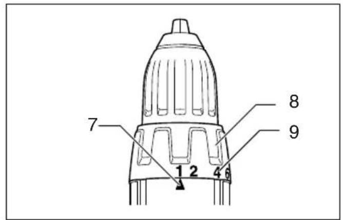
Adjusting the fastening torque (Fig. 6)
The fastening torque can be adjusted in 16 steps by turning the adjusting ring so that its graduations are aligned with the arrow on the tool body. The fastening torque is minimum when the number 1 is aligned with the arrow, and maximum when the number 16 is aligned with the arrow.
Before actual operation, drive a trial screw into your material or a piece of duplicate material to determine which torque level is required for a particular application.
ASSEMBLY
CAUTION:
- Always be sure that the tool is switched off and the battery cartridge is removed before carrying out any work on the tool.
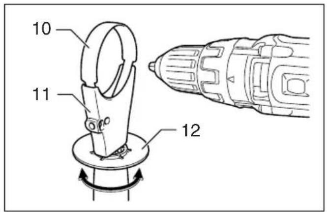
Installing side grip (auxiliary handle) (Fig. 7)
Always use the side grip to ensure operating safety. Install the side grip so that the steel band of the grip fits on the tool barrel.
Then tighten the grip by turning clockwise at the desired position. It may be swung 360^ so as to be secured at any position.
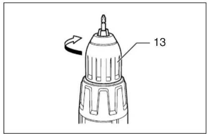
Installing or removing driver bit or drill bit
Turn the sleeve counterclockwise to open the chuck jaws. Place the bit in the chuck as far as it will go. Turn the sleeve clockwise to tighten the chuck. To remove the bit, turn the sleeve counterclockwise. (Fig. 8)
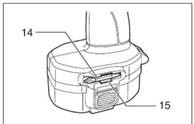
When not using the driver bit, keep it in the bit holders.
Bits 45 mm long can be kept there. (Fig. 9)
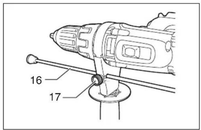
Adjustable depth rod (Fig. 10)
The adjustable depth rod is used to drill holes of uniform depth. Loosen the clamp screw, set to desired position, then tighten the clamp screw.
OPERATION
Hammer drilling operation
CAUTION:
- There is a tremendous and sudden twisting force exerted on the tool/bit at the time of hole breakthrough, when the hole becomes clogged with chips and particles, or when striking reinforcing rods embedded in the concrete. Always use the side grip (auxiliary handle) and firmly hold the tool by both side grip and switch handle during operations. Failure to do so may result in the loss of control of the tool and potentially severe injury.
First, slide the action mode change lever so that it points to the marking. The adjusting ring can be aligned in any torque levels for this operation.
Be sure to use a tungsten-carbide tipped bit.
Position the bit at the desired location for the hole, then pull the switch trigger. Do not force the tool. Light pressure gives best results. Keep the tool in position and prevent it from slipping away from the hole.
Do not apply more pressure when the hole becomes clogged with chips or particles. Instead, run the tool at an idle, then remove the bit partially from the hole. By repeating this several times, the hole will be cleaned out and normal drilling may be resumed.
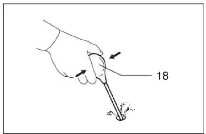
Blow-out bulb (optional accessory) (Fig. 11)
After drilling the hole, use the blow-out bulb to clean the dust out of the hole.
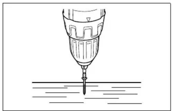
Screwdriving operation (Fig. 12)
First, slide the action mode change lever so that it points to the marking. Adjust the adjusting ring to the proper torque level for your work. Then proceed as follows.
Place the point of the driver bit in the screw head and apply pressure to the tool. Start the tool slowly and then increase the speed gradually. Release the switch trigger as soon as the clutch cuts in.
NOTE:
- Make sure that the driver bit is inserted straight in the screw head, or the screw and/or bit may be damaged.
- When driving wood screws, predrill pilot holes to make driving easier and to prevent splitting of the workpiece. See the chart.
| Nominal diameter of wood screw (mm) | Recommended size of pilot hole (mm) |
| 3.1 2.0 – 2.2 | |
| 3.5 2.2 – 2.5 | |
| 3.8 2.5 – 2.8 | |
| 4.5 2.9 – 3.2 | |
| 4.8 3.1 – 3.4 | |
| 5.1 3.3 – 3.6 | |
| 5.5 3.6 – 3.9 | |
| 5.8 4.0 – 4.2 | |
| 6.1 4.2 – 4.4 |
NOTE:
- If the tool is operated continuously until the battery cartridge has discharged, allow the tool to rest for 15 minutes before proceeding with a fresh battery.
Drilling operation
CAUTION:
- Pressing excessively on the tool will not speed up the drilling. In fact, this excessive pressure will only serve to damage the tip of your bit, decrease the tool performance and shorten the service life of the tool.
- There is a tremendous force exerted on the tool/bit at the time of hole break through. Hold the tool firmly and exert care when the bit begins to break through the workpiece.
- A stuck bit can be removed simply by setting the reversing switch to reverse rotation in order to back out. However, the tool may back out abruptly if you do not hold it firmly.
- Always secure small workpieces in a vise or similar hold-down device.
- If the tool is operated continuously until the battery cartridge has discharged, allow the tool to rest for 15 minutes before proceeding with a fresh battery.
First, slide the action mode change lever so that it points to the ⏻ marking. The adjusting ring can be aligned in any torque levels for this operation. Then proceed as follows.
Drilling in wood
When drilling in wood, the best results are obtained with wood drills equipped with a guide screw. The guide screw makes drilling easier by pulling the bit into the workpiece.
Drilling in metal
To prevent the bit from slipping when starting a hole, make an indentation with a center-punch and hammer at the point to be drilled. Place the point of the bit in the indentation and start drilling.
Use a cutting lubricant when drilling metals. The exceptions are iron and brass which should be drilled dry.
MAINTENANCE
CAUTION:
- Always be sure that the tool is switched off and the battery cartridge is removed before attempting to perform inspection or maintenance.
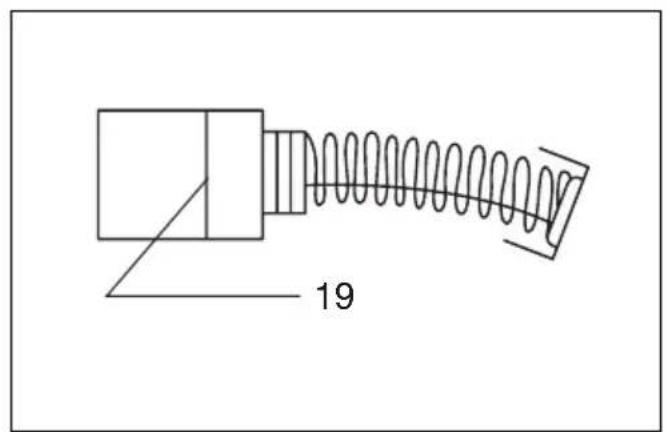
Replacing carbon brushes (Fig. 13 & 14)
Remove and check the carbon brushes regularly. Replace when they wear down to the limit mark. Keep the carbon brushes clean and free to slip in the holders. Both carbon brushes should be replaced at the same time. Use only identical carbon brushes.
Use a screwdriver to remove the brush holder caps. Take out the worn carbon brushes, insert the new ones and secure the brush holder caps.
To maintain product SAFETY and RELIABILITY, repairs, any other maintenance or adjustment should be performed by Makita Authorized or Factory Service Centres, always using Makita replacement parts.
ACCESSORIES
CAUTION:
- These accessories or attachments are recommended for use with your Makita tool specified in this manual. The use of any other accessories or attachments might present a risk of injury to persons. Only use accessory or attachment for its stated purpose.
If you need any assistance for more details regarding these accessories, ask your local Makita service center.
- Drill bits
- Hammer drill bits
- Screw bits
- Grip assembly
- Depth rod
- Blow-out bulb
- Safety goggles
- Rubber pad assembly
- Foam polishing pad
- Wool bonnet
- Various type of Makita genuine batteries and chargers
Descriptif
EC-DECLARATION OF CONFORMITY
We declare under our sole responsibility that this product is in compliance with the following standards of standardized documents, EN60745, EN55014
in accordance with Council Directives, 89/336/EEC and 98/37/EC.
FRANÇAISE
DÉCLARATION DE CONFORMITÉ CE
Michigan Drive, Tongwell, Milton Keynes,
Bucks MK15 8JD, ENGLAND
Responsible manufacturer: Produttore responsabile:
EU-DEKLARATION OM KONFORMITET
Michigan Drive, Tongwell, Milton Keynes,
Bucks MK15 8JD, ENGLAND
Fabricante responsável: Ansvarlig produsent:
Noise and Vibration of Model 8414D
The typical A-weighted noise levels are
sound pressure level: 86 dB (A)
sound power level: 99 dB (A)
- Wear ear protection. -
The typical weighted root mean square acceleration value is 6 m/s^2 .
These values have been obtained according to EN50260.
Noise and Vibration of Model 8434D
The typical A-weighted noise levels are
sound pressure level: 86 dB (A)
sound power level: 99 dB (A)
- Wear ear protection. -
The typical weighted root mean square acceleration value is 7 m/s^2 .
These values have been obtained according to EN50260.
Noise and Vibration of Model 8444D
The typical A-weighted noise levels are
sound pressure level: 86 dB (A)
sound power level: 99 dB (A)
- Wear ear protection. -
The typical weighted root mean square acceleration value is 8 m/s^2 .
These values have been obtained according to EN50260.