USER MANUAL 710DWS2-225.1001 DEXTER
natural_image
Technical line drawing of a mechanical device with no visible text or symbols
FR Ponceuse à plâtre
télescopique
ES Lijadora telescópica para paneles de yeso
PT Lixadeira telescópica para placas de gesso
IT Levigatrice telescopica per cartongesso
EL Τηλεσκοπικό τριβείο γυψοσανίδας
PL Szlifierka teleskopowa do płyt gipsowo-kartonowych
Телескопічна
UA шліфувальна машина для
гіпсокартону
RO Şlefuitor telescopic pentru gips-carton
EN Telescopic drywall sander

EAN CODE : 3276007726503 / ADEO KEY: 88962024
FR Mode d'emploi
1) BEZPIECZEŃSTWO W MIEJSCU PRACY
Please read the operating instruction carefully and observe the notes given. Use these operating instructions to familiarise yourself with the product, the proper use and the safety instructions. Keep these operating instructions in a safe place for future uses.
SYMBOLS

Read instruction manual carefully

This danger notice warns of damage to the appliance or others properties, or may cause physical injuries.

Wear safety glasses

Wear ear protection

Wear safety shoes

Wear protective gloves

Wear a dust mask

The product complies with the applicable European directives and an evaluation method of conformity for these directives was done.

Weee symbol for recycling operation.

Conformity marking that product comply with applicable Ukraine technical regulations.

Always operate with two hands

Disconnect mains plug from electrical outlet
1. INTENDED USE
Thank you for purchasing this product. Please read through these operating instructions and keep them for future reference.
This machine is intended for sanding with the rough walls and floor etc. Do not use machine attachments for works other than those for which they are designed for! All other applications are expressly ruled out.
After unwrapping the packing, make sure that the product is complete with its accessories (if any). If the product is damaged or has any defect, please do not use it and bring back it to your dealer.
If you give this tool to another people, please give him also this instruction manual.
Please note that our equipment has not been designed for use in commercial, trade or industrial applications. Our warranty will be voided if the machine is used in commercial, trade or industrial businesses or for equivalent purposes.
For safety reasons, children and young people under the age of 16, as well as people not familiar with these operating instructions, may not use this product. Persons with reduced physical or mental abilities may use the product only if they are supervised or instructed by a responsible person.
2. SAFETY INSTRUCTIONS

WARNING: Read all safety warnings, instructions, illustrations and specifications provided with this power tool. Failure to follow all instructions listed below may result in electric shock, fire and/or serious injury.
SAVE ALL WARNINGS AND INSTRUCTIONS FOR FUTURE REFERENCE.
The term "power tool" in the warnings refers to your main-operated (corded) power tool or battery-operated (cordless) power tool..
1) WORK AREA SAFETY
A. Keep work area clean and well lit. Cluttered or dark areas invite accidents.
B. Do not operate power tools in explosive atmospheres, such as in the presence of flammable liquids, gases or dust. Power tools create sparks which may ignite the dust or fumes.
C. Keep children and bystanders away while operating a power tool. Distractions can cause you to lose control.
2) ELECTRICAL SAFETY
A. Power tool plugs must match the outlet. Never modify the plug in any way. Do not use any adapter plugs with earthed (grounded) power tools. Unmodified plugs and matching outlets will reduce risk of electric shock.
B. Avoid body contact with earthed or grounded surfaces, such as pipes, radiators, ranges and refrigerators. There is an increased risk of electric shock if your body is earthed or grounded.
C. Do not expose power tools to rain or wet conditions. Water entering a power tool will increase the risk of electric shock.
D. Do not abuse the cord. Never use the cord for carrying, pulling or unplugging the power tool. Keep cord away from heat, oil, sharp edges or moving parts. Damaged or entangled cords increase the risk of electric shock.
E. When operating a power tool outdoors, use an extension cord suitable for outdoor use. Use of a cord suitable for outdoor use reduces the risk of electric shock.
F. If operating a power tool in a damp location is unavoidable, use a residual current device (RCD) protected supply. Use of an RCD reduces the risk of electric shock.
3) PERSONAL SAFETY
A. Stay alert, watch what you are doing and use common sense when operating a power tool. Do not use a power tool while you are tired or under the influence of drugs, alcohol or medication. A moment of inattention while operating power tools may result in serious personal injury.
B. Use personal protective equipment. Always wear eye protection. Protective equipment such as dust mask, non-skid safety shoes, hard hat or hearing protection used for appropriate conditions will reduce personal injuries.
C. Prevent unintentional starting. Ensure the switch is in the off-position before connecting to power source, picking up or carrying the tool. Carrying power tools with your finger on the switch or energising power tools that have the switch on invites accidents.
D. Remove any adjusting key or wrench before turning the power tool on. A wrench or a key left attached to a rotating part of the power tool may result in personal injury.
E. Do not overreach. Keep proper footing and balance at all times. This enables better control of the power tool in unexpected situations.
F. Dress properly. Do not wear loose clothing or jewellery. Keep your hair and clothing away from moving parts. Loose clothes, jewellery or long hair can be caught in moving parts.
G. If devices are provided for the connection of dust extraction and collection facilities, ensure these are connected and properly used. Use of dust collection can reduce dust-related hazards.
H. Do not let familiarity gained from frequent use of tools allow you to become complacent and ignore tool safety principles. A careless action can cause severe injury within a fraction of a second.
A. Do not force the power tool. Use the correct power tool for your application. The correct power tool will do the job better and safer at the rate for which it was designed.
B. Do not use the power tool if the switch does not turn it on and off. Any power tool that cannot be controlled with the switch is dangerous and must be repaired.
C. Disconnect the plug from the power source and/or remove the battery pack, if detachable, from the power tool before making any adjustments, changing accessories, or storing power tools. Such preventive safety measures reduce the risk of starting the power tool accidentally.
D. Store idle power tools out of the reach of children and do not allow persons unfamiliar with the power tool or these instructions to operate the power tool. Power tools are dangerous in the hands of untrained users.
E. Maintain power tools and accessories. Check for misalignment or binding of moving parts, breakage of parts and any other condition that may affect the power tool's operation. If damaged, have the power tool repaired before use. Many accidents are caused by poorly maintained power tools.
F. Keep cutting tools sharp and clean. Properly maintained cutting tools with sharp cutting edges are less likely to bind and are easier to control.
G. Use the power tool, accessories and tool bits etc. in accordance with these instructions, taking into account the working conditions and the work to be performed. Use of the power tool for operations different from those intended could result in a hazardous situation.
H. Keep handles and grasping surfaces dry, clean and free from oil and grease. Slippery handles and grasping surfaces do not allow for safe handling and control of the tool in unexpected situations.
5) SERVICE
A. Have your power tool serviced by a qualified repair person using only identical replacement parts. This will ensure that the safety of the power tool is maintained.
SAFETY WARNINGS COMMON FOR SANDING OPERATIONS:
A) THIS POWER TOOL IS INTENDED TO FUNCTION AS A SANDER. READ ALL SAFETY WARNINGS, INSTRUCTIONS, ILLUSTRATIONS AND SPECIFICATIONS PROVIDED WITH THIS POWER TOOL. FAILURE TO FOLLOW ALL INSTRUCTIONS LISTED BELOW MAY RESULT IN ELECTRIC SHOCK, FIRE AND/OR SERIOUS INJURY.
B) OPERATIONS SUCH AS GRINDING, WIRE BRUSHING, POLISHING, HOLE CUTTING OR CUTTING-OFF ARE NOT TO BE PERFORMED WITH THIS POWER TOOL. OPERATIONS FOR WHICH THE POWER TOOL WAS NOT DESIGNED MAY CREATE A HAZARD AND CAUSE PERSONAL INJURY.
C) DO NOT CONVERT THIS POWER TOOL TO OPERATE IN A WAY WHICH IS NOT SPECIFICALLY DESIGNED AND SPECIFIED BY THE TOOL MANUFACTURER. SUCH A CONVERSION MAY RESULT IN A LOSS OF CONTROL AND CAUSE SERIOUS PERSONAL INJURY.
D) DO NOT USE ACCESSORIES WHICH ARE NOT SPECIFICALLY DESIGNED AND SPECIFIED BY THE TOOL MANUFACTURER. JUST BECAUSE THE ACCESSORY CAN BE ATTACHED TO YOUR POWER TOOL, IT DOES NOT ASSURE SAFE OPERATION.
E) THE RATED SPEED OF THE ACCESSORY MUST BE AT LEAST EQUAL TO THE MAXIMUM SPEED MARKED ON THE POWER TOOL. ACCESSORIES RUNNING FASTER THAN THEIR RATED SPEED CAN BREAK AND FLY APART.
F) THE OUTSIDE DIAMETER AND THE THICKNESS OF YOUR ACCESSORY MUST BE WITHIN THE CAPACITY RATING OF YOUR POWER TOOL. INCORRECTLY SIZED ACCESSORIES CANNOT BE ADEQUATELY GUARDED OR CONTROLLED.
G) THE DIMENSIONS OF THE ACCESSORY MOUNTING MUST FIT THE DIMENSIONS OF THE MOUNTING HARDWARE OF THE POWER TOOL. ACCESSORIES THAT DO NOT MATCH THE MOUNTING HARDWARE OF THE POWER TOOL WILL RUN OUT OF BALANCE, VIBRATE EXCESSIVELY AND MAY CAUSE LOSS OF CONTROL.
H) DO NOT USE A DAMAGED ACCESSORY. BEFORE EACH USE INSPECT THE ACCESSORY SUCH AS ABRASIVE WHEELS FOR CHIPS AND CRACKS, BACKING PAD FOR CRACKS, TEAR OR EXCESS WEAR, WIRE BRUSH FOR LOOSE OR CRACKED WIRES. IF POWER TOOL OR ACCESSORY IS DROPPED, INSPECT FOR DAMAGE OR INSTALL AN UNDAMAGED ACCESSORY. AFTER INSPECTING AND INSTALLING AN ACCESSORY, POSITION YOURSELF AND BYSTANDERS AWAY FROM THE PLANE OF THE ROTATING ACCESSORY AND RUN THE POWER TOOL AT MAXIMUM NO-LOAD SPEED FOR ONE MINUTE. DAMAGED ACCESSORIES WILL NORMALLY BREAK APART DURING THIS TEST TIME.
I) WEAR PERSONAL PROTECTIVE EQUIPMENT. DEPENDING ON APPLICATION, USE FACE SHIELD, SAFETY GOGGLES OR SAFETY GLASSES. AS APPROPRIATE, WEAR DUST MASK, HEARING PROTECTORS, GLOVES AND WORKSHOP APRON CAPABLE OF STOPPING SMALL ABRASIVE OR WORKPIECE FRAGMENTS. THE EYE PROTECTION
MUST BE CAPABLE OF STOPPING FLYING DEBRIS GENERATED BY VARIOUS APPLICATIONS. THE DUST MASK OR RESPIRATOR MUST BE CAPABLE OF FILTRATING PARTICLES GENERATED BY THE PARTICULAR APPLICATION. PROLONGED EXPOSURE TO HIGH INTENSITY NOISE MAY CAUSE HEARING LOSS.
J) KEEP BYSTANDERS A SAFE DISTANCE AWAY FROM WORK AREA. ANYONE ENTERING THE WORK AREA MUST WEAR PERSONAL PROTECTIVE EQUIPMENT. FRAGMENTS OF WORKPIECE OR OF A BROKEN ACCESSORY MAY FLY AWAY AND CAUSE INJURY BEYOND IMMEDIATE AREA OF OPERATION.
K) POSITION THE CORD CLEAR OF THE SPINNING ACCESSORY. IF YOU LOSE CONTROL, THE CORD MAY BE CUT OR SNAGGED AND YOUR HAND OR ARM MAY BE PULLED INTO THE SPINNING ACCESSORY.
L) NEVER LAY THE POWER TOOL DOWN UNTIL THE ACCESSORY HAS COME TO A COMPLETE STOP. THE SPINNING ACCESSORY MAY GRAB THE SURFACE AND PULL THE POWER TOOL OUT OF YOUR CONTROL.
M) DO NOT RUN THE POWER TOOL WHILE CARRYING IT AT YOUR SIDE. ACCIDENTAL CONTACT WITH THE SPINNING ACCESSORY COULD SNAG YOUR CLOTHING, PULLING THE ACCESSORY INTO YOUR BODY.
N) REGULARLY CLEAN THE POWER TOOL'S AIR VENTS. THE MOTOR'S FAN WILL DRAW THE DUST INSIDE THE HOUSING AND EXCESSIVE ACCUMULATION OF POWDERED METAL MAY CAUSE ELECTRICAL HAZARDS.
0) DO NOT OPERATE THE POWER TOOL NEAR FLAMMABLE MATERIALS. SPARKS COULD IGNITE THESE MATERIALS.
P) DO NOT USE ACCESSORIES THAT REQUIRE LIQUID COOLANTS. USING WATER OR OTHER LIQUID COOLANTS MAY RESULT IN ELECTROCUTION OR SHOCK.
2. SAFETY INSTRUCTIONS
FURTHER SAFETY INSTRUCTIONS FOR ALL OPERATIONS
Kickback is a sudden reaction to a pinched or snagged rotating wheel, backing pad, brush or any other accessory. Pinching or snagging causes rapid stalling of the rotating accessory which in turn causes the uncontrolled power tool to be forced in the direction opposite of the accessory's rotation at the point of the binding.
For example, if an abrasive wheel is snagged or pinched by the workpiece, the edge of the wheel that is entering into the pinch point can dig into the surface of the material causing the wheel to climb out or kick out. The wheel may either jump toward or away from the operator, depending on direction of the wheel's movement at the point of pinching. Abrasive wheels may also break under these conditions.
Kickback is the result of power tool misuse and/or incorrect operating procedures or conditions and can be avoided by taking proper precautions as given below.
A. Maintain a firm grip with both hands on the power tool and position your body and arms to allow you to resist kickback forces. Always use auxiliary handle, if provided, for maximum control over kickback or torque reaction during start-up. The operator can control torque reactions or kickback forces, if proper precautions are taken.
B. Never place your hand near the rotating accessory. Accessory may kickback over your hand.
C. Do not position your body in the area where power tool will move if kickback occurs. Kickback will propel the tool in direction opposite to the wheel's movement at the point of snagging.
D. Use special care when working corners, sharp edges etc. Avoid bouncing and snagging the accessory. Corners, sharp edges or bouncing have a tendency to snag the rotating accessory and cause loss of control or kickback.
E. Do not attach a saw chain woodcarving blade, segmented diamond wheel with a peripheral gap greater than 10 mm or toothed saw blade. Such blades create frequent kickback and loss of control.
Safety Warnings Specific for Sanding Operations:
A. Use proper sized sanding disc paper. Follow manufacturers recommendations, when selecting sanding paper. Larger sanding paper extending too far beyond the sanding pad presents a laceration hazard and may cause snagging, tearing of the disc or kickback.
Precautions on using drywall sander
Attention! You must abide by the following basic safety measures against electrical shocks, injuries and the danger of fire when using electric tools. Read and abide by these instructions before you start to use any tools. These instructions must be kept in a safe place.
- The equipment must never be used in surroundings where an explosive atmosphere exists.
- Do not let the cable touch any parts of your body.
- Only use the extension cable approved for use in the working area.
- Do not force the machine for unsuitable work, for example, rough grinding, brushing, etc. Otherwise, dangers and harms will be caused.
- Only use identical replacement parts when servicing. Otherwise, risk-free operation can't be guaranteed
- Do not use damaged accessories. Before use, always check whether the accessories are nicked or cracked. For example, please check the support plate is not cracked. Ensure everybody to be out of the machine's rotation area and run the machine at max. speed for one minute, which can fully test the accessories.
- Do not put down the machine when it isn't stopped completely. Otherwise, you will loss control to the machine.
- Cleaning the dust vent on your machine in regular.
- When working, control the machine firmly with both hands to ensure safe operation.
- When sanding, do not use too big sandpaper. The sand paper beyond the sanding block leads to risk of cutting and injury and cause stuck as well.
- The machine can be connected to one extension tubes at most.
- We recommend that you always wear industrial safety gloves and safety goggles when working with the drywall sander.
- Wearing close-fitting clothes is mandatory.
- Wear protection mask to protect you from hazardous dusts and choose suitable vacuum cleaner.
3. DESCRIPTION
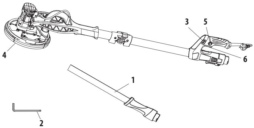
1 Auxiliary handle
2 Wrench
3 Speed controller
4 Combo guard for grinding
5 Lock-on button
6 Switch trigger
4. TECHNICAL DATA
| Model | 710DWS2-225.1001 |
| Rated voltage: | 220-240 V~ |
| Rated speed: | 800-1800 /min |
| Rated Power : | 710w |
| Grinding pad diameter | 215mm |
| Sandpaper diameter | 225mm |
| Weight | 3.6 kg |
| Protection dass | II |
| Noise emission value | L_PA=85.2dB(A),L_WA=93.2dB (A) |
| Uncertainty | K=3dB(A) |
| Vibration emission value | <2.5 m/s2 |
| Uncertainty | K.<1.5m/s2 |
NOTE: The declared vibration total value(s) and the declared noise emission value(s) have been measured in accordance with a standard test method and may be used for comparing one tool with another;
The declared vibration total value(s) and the declared noise emission value(s) may also be used in a preliminary assessment of exposure.
WARNING! The vibration and noise emissions during actual use of the power tool can differ from the declared values depending on the ways in which the tool is used especially what kind of workpiece is processed;
The emissions need to identify safety measures to protect the operator that are based on an estimation of exposure in the actual conditions of use (taking account of all parts of the operating cycle such as the times when the tool is switched off and when it is running idle in addition to the trigger time).
WARNING! The grinding thin sheets of metal or other easily vibrating structures with a large surface can result in a total noise emission much higher (up to 15 dB) than the declared noise emission values. Such workpieces should as far as possible be prevented from emitting sound by suitable measures such as the application of heavy flexible damping mats. The increased noise emission is also to be considered for both the risk assessment of noise exposure and selecting adequate hearing protection
WARNING! Recommendation for the operator to wear hearing protection.
5. BEFORE USE

DANGER! Risk of injury due to electric shock.
Warning! Do not plug in before installation is fully completed!
SAVE ALL WARNINGS AND INSTRUCTIONS FOR FUTURE REFERENCE.
ASSEMBLY AND ADJUSTMENT

NOTE: Prior to assembly and adjustment always unplug the tool.
- Fully unfold the upper shaft in the direction against the lower shaft.
- Secure the connection with the locking device.
- Use the extension shaft according to the intended operation for higher work surface.
- Loosen the sleeve on the dust extraction outlet of the upper extension shaft. Do not remove the sleeve from the outlet.
- Align the rear handle with the main handle and insert the sleeve on the extension shaft into the outlet with a twist motion all the way to the stop.
- Adjust the length of the extension shaft if necessary. Pay attention to the marking «Max 1.65m» on the extension shaft. Tighten the sleeve after assembling/adjusting the extension shaft.
- Align the hole pattern of the sanding paper with the one in the base plate before attaching the sanding paper to the plate to ensure efficient dust extraction and a satisfactory result.
- Slightly press the sanding paper to fix it to the base plate.
- Insert the vacuum hose connector into the dust extraction outlet all the way to stop.
- Secure the connection by tightening the sleeve on the outlet afterward.
- Attach a dust extraction device e.g. a suitable vacuum cleaner to the vacuum adaptor. Loosen the sleeve on the dust extraction outlet, hold the handles and pull the connector out of the outlet to remove the vacuum hose from the product.
- Ensure the work surface is free of obstacles like nails or screws before operation. Remove them if required.
6. USE
- Hold the product with one hand on the main handle and with the other hand on gripping surface.
- Hold the product with one hand on the main handle and with the other hand on the rear handle when the extension shaft is assembled.
- Switch the product ON by pressing the trigger and wait until it runs at full speed before placing it on the work surface.
- To switch OFF the product, just release the trigger
- To lock the product on ON mode, press the orange button located above the trigger when the product is running.
- To increase the rotate speed, press the + button located on the main handle. To decrease the rotate speed, press the - button located on the main handle.
- Keep the base plate as parallel to the work surface as possible.
- Ensure that the machine head is in contact with the work surface.
- Move the product back and forth with slow even speed.
- Only apply as much pressure as necessary to keep the product at on the work surface. Higher pressure will not increase but lower the performance of the product and leads to uneven results.
- Keep the product moving at all times, do not stop in one position to avoid grooves.
- Lift the product from the work surface before switching it off.
7. MAINTENANCE

DANGER! Risk of injury due to electric shock.

Warning! Always remove the plug from the socket before servicing, cleaning or storage.
- Keep the product clean. Remove debris from it after each use and before storage.
- Regular and proper cleaning will help ensure safe use and prolong the life of the product.
- Inspect the product before each use for worn and damaged parts. Do not operate it if you find broken and worn parts.
- Clean the product with a dry doth. Use a brush for areas that are hard to reach.
- In particular clean the air vents after every use with a cloth and brush.
- Remove stubborn dirt with high pressure air (max. 3 bar).
- Check for worn or damaged parts. Replace worn parts as necessary or contact an authorized service center for repair before using the product again.
- Before and after each use, check the product and accessories (or attachments) for wear and damage. If required, exchange them for new ones as described in this instruction manual. Observe the technical requirements.
- This product does not contain any parts that can be repaired by the consumer. Contact an authorized service center or a similarly qualified person to have it checked and repaired.
- If the replacement of the supply cord is necessary, this has to be done by the manufacturer or his agent in order to avoid a safety hazard. If the carbon brushes need to be replaced, have this done by a qualified repair person (always replace the two brushes at the same time).
- Hex key is used to disassemble the hex screw on sanding pad.
8. TROUBLE SHOOTING

DANGER! Risk of injury due to electric shock.

Warning! Before any trouble shooting, remove the plug from the socket.
| Problems | Probable causes | Corrective action |
| Product doesn’t start | Not connected to power supply Connect | Connect to power supply |
| Power cord or plug is defective | Check by a specialist electrician |
| Other electrical defect to the product | Check by a specialist electrician |
| Product does not reach full power | Extension cord not suitable for operation with this product | Use a proper extension cord |
| Power source (e.g.generator) has too low voltage | Connect to another power source |
| Air vents are blocked | Clean the air vents |
| Unsatisfactory result | Sanding paper is worn | Replace with new one |
| Sanding paper not suitable for work surface material | Use proper sanding paper |
| Strong dust formation | Brush-type skirt worn out | Have the brush-type skirt replaced |
| Dust extraction system not connected/switch on | Connect to/switch on dust extraction system |
9. RECYCLING

The packaging consists of environmentally friendly material. It can be disposed of in the local recycling containers.

CAUTION! This product has been marked with a symbol relating to removing electric and electronic waste. This means that this product shall not be discarded with household waste but that it shall be returned to a collection system which conforms to the European WEEE Directive. Contact your local authorities or stocks for advice on recycling. It will then be recycled or dismantled in order to reduce the impact on the environment. Electric and electronic equipment can be hazardous for the environment and for human health since they contain hazardous substances.
ENVIRONMENTAL PROTECTION
Waste electrical products must not be disposed of with household waste. Please recycle where facilities exist. Check with your local authorities or retailer for recycling advice. It will then be recycled or dismantled in order to reduce the impact on the environment.
10. STORAGE AND TRANSPORTATION
STORAGE
Always store the product in a place that is inaccessible to children. The ideal storage temperature is between 10^ C and 30^ C.
We recommend using the original package for storage or covering the angle grinder with a suitable cloth or enclosure to protect it against dust.
TRANSPORTATION
Switch the product off.
Protect the angle grinder from any heavy impact or strong vibrations which may occur during transportation in vehicles.
Secure the angle grinder to prevent it from slipping or falling over.
11. WARRANTY
PREFACE
Thank you for choosing this product. Upon designing and manufacturing our products, we place all of our efforts into ensuring an excellent quality that meets the needs of the users.
IMPORTANT! PLEASE READ THIS MANUAL BEFORE USING THIS PRODUCT, FOLLOW THE BASIC SAFETY WARNINGS WITHIN, AND KEEP IT CAREFULLY.
As soon as you open the packaging, we recommend that you check to ensure that all elements required for assembly of the product have been included.
If the product is damaged or has some defects, please do not use it, and bring it back to the nearest store.
This product is intended for outdoor use only, and must not be used inside a building under any circumstances.
This product can be placed inside a building only after having rested for two hours after the last use.
We thank you for your business and hope that you will be totally satisfied upon using our product.
We will be happy to receive all of your remarks on our online store web site.
Warranty
DEXTER products are designed based on the most rigorous quality standards for products intended for the general public.
The tool is covered with a warranty of 5 years starting from the date of purchase. This warranty covers all manufacturing or material defects.
In the event of a breakdown, please refer first to the troubleshooting page (problems and solutions) in the brochure; if the problem persists, please check with the nearest store.
Your store shall spare no effort in resolving the issue.
Repairs and change of parts do not extend the duration of the initial warranty.
Breakdowns resulting from normal wear and tear or from improper use of the product are not covered by the warranty. This includes, among others, the switches, the safety circuit breaker and the motors, in case of wear.
Please note that there are specific warranty terms for certain countries.
In case of doubt, please check with your point of sale.
For claims relating to the warranty to be taken into account, the following is required:
• Providing proof of purchase
- That no repairs and/or change of parts have been performed by a third party.
- That the issue is not a matter of normal wear and tear.
- That required maintenance and repair works have been performed correctly.
- That no deterioration has taken place as a result of incorrect setting of the carburetor.
- That there has been no forcing, improper handling, unauthorised use, or accidents
- That no deterioration has taken place due to overheating, resulting from clogging of the ventilator block.
- That no work has been done on the product by an unskilled person, and no incorrect repairs have been attempted.
- That the tool has never been disassembled or opened.
- That the tool has never been in a wet environment (dew, rain, submerged in water...)
- That no incorrect parts have been used, parts not made by DEXTER, whereas they prove to be the cause of deterioration
- That the tool has not been used improperly (overloading the tool, or use of non-approved accessories).
- That no damage has resulted from external causes, or foreign bodies such as sand or stones.
- That no damage has resulted from non-compliance with safety recommendations and use instructions.
The product must be used under normal usage circumstances, and for non-professional purposes. Therefore, excluded from this warranty are products used by landscaping companies, local authorities, as well as companies offering paid rentals or free loaning of equipment.
- EXPLODED VIEW WITH PART LIST
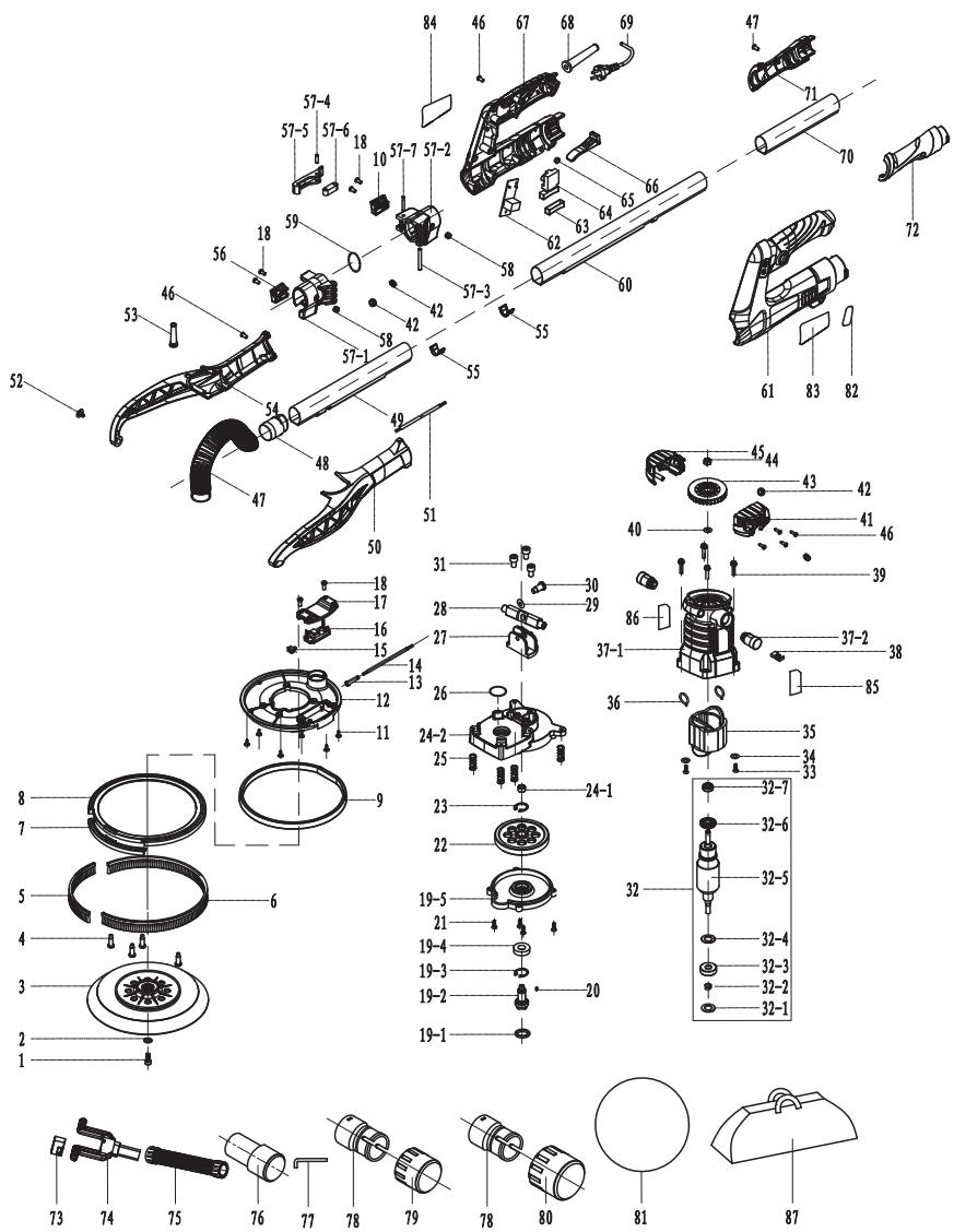
| N° | DESCRIPTION | QTY |
| 1 | Screw M6*14 | 1 |
| 2 | Washer φ6 | 1 |
| 3 | Sander pad φ215 | 1 |
| 4 | Shaft | 4 |
| 5 | Curved short brush h22*180mm | 1 |
| 6 | Curved long brush h22*600mm | 1 |
| 7 | Lateral circle | 1 |
| 8 | Brush holder | 1 |
| 9 | Lamp shade assembly KU630 | 1 |
| 10 | Rear-hinged clamp plate | 1 |
| 11 | Cross cushion screw ST4*12 | 5 |
| 12 | Disc | 1 |
| 13 | Sheath | 1 |
| 14 | Headless line SG dedicated H05VV-F-2*0.75*0.23M (open end 35/15mm) | 1 |
| 15 | Small switch | 1 |
| 16 | PCBA_LED | 1 |
| 17 | LED circuit board cover | 1 |
| N° | DESCRIPTION | QTY |
| 18 | Slotted self tapping screws | 8 |
| 19 | Large end cap assembly |
| 19-1 | Skeleton oil seal 24 × 17.3 × 3 | 1 |
| 19-2 | Output shaft R7231 | 1 |
| 19-3 | Ring 22 | 1 |
| 19-4 | 6900 2RS Bearings | 1 |
| 19-5 | Large end cover seiko | 1 |
| 20 | Flat Pin 3*8 | 1 |
| 21 | Cross pan head triangular tapping screw Black M4*16 | 4 |
| 22 | Bull wheel | 1 |
| 23 | Shaft clasp 10 | 1 |
| 24 | Gear box |
| 24-1 | Copper bushing | 1 |
| 24-2 | Head shell seiko | 1 |
| 25 | Spring R7203 | 4 |
| 26 | O-ring 25*22*1.5 | 1 |
| 27 | Rotating base | 1 |
| 28 | A movable pole | 1 |
| 29 | Butterfly gasket 18 × 9.2 × 0.45 | 1 |
| 30 | M6 screw | 1 |
| 31 | Cross pan head triangular tapping screw Black M5*16 | 3 |
| 32 | Rotor assembly |
| 32-1 | Wool pad 11* 17.5*2 | 1 |
| 32-2 | Rotor spring HL600 ( 6* 1*0.5 ) | 1 |
| 32-3 | Bearing 608 - Black rubber cap 608 | 1 |
| 32-4 | Dustproof iron sheet (608) 608 | 1 |
| 32-5 | Rotor | 1 |
| 32-6 | Dust ring | 1 |
| 32-7 | Bearing 696 (iron cap) 696 | 1 |
| 33 | ST2.9*13 Screw | 2 |
| 34 | Gasket 8.5* 3.2*1 | 2 |
| 35 | Stator | 1 |
| 36 | Tension spring (0.6-100#) | 2 |
| 37 | Housing assembly |
| 37-1 | Machine casing | 1 |
| 37-2 | Brush grip and cover | 2 |
| 38 | Carbon brush 6*9*14.8 (H94) | 2 |
| N° | DESCRIPTION | QTY |
| 39 | Cross pan head triangular tapping screw Black M4*20 | 4 |
| 40 | Washer 6*10*1 | 1 |
| 41 | Left rear shield | 1 |
| 42 | Double-sided sheath R7233 | 4 |
| 43 | Fan blade | 1 |
| 44 | M6 nut Thickness 4 | 1 |
| 45 | Right rear shield | 1 |
| 46 | Cross recessed pan head tapping screw ST4*16 | 26 |
| 47 | 460 double conductor hose | 1 |
| 48 | Hose connector KU630 | 1 |
| 49 | Front double channel aluminum tube Long 246 | 1 |
| 50 | Left side support R7203 | 1 |
| 51 | Headless wire | 1 |
| 52 | Combination screw with pad (white) M4*8 | 2 |
| 53 | SG sheath SG | 1 |
| 54 | Right side support R7203 | 1 |
| 55 | Bushing | 2 |
| 56 | Front-hinged clamp plate | 1 |
| 57 | Front and rear hinged sleeve assembly |
| 57-1 | Front hinge bushing | 1 |
| 57-2 | Rear hinged bushing | 1 |
| 57-3 | Round pin 5*45 | 1 |
| 57-4 | Round pin 5*16.8 | 1 |
| 57-5 | Wrench | 1 |
| 57-6 | Supporting arm 10×10×32 | 1 |
| 57-7 | Round pin 5*30 | 1 |
| 58 | Willow nail 5*10 | 2 |
| 59 | O-ring 35*3.5 | 1 |
| 60 | Rear dual channel aluminum tube Long 553 | 1 |
| 61 | Left master handle | 1 |
| 62 | Circuit board + governor HL7600 | 1 |
| 63 | Switch sheath | 1 |
| 64 | Switch KR82 | 1 |
| 65 | Self-locking sheath | 1 |
| 66 | Locking wrench (main handle) | 1 |
| 67 | Right master handle | 1 |
| N° | DESCRIPTION | QTY |
| 68 | Cable jacket (small hole) | 1 |
| 69 | Power cord H05VV-F-2*0.75*4.7M | 1 |
| 70 | Single channel aluminum tube Long 500 | 1 |
| 71 | Right auxiliary handle | 1 |
| 72 | Left auxiliary handle | 1 |
| 73 | Lock ring | 1 |
| 74 | Protection coupler | 1 |
| 75 | 4.8m telescopic tube | 1 |
| 76 | Adaptor (φ35) Black | 1 |
| 77 | Wrench | 1 |
| 78 | Hose connector (black) | 2 |
| 79 | 47 Adaptor | 1 |
| 80 | 57 Adaptor | 1 |
| 81 | Sander net paper 1*P180+1*P240 |
| 82 | Speed label | 1 |
| 83 | Handle label | 1 |
| 84 | Rating label | 1 |
| 85 | Housing label | 1 |
| 86 | Housing RL | 1 |
| 87 | Bag | 1 |
88962024
Name and address of the manufacturer or his authorised representative|Nom et adresse du fabricant ou de son mandataire|Nombre y dirección del fabricante o de su representante autorizado|Nome e endereço do fabricante ou do seu representante autorizado|
ADEO Services, 135 Rue Sadi Carnot - CS 00001 59790 RONCHIN - France
This declaration of conformity is issued under the sole responsibility of the manufacturer|La présente déclaration de conformité est établie sous la seule responsabilité du fabricant|La presente declaración de conformidad se expide bajo la exclusiva responsabilidad del fabricante|Esta declaração de conformidade é emitida sob a exclusiva responsabilidade do fabricante.|
Object of the declaration|Objet de la déclaration|Objeto de la declaración|Objeto da declaração|
88962024 - EAN Code: 3276007726503
Industrial Type Design Reference: 710DWS2-225.1001
DEXTER
Traceability number:SN 1105753001XX DDMMYY NN PPPPPP
The object of the declaration described above is in conformity with the relevant Union harmonization legislation|L'objet de la déclaration décrit ci-dessus est conforme à la législation d'harmonisation de l'union applicable|El objeto de la declaración descrita anteriormente es conforme a la legislación de armonización pertinente de la Unión|O objeto da declaração acima descrita está em conformidade com a legislação de harmonização da União aplicável:|
References to the relevant harmonised standards used or references to the specifications in relation to which conformity is declared|Références des normes harmonisées pertinentes appliquées ou des spécifications par rapport auxquelles la conformité est déclarée|Referencias a las normas armonizadas pertinentes utilizadas, o referencias a las especificaciones respecto a las cuales se declara la conformidad|Referências às normas harmonizadas pertinentes utilizadas ou referências às especificações para as quais a conformidade é declarada|
When applicable, the name and number of notified body number|Le cas échéant, le nom et le numérp de l'organisme notifié|Cuando corresponda * el nombre y número de laboratorio notificado que haya emitido la certificación y la referencia al documento|Quando aplicável * o nome e número do laboratório notificado que emitiu a certificação e a referência ao documento|
2006 42 EC MACHINE
machinery|Machines|máquinas |máquinas|
EN 62841-1:2015+A11:2022
EN IEC 62841-2-3:2021+A11:2021
2014 30 EU EMC
Electromagnetic compatibility|compatibilité
électromagnétique|compatibilidade electromagnética |compatibilidade eletromagnética |
EN IEC 55014-1: 2021
EN IEC 55014-2: 2021
EN IEC 61000-3-2: 2019+A1:2021
EN 61000-3-3: 2013+ A1:2019+A2:2021
2011 65 EU RoHS
International Project Quality Leader
Ronchin France
30/04/2024

Modello di prodotto/prodotto|Model produktu/produkt|Movtélo προϊόντος/Προϊόν:|Modelul de produs/produsul:|
88962024
La presente dichiarazione di conformità è rilasciata sotto la responsabilità esclusiva del fabbricante|Niniejsza deklaracja zgodności wydana zostaje na wyłączną odpowiedzialność producenta.|Επιωνυμία και διεύθυνση του κατασκευαστή ή του εξουσιοδοτημένου αντιπροσώτου του|Denumirea și adresa producătorului sau a reprezentantului său autorizat:|
ADEO Services, 135 Rue Sadi Carnot - CS 00001 59790 RONCHIN - France
La presente dichiarazione di conformità è rilasciata sotto la responsabilità esclusiva del fabbricante|Niniejsza deklaracja zgodności wydana zostaje na wyłączną odpowiedzialność producenta.|H
пароύσα δήλωση συμμόρφωσης εκδίδεται με αποκλειστική ευθύνη του κατασκευαστή|Declarația de conformitate este emisă pe răspunderea exclusivă a producătorului|
88962024 - EAN Code: 3276007726503
Industrial Type Design Reference: 710DWS2-225.1001
DEXTER
Traceability number:SN 1105753001XX DDMMYY NN PPPPPP
L'oggetto della dichiarazione di cui sopra è conforme alla pertinente normativa di armonizzazione dell'Unione|Wymieniony powyżej przedmiot niniejszej deklaraci jest zgodny z odnośnymi wymaganiami unijnego prawodawstwa harmonizacyjnego|O στόχος της δήλωσης που περιγράφεται παραπάνω είναι σύμφωνος με τη σχετική ενωσιακή νομοθεσία εναρμόνισης;|Obiectul declarației descris mai sus este în conformitate cu legislația comunitară relevantă de armonizare a Uniunii|
Riferimenti alle pertinenti norme armonizzate utilizzate o alle specifiche in relazione alle quali è dichiarata la conformità|Odolania do odnošnych norm zharmonizowanych, które zastosowano, lub do specyfikacji, od ondiensienu do których deklarowana jest zgodnosć|Μνεία των σχετικών εναρμονισμένων προτύπων που χρησιμοποιούνται ή μνεία των προδιαγραφών σε σχέση με τις οπολε δηλώνεται η συμμόφωση|Referintεle standardelor armonizate relevante folosite sau referințele specificațiilor In legătură cu care se declară conformitatea:]
Dove applicabile * il nome e il numero del laboratorio notificato che ha rilasciato la certificazione e il riferimento al documento|W stosownych przypadkach * notyfikowana nazwa i numer laboratorium, które wydało certyfikat oraz odniesienie do dokumentu|Otpon iαχύει * to γνωστοποιημένο όνομα και τον αριθμό του εργαστηρίου που εξέβωσε την πιστοποίηση και την αναφορά στο έγγραφο|Unde este cazul * numele și numárul de laborator notificat care a eliberat certificarea și trimiterea la document|
2006_42_EC_MACHINE EN 62841-1:2015+A11:2022
macchine|maszyn| σχετικά με τα μηχανήματα|echipamentele tehnice| EN IEC 62841-2-3:2021+A11:2021
2014_30_EU_EMC EN IEC 55014-1: 2021
compatibilità elettromagnetica|kompatybilności elektromagnetycznej EN IEC 55014-2: 2021
|ηλεκτρομαγνητική συμβατότητα|compatibilitatea electromagneticä| EN IEC 61000-3-2: 2019+A1:2021
EN 61000-3-3: 2013+A1:2019+A2:2021
2011_65_EU_RoHS
Restrizione di sostanze pericolose nelle apparecchiature elettriche|Ograniczenie niebezpiecznych substancji w sprzęcie elektrycznym|Περιορισμός επικίνδυνων ουσιών σε ηλεκτρικό εξοπλισμό|Restrictionarea substanțelor periculoase în echipamentele electrice|
Directive (EU) 2015/863
EN IEC 63000:2018
Compilato, firmato in vece e per conto di|Opracowano, podpisano w imieniu|Συντάχθηκε, υπογραφή για και εξ ονόματος|Compilat, semnat de şi în numele|
natural_image
Illustration of a globe with multiple flags flying around it, no text or symbols present.


PAP

Made in China 2024
** Garantie 5 ans / 5 años de garantía / Garantia de 5 anos / Garanzia 5 Anni / Εγγύηση 5 ετών / Gwarancja 5-letnia /Γαραντία 5 років / Garanție 5 ani / 5-year guarantee
ADEO Services - 135 Rue Sadi Carnot - CS 00001
59790 RONCHIN - France
Imported by Adeo South Africa (PTY) LTD T/A Leroy Merlin
Leroy Merlin Greenstone Store
Corner Blackrock Street and Stoneridge Drive, Greenstone
Park Ext 2, Edenvale, 1610 Johannesburg, Gauteng, South Africa