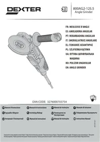
USER MANUAL 800AG2-125.5001 EAN CODE : 3276007726442 Angle Grinder DEXTER
natural_image
Technical line drawing of a mechanical power tool with no visible text or symbols
FR Meuleuse d'angle
ES Amoladora angular
PT Rebarbadora angular
natural_image
Technical line drawing of a mechanical device with no visible text or symbols
natural_image
Technical line drawing of a mechanical device with no visible text or symbols
natural_image
Technical line drawing of a mechanical device with no visible text or symbols
natural_image
Technical line drawing of a mechanical device with no visible text or symbols
natural_image
Technical line drawing of a mechanical device with no visible text or symbols
BEZPIECZEŃSTWO W MIEJSCU PRACY
natural_image
Technical line drawing of a mechanical device with no visible text or symbols
natural_image
Technical line drawing of a mechanical device with no visible text or symbols
natural_image
Technical line drawing of a mechanical device with no visible text or symbols
Please read the operating instruction carefully and observe the notes given. Use these operating instructions to familiarise yourself with the product, the proper use and the safety instructions. Keep these operating instructions in a safe place for future uses.
SYMBOLS

Read instruction manual carefully

This danger notice warns of damage to the appliance or others properties, or may cause physical injuries.

Wear safety glasses

Wear ear protection

Wear safety shoes

Wear protective gloves

Wear a dust mask

Using damaged cutting or roughing discs is dangerous and may cause serious injury.

Not approved for wet grinding

Not approved for side grinding

Intended for metal grinding

The product complies with the applicable European directives and an evaluation method of conformity for these directives was done.
SYMBOLS

Eurasian conformity work.

Weee symbol for recycling operation.

Conformity marking that product comply with applicable Ukraine technical regulations.

Always operate with two hands

Do not use the guard for cut-off operations

Disconnect mains plug from electrical outlet

Class II machine - Double insulation - You don't need any earthed plug
CONTENTS
- Intended use of Dexter angle grinder
- Safety instructions
- Description
- Technical data
- Operation
- Maintenance
- Trouble shooting
- Recycling
- Warranty
- Exploded view with part list
- EC Declaration of conformity
1. INTENDED USE OF DEXTER ANGLE GRINDER
Thank you for purchasing this product. Please read through these operating instructions and keep them for future reference.
The angle grinder is intended for grinding, cutting and brushing metal or tiles without the use of water.
After unwrapping the packing, make sure that the product is complete with its accessories (if any). If the product is damaged or has any defect, please do not use it and bring back it to your dealer.
If you give this tool to another people, please give him also this instruction manual.
Please note that our equipment has not been designed for use in commercial, trade or industrial applications. Our warranty will be voided if the machine is used in commercial, trade or industrial businesses or for equivalent purposes.
For safety reasons, children and young people under the age of 16, as well as people not familiar with these operating instructions, may not use this product. Persons with reduced physical or mental abilities may use the product only if they are supervised or instructed by a responsible person.
2. SAFETY INSTRUCTIONS

WARNING: Read all safety warnings, instructions, illustrations and specifications provided with this power tool. Failure to follow all instructions listed below may result in electric shock, fire and/or serious injury.
SAVE ALL WARNINGS AND INSTRUCTIONS FOR FUTURE REFERENCE.
The term "power tool" in the warnings refers to your main-operated (corded) power tool or battery-operated (cordless) power tool..
WORK AREA SAFETY
A. Keep work area clean and well lit. Cluttered or dark areas invite accidents.
B. Do not operate power tools in explosive atmospheres, such as in the presence of flammable liquids, gases or dust. Power tools create sparks which may ignite the dust or fumes.
C. Keep children and bystanders away while operating a power tool. Distractions can cause you to lose control.
ELECTRICAL SAFETY
A. Power tool plugs must match the outlet. Never modify the plug in any way. Do not use any adapter plugs with earthed (grounded) power tools. Unmodified plugs and matching outlets will reduce risk of electric shock.
B. Avoid body contact with earthed or grounded surfaces, such as pipes, radiators, ranges and refrigerators. There is an increased risk of electric shock if your body is earthed or grounded.
C. Do not expose power tools to rain or wet conditions. Water entering a power tool will increase the risk of electric shock.
D. Do not abuse the cord. Never use the cord for carrying, pulling or unplugging the power tool. Keep cord away from heat, oil, sharp edges or moving parts. Damaged or entangled cords increase the risk of electric shock.
E. When operating a power tool outdoors, use an extension cord suitable for outdoor use. Use of a cord suitable for outdoor use reduces the risk of electric shock.
F. If operating a power tool in a damp location is unavoidable, use a residual current device (RCD) protected supply. Use of an RCD reduces the risk of electric shock.
PERSONAL SAFETY
A. Stay alert, watch what you are doing and use common sense when operating a power tool. Do not use a power tool while you are tired or under the influence of drugs, alcohol or medication. A moment of inattention while operating power tools may result in serious personal injury.
B. Use personal protective equipment. Always wear eye protection. Protective equipment such as dust mask, non-skid safety shoes, hard hat, or hearing protection used for appropriate conditions will reduce personal injuries.
C. Prevent unintentional starting. Ensure the switch is in the off-position before connecting to power source, picking up or carrying the tool. Carrying power tools with your finger on the switch or energising power tools that have the switch on invites accidents.
D. Remove any adjusting key or wrench before turning the power tool on. A wrench or a key left attached to a rotating part of the power tool may result in personal injury.
E. Do not overreach. Keep proper footing and balance at all times. This enables better control of the power tool in unexpected situations.
F. Dress properly. Do not wear loose clothing or jewellery. Keep your hair, clothing and gloves away from moving parts. Loose clothes, jewellery or long hair can be caught in moving parts.
G. If devices are provided for the connection of dust extraction and collection facilities, ensure these are connected and properly used. Use of dust collection can reduce dust-related hazards.
H. Do not let familiarity gained from frequent use of tools allow you to become complacent and ignore tool safety principles. A careless action can cause severe injury within a fraction of a second.
A. Do not force the power tool. Use the correct power tool for your application. The correct power tool will do the job better and safer at the rate for which it was designed.
B. Do not use the power tool if the switch does not turn it on and off. Any power tool that cannot be controlled with the switch is dangerous and must be repaired.
C. Disconnect the plug from the power source of the power tool before making any adjustments, changing accessories, or storing power tools. Such preventive safety measures reduce the risk of starting the power tool accidentally.
D. Store idle power tools out of the reach of children and do not allow persons unfamiliar with the power tool or these instructions to operate the power tool. Power tools are dangerous in the hands of untrained users.
E. Maintain power tools and accessories. Check for misalignment or binding of moving parts, breakage of parts and any other condition that may affect the power tools operation. If damaged, have the power tool repaired before use. Many accidents are caused by poorly maintained power tools.
F. Keep cutting tools sharp and clean. Properly maintained cutting tools with sharp cutting edges are less likely to bind and are easier to control.
G. Use the power tool, accessories and tool bits etc. in accordance with these instructions, taking into account the working conditions and the work to be performed. Use of the power tool for operations different from those intended could result in a hazardous situation.
H. Keep handles and grasping surfaces dry, clean and free from oil and grease. Slippery handles and grasping surfaces do not allow for safe handling and control of the tool in unexpected situations.
SERVICE
A. Have your power tool serviced by a qualified repair person using only identical replacement parts. This will ensure that the safety of the power tool is maintained.
SAFETY INSTRUCTIONS FOR GRINDER, CUT-OFF TOOL, SANDER AND WIRE BRUSHING OPERATIONS
A) THIS POWER TOOL IS INTENDED TO FUNCTION AS A GRINDER, CUT-OFF TOOL, SANDER AND WIRE BRUSHING OPERATION. READ ALL SAFETY WARNINGS, INSTRUCTIONS, ILLUSTRATIONS AND SPECIFICATIONS PROVIDED WITH THIS POWER TOOL. FAILURE TO FOLLOW ALL INSTRUCTIONS LISTED BELOW MAY RESULT IN ELECTRIC SHOCK, FIRE AND/OR SERIOUS INJURY.
B) OPERATIONS SUCH AS POLISHING OR HOLE CUTTING ARE NOT TO BE PERFORMED WITH THIS POWER TOOL. OPERATIONS FOR WHICH THE POWER TOOL WAS NOT DESIGNED MAY CREATE A HAZARD AND CAUSE PERSONAL INJURY.
C) DO NOT CONVERT THIS POWER TOOL TO OPERATE IN A WAY WHICH IS NOT SPECIFICALLY DESIGNED AND SPECIFIED BY THE TOOL MANUFACTURER. SUCH A CONVERSION MAY RESULT IN A LOSS OF CONTROL AND CAUSE SERIOUS PERSONAL INJURY.
D) DO NOT USE ACCESSORIES WHICH ARE NOT SPECIFICALLY DESIGNED AND SPECIFIED BY THE TOOL MANUFACTURER. JUST BECAUSE THE ACCESSORY CAN BE ATTACHED TO YOUR POWER TOOL, IT DOES NOT ASSURE SAFE OPERATION.
E) THE RATED SPEED OF THE ACCESSORY MUST BE AT LEAST EQUAL TO THE MAXIMUM SPEED MARKED ON THE POWER TOOL. ACCESSORIES RUNNING FASTER THAN THEIR RATED SPEED CAN BREAK AND FLY APART.
F) THE OUTSIDE DIAMETER AND THE THICKNESS OF YOUR ACCESSORY MUST BE WITHIN THE CAPACITY RATING OF YOUR POWER TOOL. INCORRECTLY SIZED ACCESSORIES CANNOT BE ADEQUATELY GUARDED OR CONTROLLED.
G) THE DIMENSIONS OF THE ACCESSORY MOUNTING MUST FIT THE DIMENSIONS OF THE MOUNTING HARDWARE OF THE POWER TOOL. ACCESSORIES THAT DO NOT MATCH THE MOUNTING HARDWARE OF THE POWER TOOL WILL RUN OUT OF BALANCE, VIBRATE EXCESSIVELY AND MAY CAUSE LOSS OF CONTROL.
H) DO NOT USE A DAMAGED ACCESSORY. BEFORE EACH USE INSPECT THE ACCESSORY SUCH AS ABRASIVE WHEELS FOR CHIPS AND CRACKS, BACKING PAD FOR CRACKS, TEAR OR EXCESS WEAR, WIRE BRUSH FOR LOOSE OR CRACKED WIRES. IF POWER TOOL OR ACCESSORY IS DROPPED, INSPECT FOR DAMAGE OR INSTALL AN UNDAMAGED ACCESSORY. AFTER INSPECTING AND INSTALLING AN ACCESSORY, POSITION YOURSELF AND BYSTANDERS AWAY FROM THE PLANE OF THE ROTATING ACCESSORY AND RUN THE POWER TOOL AT MAXIMUM NO-LOAD SPEED FOR ONE MINUTE. DAMAGED ACCESSORIES WILL NORMALLY BREAK APART DURING THIS TEST TIME.
I) WEAR PERSONAL PROTECTIVE EQUIPMENT. DEPENDING ON APPLICATION, USE FACE SHIELD, SAFETY GOGGLES OR SAFETY GLASSES. AS APPROPRIATE, WEAR DUST MASK, HEARING PROTECTORS, GLOVES AND WORKSHOP APRON CAPABLE OF STOPPING SMALL ABRASIVE OR WORKPIECE FRAGMENTS. THE EYE PROTECTION MUST BE CAPABLE OF STOPPING FLYING DEBRIS GENERATED BY VARIOUS APPLICATIONS. THE DUST MASK OR RESPIRATOR MUST BE CAPABLE OF FILTRATING PARTICLES GENERATED BY THE PARTICULAR APPLICATION. PROLONGED EXPOSURE TO HIGH INTENSITY NOISE MAY CAUSE HEARING LOSS.
J) KEEP BYSTANDERS A SAFE DISTANCE AWAY FROM WORK AREA. ANYONE ENTERING THE WORK AREA MUST WEAR PERSONAL PROTECTIVE EQUIPMENT. FRAGMENTS OF WORKPIECE OR OF A BROKEN ACCESSORY MAY FLY AWAY AND CAUSE INJURY BEYOND IMMEDIATE AREA OF OPERATION.
K) HOLD THE POWER TOOL BY INSULATED GRIPPING SURFACES ONLY, WHEN PERFORMING AN OPERATION WHERE THE CUTTING ACCESSORY MAY CONTACT HIDDEN WIRING OR ITS OWN CORD. CUTTING ACCESSORY CONTACTING A «LIVE» WIRE MAY MAKE EXPOSED METAL PARTS OF THE POWER TOOL «LIVE» AND COULD GIVE THE OPERATOR AN ELECTRIC SHOCK.
L) POSITION THE CORD CLEAR OF THE SPINNING ACCESSORY. IF YOU LOSE CONTROL, THE CORD MAY BE CUT OR SNAGGED AND YOUR HAND OR ARM MAY BE PULLED INTO THE SPINNING ACCESSORY.
M) NEVER LAY THE POWER TOOL DOWN UNTIL THE ACCESSORY HAS COME TO A COMPLETE STOP. THE SPINNING ACCESSORY MAY GRAB THE SURFACE AND PULL THE POWER TOOL OUT OF YOUR CONTROL.
N) DO NOT RUN THE POWER TOOL WHILE CARRYING IT AT YOUR SIDE. ACCIDENTAL CONTACT WITH THE SPINNING ACCESSORY COULD SNAG YOUR CLOTHING, PULLING THE ACCESSORY INTO YOUR BODY.
O) REGULARLY CLEAN THE POWER TOOL'S AIR VENTS. THE MOTOR'S FAN WILL DRAW THE DUST INSIDE THE HOUSING AND EXCESSIVE ACCUMULATION OF POWDERED METAL MAY CAUSE ELECTRICAL HAZARDS.
P) DO NOT OPERATE THE POWER TOOL NEAR FLAMMABLE MATERIALS. SPARKS COULD IGNITE THESE MATERIALS.
Q) DO NOT USE ACCESSORIES THAT REQUIRE LIQUID COOLANTS. USING WATER OR OTHER LIQUID COOLANTS MAY RESULT IN ELECTROCUTION OR SHOCK.
2. SAFETY INSTRUCTIONS
FURTHER SAFETY INSTRUCTIONS FOR ALL OPERATIONS
Kickback is a sudden reaction to a pinched or snagged rotating wheel, backing pad, brush or any other accessory. Pinching or snagging causes rapid stalling of the rotating accessory which in turn causes the uncontrolled power tool to be forced in the direction opposite of the accessory's rotation at the point of the binding.
For example, if an abrasive wheel is snagged or pinched by the workpiece, the edge of the wheel that is entering into the pinch point can dig into the surface of the material causing the wheel to climb out or kick out.
The wheel may either jump toward or away from the operator, depending on direction of the wheel's movement at the point of pinching. Abrasive wheels may also break under these conditions. Kickback is the result of power tool misuse and/or incorrect operating procedures or conditions and can be avoided by taking proper precautions as given below.
A. Maintain a firm grip on the power tool and position your body and arm to allow you to resist kickback forces. Always use auxiliary handle, if provided, for maximum control over kickback or torque reaction during start-up. The operator can control torque reactions or kickback forces, if proper precautions are taken.
B. Never place your hand near the rotating accessory. Accessory may kickback over your hand.
C. Do not position your body in the area where power tool will move if kickback occurs. Kickback will propel the tool in direction opposite to the wheel's movement at the point of snagging.
D. Use special care when working corners, sharp edges etc. Avoid bouncing and snagging the accessory. Corners, sharp edges or bouncing have a tendency to snag the rotating accessory and cause loss of control or kickback.
E. Do not attach a saw chain woodcarving blade, segmented diamond wheel with a peripheral gap greater than 10 mm or toothed saw blade. Such blades create frequent kickback and loss of control.
Safety Warnings Specific for Grinding and Abrasive Cutting Off Operations:
A. Use only wheel types that are recommended for your power tool and the specific guard designed for the selected wheel. Wheels for which the power tool was not designed cannot be adequately guarded and are unsafe.
B. The grinding surface of centre depressed wheels must be mounted below the plane of the guard lip. An improperly mounted wheel that projects through the plane of the guard lip cannot be adequately protected.
C. The guard must be securely attached to the power tool and positioned for maximum safety, so the least amount of wheel is exposed towards the operator. The guard helps to protect the operator from broken wheel fragments, accidental contact with wheel and sparks that could ignite clothing.
D. Wheels must be used only for recommended applications. For example: do not grind with the side of cut-off wheel. Abrasive cut-off wheels are intended for peripheral grinding, side forces applied to these wheels may cause them to shatter.
E. Always use undamaged wheel flanges that are of correct size and shape for your selected wheel. Proper wheel flanges support the wheel thus reducing the possibility of wheel breakage. Flanges for cut-off wheels may be different from grinding wheel flanges.
F. Do not use worn down wheels from larger power tools. Wheel intended for larger power tool is not suitable for the higher speed of a smaller tool and may burst.
G. When using dual purpose wheels always use the correct guard for the application being performed. Failure to use the correct guard may not provide the desired level of guarding, which could lead to serious injury.
Additional Safety Warnings Specific for Cutting-Off Operations:
A. Do not "jam" the cut-off wheel or apply excessive pressure. Do not attempt to make an excessive depth of cut. Overstressing the wheel increases the loading and susceptibility to twisting or binding of the wheel in the cut and the possibility of kickback or wheel breakage.
B. Do not position your body in line with and behind the rotating wheel. When the wheel, at the point of operation, is moving away from your body, the possible kickback may propel the spinning wheel and the power tool directly at you.
C. When wheel is binding or when interrupting a cut for any reason, switch off the power tool and hold the power tool motionless until the wheel comes to a complete stop. Never attempt to remove the cut-off wheel from the cut while the wheel is in motion otherwise kickback may occur. Investigate and take corrective action to eliminate the cause of wheel binding.
D. Do not restart the cutting operation in the workpiece. Let the wheel reach full speed and carefully re-enter the cut. The wheel may bind, walk up or kickback if the power tool is restarted in the workpiece.
E. Support panels or any oversized workpiece to minimize the risk of wheel pinching and kickback. Large workpieces tend to sag under their own weight. Supports must be placed under the workpiece near the line of cut and near the edge of the workpiece on both sides of the wheel.
F. Use extra caution when making a "pocket cut" into existing walls or other blind areas. The protruding wheel may cut gas or water pipes, electrical wiring or objects that can cause kickback.
G. Do not attempt to do curved cutting. Overstressing the wheel increases the loading and susceptibility to twisting or binding of the wheel in the cut and the possibility of kickback or wheel breakage, which can lead to serious injury.
Additional safety instructions for sanding operations:
a) Use proper sized sanding disc paper. Follow manufacturers recommendations, when selecting sanding paper. Larger sanding paper extending too far beyond the sanding pad presents a laceration hazard and may cause snagging, tearing of the disc or kickback.
Additional safety instructions for wire brushing operations:
a) Be aware that wire bristles are thrown by the brush even during ordinary operation. Do not overstress the wires by applying excessive load to the brush. The wire bristles can easily penetrate light clothing and/or skin.
b) If the use of a guard is specified for wire brushing, do not allow any interference of the wire wheel or brush with the guard. Wire wheel or brush may expand in diameter due to work load and centrifugal forces.
3. DESCRIPTION
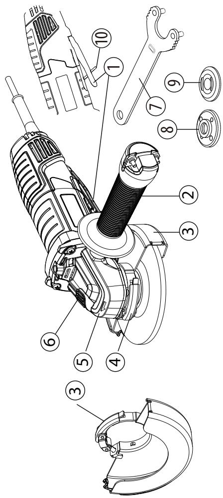
1 Paddle
2 Side handle
3 Protective cover
(2 in 1 guard 125mm)
4 Guard locking lever
5 Gear box
6 Lock button
7 Spanner
8 External flange with thread
9 Internal flange
10 Safety interlock
4. TECHNICAL DATA
| Model | 800AG2-125.5001 |
| Rated voltage: | 220-240 V~ |
| Rated Power | 800W |
| Rated no-load speed: | 12000min^-1 |
| Disc diameter | 125mm |
| Disc bore: | 22.2mm |
| Spindle thread: | M14 |
| Sound pressure level: | L_pA : 93,0 dB(A) |
| Uncertainty | K_pA : 3,0 dB(A) |
| Sound power level | L_wA : 101,0 dB(A) |
| Uncertainty | K_wA : 3,0 dB(A) |
| Vibration level | <2,5 m/s^2 |
| Uncertainty | K = 1,5 m/s^2 |
| Machine weight | 2,2 kg |
| Diameter of grinding wheels | 125mm |
| Permitted thickness of grinding wheels | 6.5mm |
| Maximum diameter of wheel-type wire brushes | 125mm |
| Maximum thickness of wheel-type wire brushes | 11.5mm |
| Permitted construction of cutting-off wheels | Diamond and bonded reinforced |
| Permitted wheel diameter | 125mm |
| Permitted wheel thickness | 3mm |
| Maximum peripheral gap between segments for diamond cutting-off wheels | 10mm |
NOTE: The declared vibration total value(s) and the declared noise emission value(s) have been measured in accordance with a standard test method and may be used for comparing one tool with another;
The declared vibration total value(s) and the declared noise emission value(s) may also be used in a preliminary assessment of exposure.
WARNING! The vibration and noise emissions during actual use of the power tool can differ from the declared values depending on the ways in which the tool is used especially what kind of workpiece is processed;
The emissions need to identify safety measures to protect the operator that are based on an estimation of exposure in the actual conditions of use (taking account of all parts of the operating cycle such as the times when the tool is switched off and when it is running idle in addition to the trigger time).
WARNING! Grinding thin sheets of metal or other easily vibrating structures with a large surface can result in a total noise emission much higher (up to 15 dB) than the declared noise emission values. Such workpieces should as far as possible be prevented from emitting sound by suitable measures such as the application of heavy flexible damping mats. The increased noise emission is also to be considered for both the risk assessment of noise exposure and selecting adequate hearing protection.
5. OPERATION
SWITCH TRIGGER
To turn the grinder ON, push forward the orange button below the handle and press the switch trigger.
To turn it OFF, just release the switch trigger
GENERAL OPERATION
- If you have just installed an accessory or are beginning a period of work, test the disc by letting it spin for one minute before applying it to the workpiece. WARNING! Never use an accessory that has been dropped. Out-of-balance or damaged accessories can damage workpiece, damage the tool, and cause stress that may cause accessory failure.
- Use a clamp, vise or other practical means to hold your work, freeing both hands to control the tool.
- WARNING! Hold tool securely with both hands.
- Allow accessory to come to full speed before beginning work.
- Control pressure and surface contact between accessory and workpiece. WARNING! Never bang accessory onto work. Too much pressure causes accessory failure or slows speed.
- When finished, turn off the tool and make sure it comes to a complete stop before laying it down.
USING QUICK GUARD FOR GRINDING
For grinding operation, always use the specific guard dedicated to grinding operation.
The guard type must match the disc type to provide maximum protection for the operator if the disc should break.
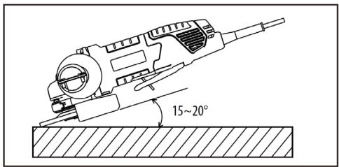
When side grinding and peripheral grinding applications, hold tools at a 15^ to 20^ angle, using constant pressure for a uniform finish.
Too great an angle causes concentrated pressure on small areas which may gouge or burn the work surface.
WARNING! When using a Type A (cut-off) wheel guard for facial grinding, the wheel guard may interfere with the workpiece causing poor control
WARNING! When using a Type A (cut-off), Type B (grinding) or Type C (combination) wheel guard for cutting-off and facial operations in concrete or masonry, there is an increased risk of exposure to dust and loss of control resulting in kickback
USING QUICK GUARD FOR CUTTING
For cutting operation, always use the specific guard dedicated to cut off operations
Quick guard for cutting is suited for small cut-off and shallow notching operations only.
WARNING: The guard type must match the disc type to provide maximum protection for the operator if the wheel should break. When using a quick guard for cutting, hold the tool as shown, using only the edge of the disc.
WARNING! Using the face of a quick guard for cutting will cause the disc to crack and break, resulting in serious personal injury
WARNING! When using a Type B (grinding) wheel guard for cutting-off operations with bonded abrasive wheels, there is an increased risk of exposure to emitted sparks and particles, as well as exposure to wheel fragments in the event of wheel burst.
WARNING! When using a Type A (cut-off), Type B (grinding) or Type C (combination) wheel guard for cutting-off and facial operations in concrete or masonry, there is an increased risk of exposure to dust and loss of control resulting in kickback
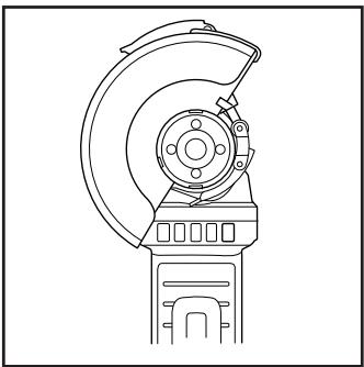
POSITIONING THE GUARD
The guard on the grinder should be correctly positioned depending on which side the handle is mounted. Never use the grinder without the guard correctly in place.
WARNING: Never place the guard so that it is in front of the grinder.
This could result in serious injury because sparks and loose particles thrown from the disc would be directed toward the operator. Always place the guard in the correct location.
To reposition the guard:
Unlock the guard clasp by pulling the clasp out, rotate the guard to its correct position, away from the grinder.
Lock the guard clasp by pushing the clasp in.
NOTE: Be sure the raised ridge on the guard is seated in the groove on the bearing cap. Never use the grinder without the guard in place and properly adjusted.

Before repositionning the guard please make sure that the powertool is unplugged from the power source.
Installing or moving protective cover
WARNING: Ensure the angle grinder is switch off and unplugged from the mains.
Depending on whether your operation is cutting or grinding, select the correct protective cover. Failure to use the right cover for operation could result in injury. When using a grinding or cutting-off wheel, the protective guard must be fitted on the tool so that the closed side of the cover always points toward the operator.
Install the guard: release the lock lever of the guard and insert it on the gear head, and turn/adjust in any desired position for maximum performance, then close the lock lever. Make sure that the fastening lever is properly locked after setting the guard.
To remove the protective cover, follow the installation procedure in reverse. The protective cover can be turned to a desired angle, but not more than 45^ on left side or right side.
natural_image
Technical line drawing of a mechanical device with no visible text or symbols
Please use grinding protective cover for grinding operation.
Grinding and Surface Processing
In order to grind surface, you should use a coarse abrasive disk with a sunken centre. You can use the abrasive disks with diameter of 125mm. The maximum thickness of disks is 6mm.
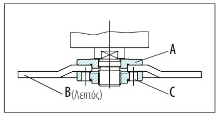
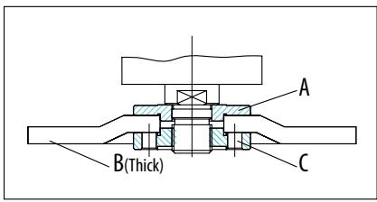
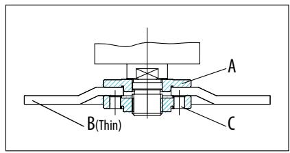
Mounting the Wheels /Disks
Place the back flange A over the spindle making sure that it fits tight.
Place the grinding or cutting disc B on the top of the back flange, ensuring the bore fits into the step of the flange.
Mount the external flange C over the spindle.
Press the spindle lock button to lock the spindle firmly, then tighten the external flange with the spanner in clockwise direction.
Allow the angle grinder to run in idle at least 1 minute with the grinding or cutting disc correctly assembled, a vibration disc should be immediately replaced.
For flange arrangements when using grinding wheels and cutting wheels, please refer to the assembly instruction manual.
OPERATING INSTRUCTIONS / DRAWINGS
Switch ON/OFF
Switch on: Push the lock off button forwards meanwhile clenching the paddle to turn on the machine. Then keep hold it in position for continuous operation.
Switch off: Loosen the switch trigger to turn off the machine.
WARNING: Do not cover exhaust vents when the tool is in use. This may cause damage to the motor and reduce the efficiency of the tool.
Abrasive operation
When equipped with abrasive wheel and guard, for the best work results hold the grinder at 15\~20° to the work piece.
CAUTION: Check operation of brush by running tool with no load, insuring that no one is in front of or in line with brush.

CAUTION: Do not use brush that is damaged, or which is out of balance. Use of damaged brush could increase potential for injury from contact with broken brush wires.
Unplug tool and place it upside down allowing easy access to spindle. Remove any accessories on spindle. Thread wire cup brush onto spindle.
NOTICE: Avoid applying too much pressure which causes over bending of wires when using brush. It may lead to premature breakage.
CAUTION: Check operation of wire wheel brush by running tool with no load, insuring that no one is in front of or in line with the wire wheel brush.

CAUTION: Do not use wire wheel brush that is damaged, or which is out of balance. Use of damaged wire wheel brush could increase potential for injury from contact with broken wires.

CAUTION: ALWAYS use guard with wire wheel brushes, assuring diameter of wheel fits inside guard. Wheel can shatter during use and guard helps to reduce chances of personal injury. When using wheel guard with a wheel-type wire brush with a thickness greater than the maximum thickness as technical data, the wires may catch on the guard leading to breaking of wires.
Unplug tool and place it upside down allowing easy access to spindle. Remove any accessories on spindle. Thread wire wheel brush onto spindle.
NOTICE: Avoid applying too much pressure which causes over bending of wires when using wire wheel brush. It may lead to premature breakage.
OVERLOAD
The motor of your right angle grinding machine may be damaged when overloaded. This results from excessive working pressure over a prolonged period. Therefore you should not try to accelerate your working speed by increasing pressure on your machine. The abrasive disks work more efficiently if only slight pressure is exerted on the grinding machine, thus avoiding a drop in the grinding speed.

WARNING! RISK OF INJURY! Always switch the appliance off and unplug before carrying out any work on the appliance.
Do not use any sharp objects for cleaning the appliance. Never allow any liquids to penetrate inside the appliance. Otherwise the appliance could be damaged.
Clean the appliance regularly, preferably immediately after completion of the work.
Clean the housing with a dry cloth—do NOT use petrol, solvents or cleaners which can attack the plastic.
A vacuum cleaner is required for thorough cleaning of the appliance.
Ventilation openings must never be obstructed.
Remove any sanding dust stuck to the appliance with a brush.
If the replacement of the supply cord is necessary, this has to be done by the manufacturer or his agent in order to avoid a safety hazard
CLEANING
Clean dust and debris from vents. Keep handles clean, dry and free of oil or grease. Use only mild soap and a damp cloth to clean, since certain cleaning agents and solvents are harmful to plastics and other insulated parts. Some of these include gasoline, turpentine, lacquer thinner, paint thinner, chlorinated cleaning solvents, ammonia and household deter-gents containing ammonia. Never use flammable or combustible solvents around tools.
REPAIRS
For repairs, return the tool to the nearest service center.
STORAGE & DISPOSAL
Switch the angle grinder off and unplug it.
Store the angle grinder and its accessories in a dark, dry, frost-free, well-ventilated place.
6. MAINTENANCE
Always store the angle grinder in a place that is inaccessible to children. The ideal storage temperature is between 10^ C and 30^ C.
We recommend using the original package for storage or covering the angle grinder with a suitable cloth or enclosure to protect it against dust.
TRANSPORTATION
Switch the angle grinder off.
Protect the angle grinder from any heavy impact or strong vibrations which may occur during transportation in vehicles.
Secure the angle grinder to prevent it from slipping or falling over.
7. TROUBLE SHOOTING
| Problems | Probable causes | Corrective action |
| Device doesn’t start | On/off switch may be defective. | Repair by customer care |
| Engine faulty |
| Grinding tools do not move although the engine is running | Grinding disc nut is loose | Tighten grinder dies nut |
| Workpiece, remaining workpieces or remaining grinding tools block drive | Remove blockages |
| Grinding disc does rotate smoothly,abnormal noises can be heard | Grinding disc nut is loose | Tighten grinding disc nut |
| Grinding disc is defective | Change grinding disc |
8. RECYCLING

The packaging consists of environmentally friendly material. It can be disposed of in the local recycling containers.

CAUTION! This product has been marked with a symbol relating to removing electric and electronic waste. This means that this product shall not be discarded with household waste but that it shall be returned to a collection system which conforms to the European WEEE Directive. Contact your local authorities or stocks for advice on recycling. It will then be recycled or dismantled in order to reduce the impact on the environment. Electric and electronic equipment can be hazardous for the environment and for human health since they contain hazardous substances.
ENVIRONMENTAL PROTECTION
Waste electrical products must not be disposed of with household waste. Please recycle where facilities exist. Check with your local authorities or retailer for recycling advice. It will then be recycled or dismantled in order to reduce the impact on the environment.
9. WARRANTY
PREFACE
Thank you for choosing this product. Upon designing and manufacturing our products, we place all of our efforts into ensuring an excellent quality that meets the needs of the users.
IMPORTANT! PLEASE READ THIS MANUAL BEFORE USING THIS PRODUCT, FOLLOW THE BASIC SAFETY WARNINGS WITHIN, AND KEEP IT CAREFULLY.
As soon as you open the packaging, we recommend that you check to ensure that all elements required for assembly of the product have been included.
If the product is damaged or has some defects, please do not use it, and bring it back to the nearest store.
This product is intended for outdoor use only, and must not be used inside a building under any circumstances.
This product can be placed inside a building only after having rested for two hours after the last use.
We thank you for your business and hope that you will be totally satisfied upon using our product.
We will be happy to receive all of your remarks on our online store web site.
Warranty
DEXTER products are designed based on the most rigorous quality standards for products intended for the general public.
The angle grinder is covered with a warranty of 5 years starting from the date of purchase. This warranty covers all manufacturing or material defects.
In the event of a breakdown, please refer first to the troubleshooting page (problems and solutions) in the brochure; if the problem persists, please check with the nearest store.
Your store shall spare no effort in resolving the issue.
Repairs and change of parts do not extend the duration of the initial warranty.
Breakdowns resulting from normal wear and tear or from improper use of the product are not covered by the warranty. This includes, among others, the switches, the safety circuit breaker and the motors, in case of wear.
Please note that there are specific warranty terms for certain countries.
In case of doubt, please check with your point of sale.
For claims relating to the warranty to be taken into account, the following is required:
The product must be used under normal usage circumstances, and for non-professional purposes. Therefore, excluded from this warranty are products used by landscaping companies, local authorities, as well as companies offering paid rentals or free loaning of equipment.
10. EXPLODED VIEW WITH PART LIST
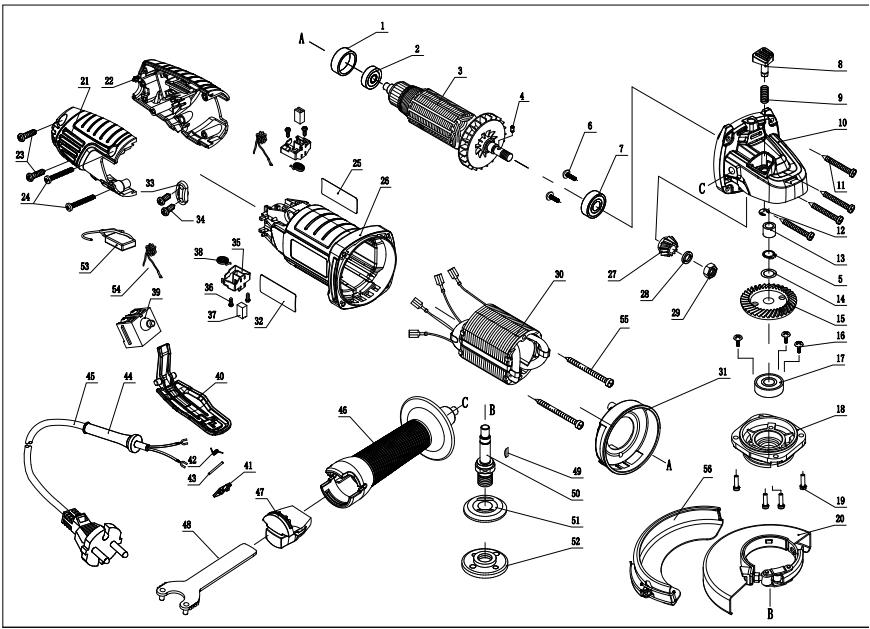
| N° | DESCRIPTION | QTY |
| 1 | Bearing set | 1 |
| 2 | Bearing | 1 |
| 3 | Armature | 1 |
| 4 | Roller 3X4.9 | 1 |
| 5 | Check ring φ10 | 1 |
| 6 | Special screw M5X8 | 2 |
| 7 | Bearing | 1 |
| 8 | Stop pin | 1 |
| 9 | Spring | 1 |
| 10 | Gear box | 1 |
| N° | DESCRIPTION | QTY |
| 11 | Tapping screw ST4X22 | 4 |
| 12 | Check ring | 1 |
| 13 | Column bearing | 1 |
| 14 | Spring washer | 1 |
| 15 | Gear | 1 |
| 16 | Special screw M4X7 | 3 |
| 17 | Bearing 6201 | 1 |
| 18 | Front cap | 1 |
| 19 | Screw and Spring washer M4X14 | 4 |
- EXPLODED VIEW WITH PART LIST
| N° | DESCRIPTION | QTY |
| 20 | Shield | 1 |
| 21 | Back cap (R) | 1 |
| 22 | Back cap (L) | 1 |
| 23 | Tapping screw ST4X16 | 2 |
| 24 | Tapping screw ST4X30 | 2 |
| 25 | Brand logo label | 1 |
| 26 | Housing | 1 |
| 27 | Pinion | 1 |
| 28 | Spring washer | 1 |
| 29 | Nut M8 | 1 |
| 30 | Stator | 1 |
| 31 | Fan guide | 1 |
| 32 | Rating label | 1 |
| 33 | Cord clamp | 1 |
| 34 | Tapping screw ST4X12 | 2 |
| 35 | Brush holder | 2 |
| 36 | Tapping screw ST2.9X8 | 4 |
| 37 | Brush | 2 |
| 38 | Brush spring | 2 |
| 39 | Switch | 1 |
| 40 | Switch drawbar | 1 |
| 41 | Switch button | 1 |
| 42 | Spring | 1 |
| 43 | Pin | 1 |
| 44 | Cord armor | 1 |
| 45 | Cord plug | 1 |
| N° | DESCRIPTION | QTY |
| 46 | Front handle | 1 |
| 47 | Spanner seat | 1 |
| 48 | Spanner | 1 |
| 49 | Woodruff key | 1 |
| 50 | Spindle | 1 |
| 51 | Flange | 1 |
| 52 | Flange nut | 1 |
| 53 | Capacitance | 1 |
| 54 | Inductance | 2 |
| 55 | Tapping screw ST4X65 | 2 |
| 56 | Shield | 1 |
88962015
Name and address of the manufacturer or his authorised representative|Nom et adresse du fabricant ou de son mandataire|Nombre y dirección del fabricante o de su representante autorizado|Nome e endereço do fabricante ou do seu representante autorizado|
ADEO Services, 135 Rue Sadi Carnot - CS 00001 59790 RONCHIN - France
This declaration of conformity is issued under the sole responsibility of the manufacturer|La présente déclaration de conformité est établie sous la seule responsabilité du fabricant|La presente declaración de conformidad se expide bajo la exclusiva responsabilidad del fabricante|Esta declaração de conformidade é emitida sob a exclusiva responsabilidade do fabricante.
Object of the declaration|Objet de la déclaration|Objeto de la declaración|Objeto da declaração|
88962015 - EAN Code: 3276007726442
Industrial Type Design Reference: 800AG2-125.5001
DEXTER
SN SSSSSS XX DDMMYY nn PPPPPP (SN: Serial No., SSSSSS : Supplier code, XX : Factory ID, DDMMYY: Production date, nn: number of version of product, PPPPPP : Incremental number)
References to the relevant harmonised standards used or references to the specifications in relation to which conformity is declared|Références des normes harmonisées pertinentes appliquées ou des spécifications par rapport auxquelles la conformité est déclarée|Referencias a las normas armonizadas pertinentes utilizadas, o referencias a las especificaciones respecto a las cuales se declara la conformidad|Referências às normas harmonizadas pertinentes utilizadas ou referências às especificações para as quais a conformidade é declarada|
EN 62841-1:2015 + A11:2022
EN IEC 62841-2-3: 2021+A11:2021
EN 61000-3-3:2013+ A1:2019+A2:2021
EN IEC 55014-1:2021
EN IEC 55014-2:2021
EN IEC 61000-3-2: 2019+A1:2021
Directive (EU) 2015/863
EN IEC 63000:2018
When applicable, the name and number of notified body number|Le cas échéant, le nom et le numérp de l'organisme notifié|Cuando corresponda * el nombre y número de laboratorio notificado que haya emitido la certificaci ón y la referencia al documento|Quando aplicável * o nome e número do laboratório notificado que emitiu a certificação e a referência ao documento|
Select the responsible and type code
Select the responsible and type code
2024/7/4
Signature
Modello di prodotto/prodotto|Model produktu/produkt|Μοντέλο προϊόντος/Προϊόν:|Modelul de produs/produsul:|
88962015
La presente dichiarazione di conformità è rilasciata sotto la responsabilità esclusiva del fabbricante|Niniejsza deklaracja zgodności wydana zostaje na wyłączną odpowiedzialność producenta.|Επινυμία και διεύθυνση του κατασκευαστή ή του εξουσιοδοτημένου αντιπροσώπου του|Denumirea și adresa producătorului sau a reprezentantului său autorizat:|
ADEO Services, 135 Rue Sadi Carnot - CS 00001 59790 RONCHIN - France
La presente dichiarazione di conformità è rilasciata sotto la responsabilità esclusiva del fabbricante|Niniejsza deklaracja zgodności wydana zostaje na wyłączną odpowiedzialność producenta.|H παρούσα δήλωση συμμόρφωσης εκδίδεται με αποκλειστική ευθύνη του κατασκευαστή|Declarația de conformitate este emisă pe răspunderea exclusivă a producătorului|
88962015 - EAN Code: 3276007726442
Industrial Type Design Reference: 800AG2-125.5001
DEXTER
SN SSSSSS XX DDMMYY nn PPPPPP (SN: Serial No., SSSSSS : Supplier code, XX : Factory ID, DDMMYY: Production date, nn: number of version of product, PPPPPP : Incremental number)
L'oggetto della dichiarazione di cui sopra è conforme alla pertinente normativa di armonizzazione dell'Unione|Wymieniony powyżej przedmiot niniejszej deklaracji jest zgodny z odnośnymi wymaganiami unijnego prawodawstwa harmonizacyjnego|O στόχος της δήλωσης που περιγράφ εται παραπάνω είναι σύμφωνος με τη σχετική ενωσιακή νομοθεσία εναρ μόνιας;|Obiectul declarației descris mai sus este în conformitate cu legislația comunitară relevantă de armonizare a Uniunii|
Riferimenti alle pertinenti norme armonizzate utilizzate o alle specifiche in relazione alle quali è dichiarata la conformità|Odwo lania do odnośnych norm zharmonizowanych, które zastosowano, lub do specyfikacji, w odniesieniu do których deklarowana jest zgodność:|Mveía tων σχετικών εναρμονισμέν ων προτύπων που χρησιμοποιούνται ή μνεία των προδιαγραφών ν σε σχέση με τις οποίες δηλώνεται η συμμόρφωση:|Referintele standardelor armonizate relevante folosite sau referintele specificațiilor în legătură cu care se declară conformitatea:|
Dove applicabile * il nome e il numero del laboratorio notificato che ha rilasciato la certificazione e il riferimento al documento|W stosownych przypadkach * notyfikowana nazwa i numer laboratorium, które wydało certyfikat oraz odniesienie do dokumentu|Otpou ixχύει * to γνωστοποιημέ vo όνομα και τον αριθμό του εργαστηρίου που εξέδωσε την πιστοποίηση και την αναφορά στο έγγραφο|Unde este cazul * numele și numårul de laborator notificat care a eliberat certificarea și trimiterea la document|
2006_42_EC_MACHINE
EN IEC 62841-2-3: 2021+A11:2021
2014_30_EU_EMC
compatibilità elettromagnetica|kompatybilności
elektromagnetycznej |ηλεκτρομαγνητική συμβατότητα
|compatibilitatea electromagneticčá|
EN 61000-3-3:2013+ A1:2019+A2:2021
EN IEC 55014-1:2021
EN IEC 55014-2:2021
EN IEC 61000-3-2: 2019+A1:2021
2011_65_EU_RoHS
Restrizione di sostanze pericolose nelle apparecchiature elettriche|Ograniczenie niebezpiecznych substancji w sprzęcie elektrycznym|Периориσμός επικίνδυνων ουσιών σε ηλεκτρικό ξξοπ λισμο|Restrictionarea substanțelor periculoase în echipamentele electrice|
Directive (EU) 2015/863
EN IEC 63000:2018
Compilato, firmato in vece e per conto di|Opracowano, podpisano w imieniu|Συντάχθηκε, υπογραφή για και εξ ονόματος|Compilat, semnat de și în numele|
Select the responsible and type code
Select the responsible and type code
2024/7/4
Signature
natural_image
Illustration of a globe with multiple flags flying around it, no text or symbols present.


PAP
FR. *Garantie de 5 ans sur la machine / ES. *Máquina garantía 5 años / PT. *Máquina 5 anos de garantía / IT. *Macchina 5 anni di garanzia / EL. *Mħανὴl 5 χρόνια εγγύηση / PL. *Maszyna 5 lat gwarancji / UA. *Taranția na машину 5 років / RO. *Mașină 5 ani garanție / EN. *Machine 5-year guarantee
Serial number / Numéro de série / Número de serie / Número de série / Numero di serie / Σειριακός αριδμός / Numer seryjny / Серійний номер / Număr serie


Made in CHINA 2024
ADEO Services - 135 Rue Sadi Carnot - CS 00001
59790 RONCHIN - France
Imported by Adeo South Africa (PTY) LTD T/A Leroy Merlin
Leroy Merlin Greenstone Store
Corner Blackrock Street and Stoneridge Drive, Greenstone Park Ext 2, Edenvale, 1610 Johannesburg, Gauteng, South Africa