
ExoActive EXO 18-Basic - Exoskeleton FESTOOL - Free user manual and instructions
Find the device manual for free ExoActive EXO 18-Basic FESTOOL in PDF.
| Product type | Exoskeleton |
| Brand | FESTOOL |
| Model | ExoActive EXO 18-Basic |
| Dimensions (transport) | 835 mm x 365 mm x 775 mm |
| Weight (without battery) | 7 kg |
| Power supply | Festool BP 18 Li battery ≥ 3.1 Ah, 18 V --- |
| Rated current | 4 A |
| Bluetooth frequency range | 2,402 MHz - 2,480 MHz, EIRP < 10 dBm |
| Operating temperature | 0 °C to 40 °C |
| User height | 160 cm - 200 cm |
| Assistance levels | 5 levels (0 to 5) |
| Preset profiles | 3 profiles: ceiling, wall, default |
| Sound pressure level | < 70 dB(A) |
| Vibrations (whole body) | < 0.5 m/s² |
| Vibrations (total) | < 2.5 m/s² |
| Maintenance and cleaning | Vacuum cleaning; textile parts washable at 30 °C in a washing bag, delicate cycle, do not wring or machine dry |
| Safety | Prohibited for wearers of active medical implants, do not use in rain, risk of finger crushing |
| Spare parts and repairability | Valve unit to be replaced every 5 years or 5000 h; use original Festool parts; repairs by authorized workshop |
| General information | Bluetooth® for connection to Festool Work app; data recording chip |
Frequently Asked Questions - ExoActive EXO 18-Basic FESTOOL
User questions about ExoActive EXO 18-Basic FESTOOL
0 question about this device. Answer the ones you know or ask your own.
Ask a new question about this device
Download the instructions for your Exoskeleton in PDF format for free! Find your manual ExoActive EXO 18-Basic - FESTOOL and take your electronic device back in hand. On this page are published all the documents necessary for the use of your device. ExoActive EXO 18-Basic by FESTOOL.
USER MANUAL ExoActive EXO 18-Basic FESTOOL
We as the manufacturer declare under our sole responsibility that the product(s) fulfill(s) all the relevant provisions of the following UK Regulations and are manufactured in accordance with the following designated standards:
S.I. 2008/1597 Supply of Machinery [Safety] Regulations 2008
S.I. 2017/1206 Radio Equipment Regulations 2017
S.I. 2012/3032 Restriction of the Use of Certain Hazardous Substances in Electrical and Electronic Equipment Regulations 2012
BS EN ISO 13482:2014
BS EN IEC 61000-6-2:2019
EN 300 328 V2.2.2
EN 301 489-1 V2.2.3
EN 301 489-17 V3.2.4
BS EN 62233:2008
BS EN 62479:2010
BS EN IEC 62368-1:2020 + A11:2020
BS EN IEC 63000:2018
The conformity assessment procedure as referenced in Article 17 and detailed in Annex III of the Radio Equipment Regulation S.I. 2017/1206 has been followed with the involvement of Notified Body:
NB name:TÜV AUSTRIA GmbH
NB number: 0408

Signed on behalf of and in name of
Festool GmbH
Wertstr. 20, 73240 Wendlingen, GERMANY
Place and date of declaration: Wendlingen, 2024-01-25
Markus Stark
Head of Research & Development Products
Tim Weber
Head of Product Compliance
| Exoskelett | Seriennummer * |
| Exoskeleton | Serial number * |
| Exosquelette | N° de série * |
| (T-Nr.) |
Exo 18
10334821, 10779819, 10802634
de EU-Konformitätserklarung. Wir erklären in al-leiniger Verantwortung, dass这点es Produkt mit allen relevanten Anforderungen folgender EU-Richtlinien übereinstimmt, und folgende Normen oder normative Dokumente zugrunde gelegt wurden:
en EU Declaration of Conformity. We declare under sole responsibility that this product complies with all the relevant requirements in the following EU Directives, and following standards or normative documents were applied:
fr Déclaration de conformité de l'UE. Nous déclarons, sous notre seule responsabilité, que ce produit satisfait à toutes les exigences pertinentes des directives UE suivantes et repose sur les normes ou documents normatifs suivants :
es Declaracion UE de conformidad. Declaramos bajo esta responsabilidad que este producto cumple todos los requisitos relevantes de las siguientes directivas de la UE y que se han tornado como base lassiguerentes normas o documents normativos:
it Dichiarazione di conformità UE. Dichiariamo molto nella sua responsabilità che il presente prodotto sa conforms a tutti i requisiti di rilevanza definiti nelle seguenti Direttive UE e che siano stati applicati le seguenti norme o i seguenti documenti normativi:
nl EU-conformiteitsverklaring. Wij verklaren en stellen ons ervoor verantwoordelijk dat dit product volledig voldoet aan alle volgende EU-richtlijnen en volgende normen of normatieve documenten daaraan ten grondslag gelegd werden:
SV EU-forsakran om overensstammelse. Vi Forklarar på eget ansvar att denna produkt uppfyller alla relevanta krav enligt följande EU-direktiv och baseras på följande normer eller normgivande Dokument:
fi EU-vaatimustenmukaisuusvakuutus. Vakuutamme yksinomaisella vastuulla, etta tämä tuote tayttäa seuraavien EU-direktiivien kaikki olennaiset vaatumukset ja se on seuraavien standardien tai standardiasiakirjojen mukainen:
da EU-overensstemmelseserklæring. Vi erklærer med eneansvar, at ditte produkt er i overensstemmelse med alle relevante krav i ffolgende EU-direktiver, og at ffolgende standarder eller normative dokumenter danner grundlag for det:
nb EU-samsvarserklæring. Vi erklærer under eneansvar at dette produktet oppfyller alle relevante krav i følgende EU-direktiver og at følgende standarder eller normative dokumenter er blitt lagt til grunn:
pt Declaração de conformidade UE. Sob)nossa inteira responsabilité,declarções que este produits está de acordo com todas as exigências relevantes das seguides direitivas UE, tendo sido tomadas por base
as següntes normas ou documentos normativos:
The conformity assessment procedure as referenced in Article 17 and detailed in Annex III of the
Radio Equipment Directive 2014/53/EU has been followed with the involvement of Notified Body:
NB name: TÜV AUSTRIA GmbH
NB number: 0408

Head of Research & Development Products
Tim Weber
Head of Product Compliance
Inhaltsverzeichnis
1 Symbols 21
2 Safety warnings. 21
3 Intended use 22
4 Technical data. 22
5 Device description. 23
6 Battery pack. 23
7 Commissioning. 23
8 Settings. 24
9 Working with the exoskeleton. 25
10 Status indicator. 29
11 Behaviour in the event of faults or accidents 29
12 Transport and storage 30
13 Service and maintenance. 30
14 Accessories. 31
15 Environment 31
16 General information. 32
1 Symbols

Warning of general danger

Warning of electric shock

Read the operating manual and safety warnings.

Prohibited for persons with active medical implants.

Risk of pinching fingers and hands!

Remove the battery pack.

Inserting the battery pack.

Tool contains a chip which stores data. See section 16.2

CE conformity marking

UKCA marking: Confirms the conformity of the product with UK regulations.

Do not dispose of it with domestic waste.

Tip or advice

Handling instruction
2 Safety warnings

WARNING! Read all safety warnings and instructions. Failure to follow the safety warnings and instructions may
result in electric shock, fire and/or serious injury.
Save all safety warnings and instructions for future reference.
Follow the operating manual for the charger and the battery pack.
2.1 Safety warnings
- Do not open incorrectly. Guards must not be removed. Maintenance and repair must only be performed by a recognised specialist workshop.
- The exoskeleton must not be used by persons (including children) with reduced physical, sensory or mental capabilities, or lack of experience and knowledge. Ensure that children do not play with the exoskeleton.
- Keep children and other persons away from the exoskeleton during use.
- The exoskeleton must not be used by persons with active medical implants.
- Wearing the exoskeleton does not exempt you from wearing suitable protective equipment.
- Do not use power supply units or third-party battery packs to operate the exoskeleton. Do not use third-party chargers to charge the battery packs. The use of accessories not expressly authorised by the manufacturer can result in electric shocks and/or serious accidents.
- Disconnect the battery pack from the device before you change the accessory parts/consumables, or place the device in storage. Such preventative safety measures reduce the risk of unintentionally starting the device.
- Do not use the exoskeleton for safety-critical work, or for handling potentially dangerous goods (e.g. open saw blades or live cables, hazardous goods, dangerous or hot liquids). Wearing the exoskeleton can affect the precision of arm movements.
-
Do not use the exoskeleton in the rain or in damp surroundings. Moisture in the exoskeleton may cause a short circuit and fire.
-
Never use the device in potentially explosive environments.
- Do not wear loose-fitting clothing or jewellery. If you have long hair, wear a hair-net or tie your hair up. Keep hair and clothing away from moving parts.
Loose-fitting clothing, jewellery or long hair can be caught by moving parts.
- Due to the way it protrudes from the body and its open strap ends, the exoskeleton is inherently unsuited to being used at workplaces where the wearing of close-fitting work clothing is prescribed.
- Ensure that your posture is normal. Ensure a secure stance and keep your balance at all times. This will enable you to maintain better control of the exoskeleton in unexpected situations.
- Ensure safe use of the exoskeleton, especially a secure stance when you are working on raised levels.
- Do not reach into the area of the joint chain [1-7] or between the joint chain and exo arm [1-5]. Danger through crushing or shearing of fingers.
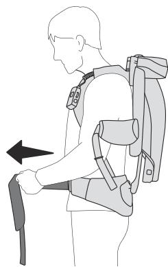
- When setting down the exoskeleton, always hold it by the carrying strap [1-8] and set it down with care. Otherwise, the exoskeleton could become damaged.
Prevent damage due to falling. The exoskeleton must be checked after falling to see whether any parts are damaged and whether it is working. - Keep packaging film away from children. There is a risk of suffocation.
-
Also follow the operating manual for the battery pack and the charger of further Festool power tools that are used when working with the exoskeleton.
-
Comply with the safety regulations that apply in your country.
2.2 Emission levels
The determined values are:
Sound pressure level L_PA < 70 dB( A)
Whole body vibration a < 0.5 ~m / s^2
Total measured value for vibration a_hv < 2.5 m/s^2
3 Intended use
The exoskeleton is suitable for supporting the shoulder musculature during work in a vertical direction that takes place in front of the chest and overhead. It supports applications like sanding of primed drywall constructions and ceilings, and wallpapering and painting of walls and ceilings.
The operating temperature range is 0^ C to 40^ C .
The exoskeleton is exclusively intended for the use of persons with a head size of 160 cm-200 cm.
The exoskeleton is not suitable for
supporting work in a horizontal movement,
supporting persons whose constitutions would not allow them to perform the work without an exoskeleton,
supporting persons who can operate the exoskeleton only to a limited extent or who cannot read and understand the operating manual,
- circumventing maternity protection measures.
The user is liable for improper or non-intended use.
4 Technical data
| Exoskeleton | Exo 18 | |
| Rated voltage | 18 V = | |
| Rated current | 4 A | |
| Frequency band | 2402-2480 MHz | |
| Equivalent isotropically radiated power (EIRP) | < 10 dBm | |
| Transport dimensions | 835 mm x 365 mm x 775 mm | |
| Compatible battery packs | Festool BP 18 Li ≥ 3.1 Ah | |
| Weight of exoskeleton excl. battery pack | 7 kg | |
5 Device description
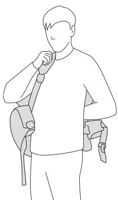
The exoskeleton is used to support the shoulder and neck muscles with work-related arm movements and load handling in front of the chest and above head height.
The exoskeleton is worn on the back here, similarly to a hiking backpack, and secured to the body with the lap strap [1-13], the belt system [1-10], the chest strap [1-4] and the armrests [1-3]. During operation, a vertical support force is introduced into the upper arm via the armrests, in order to reduce the load on the shoulder and neck muscles. Two headrests of different heights [1-9] can be optionally used to lean the head against during work, thereby increasing comfort during overhead work.
The exoskeleton is controlled via the control module [1-11]. Energy is supplied via the battery pack [1-16].
The textile system can be removed from the exoskeleton and can be washed separately in a wash bag [1-1].
The packaging [1-17] is used to transport and put down the exoskeleton, for instance while setting the size.
5.1 Parts of the device
[1-1] Wash bag
[1-2] Magnetic closure of the armrest pads
[1-3] Armrests
[1-4] Chest strap
[1-5] Exo arm
[1-6] Quick-action clamp
[1-7] Joint chain
[1-8] Carrying loop
[1-9] Two headrests of different heights
[1-10] Belt system
[1-11] Control module
[1-12] Blade lock
[1-13] Lap strap
[1-14] Capacity indicator
[1-15] Buttons to release the battery pack
[1-16] Battery pack
[1-17] Packaging
The illustrations specified are located at the beginning and end of the operating instructions.
6 Battery pack
Before using the battery pack, check that the battery interface is clean. Any contamination of the battery interface may impair correct contact and lead to the contacts being damaged.
A faulty contact may result in the machine overheating or being damaged.
[2A] Remove the battery pack.
[2B] click
Insert the battery pack – until it clicks into place.
Further information about the charger and battery pack with capacity indicator can be found in the corresponding operating manual.
7 Commissioning

CAUTION
Risk of injury
- Carry out function testing before each commissioning or after a fall. If there is damage to the exoskeleton, it must not be started up.
- Check that the exoskeleton is complete before each commissioning.
7.1 Headrest
i Recommendation: Use a headrest when performing work overhead.
Choose whichever headrest seems most comfortable to you for the respective activity.
Installing a headrest [3A]
Put the headrest [3-1] on and press until it engages.
Removing the headrest [3B]
- Lift the headrest and remove it from the exoskeleton.
7.2 Compatibility test
The maximum support force of the exoskeleton is designed so that healthy persons can overcome it with their own muscular strength in the event of an emergency.
The movement radii of the exoskeleton are within the movement limits of persons without physical (joint) limitations. This ensures that
English
overextension of joints cannot occur in healthy persons.
Nevertheless, for reasons of safety, test that the device is compatible with your physical condition.
Position the exoskeleton (do not switch on).
- All possible movements that can be performed with the exoskeleton must be tested once.
If all movements can be realised without difficulty, then the exoskeleton can be switched on. Contact customer service in the event of doubt.
8 Settings
8.1 Control module
The following settings can be set and adjusted using the control module [4]:
- Set power assistance (see section 8.2).
- Connection with Festool Work App (see section 8.4).
Selection of a profile (see section 8.6).
Activation and deactivation of pause mode (see section 9.7).
8.2 Setting power assistance
The exoskeleton has five power levels.
| Power levels | |
| 0 | Off, no support |
| 1 – 2 | Slight power assistance |
| 2 – 3 | Medium power assistance |
| 4 – 5 | Strong power assistance |
8.3 Angle compensation
The exoskeleton recognises whether you are standing upright or bending forwards, for instance.
To prevent unwanted support in certain situations, the power assistance of the exoskeleton adapts itself to your posture. In extreme postures, this may even lead to power assistance switching off completely.
8.4 Connection with Festool Work App*
A mobile end device (e.g. smartphone) can be connected with the exoskeleton via Bluetooth®.
- Open Festool Work App.
Press the Bluetooth® button [4-7] until the Bluetooth® LED [4-8] flashes blue
The exoskeleton is ready for connection for 60 seconds.
-
Follow the instructions provided in Festool Work App to authorise the secure connection.
You can find further information about operating and configuring the exoskeleton in Festool Work App. -
Not available in all countries.
8.5 Expanded range of functions: Festool Work App
The exoskeleton has further functions, which can be set via Festool Work App. Festool Work App also offers further information on the following topics:
- Tutorials (e.g. help with putting on)
- Operating data regarding the exoskeleton
- Operating data regarding the battery pack
- Software updates
- Accessories
- Warranty and service information
Information on last contact with the exoskeleton
For this, connect your exoskeleton with the Festool Work App on your mobile end device (see section 8.4).
8.6 Selection of a profile
The exoskeleton has three preconfigured profiles, which can be selected on the control module by pressing the profile button [4-1].
The green LED of the profile display [4-9] shows the set assistance range.
| Profile display | Assistance range |
| 1 Working on ceilings (Overhead) | 2 Working on walls (From chest height) |
| 3 Standard profile (Waist up) | Further profiles |
(i) Power assistance must be adjusted after changing a profile.
8.7 Temperature cut-out
The exoskeleton recognises if the temperatures of the compressor and battery pack are too high or too low. If the temperature deviates too far, the compressor no longer starts, power
assistance is reduced and/or the exoskeleton switches itself off.
The status indicator [4-3] shows the respective state. For a further course of action, see section 10.
9 Working with the exoskeleton
9.1 Safe working

When working on the machine, observe all of the safety warnings that are listed start as well as the following rules:
Before starting
- Switch the exoskeleton on only after you have put it on as described in section 9.5.
- Before working with the exoskeleton, check that all removable parts (see section 13.2) are correctly installed.
Perform a compatibility test (see section 7.2).
Check before working with the exoskeleton that you can overcome the resistance in all joint positions even at the highest power setting.
If the power of the exoskeleton exceeds your own power, unexpected movements can be hazardous to you or to persons standing in the vicinity.
- Test whether you can perform all actions required for your planned work with the exoskeleton.
Do not perform any work that can be performed only with difficulty or to a limited extent with the exoskeleton. - Do not carry any objects that you cannot carry independently without the power assistance of the exoskeleton.
- Check whether you can fully control the exoskeleton at all times, including when wearing work clothing and personal protective equipment.
- Check it's set to the correct size before starting work. An exoskeleton not correctly adapted to your body size and wrinkles in your clothing when wearing the exoskeleton can cause skin irritations.
During work
-
There is a risk of crushing between the exo arm [1-5] and joint chain [1-7]. Do not reach into this area. Keep persons standing in the vicinity away from this area.
-
Never guide the power cable over the joint chain when working with mains-powered power tools [1-7].
- Keep the armrests [1-3] closed in work mode.
- Only adjust the power assistance slowly and gradually.
- Should you experience sensory disturbances or pain during work, the exoskeleton must be put down and medical advice obtained.
9.2 Setting the size

CAUTION
Risk of injury due to joint chain
Crushing of the hands
- Do not reach into the area of the joint chain [1-7] or between the joint chain and exo arm [1-5].
Set the size before you put on the exoskeleton.
Setting the back length [5A]
Determine the setting of your back length based on your body size and using the table in image [6].
Pull and hold the little flag [5-1] in order to release the blade lock [5-4].
Push the blade until your determined back length appears on the scale [5-3] on the edge of the body [5-2].
Release the little flag.
The blade lock engages.
Setting shoulder width [5B]
Determine the setting of your shoulder width based on your body size and using the table in image [6].
On both sides:
Open the quick-action clamp [5-5].
Push the joint chain [5-6] on the gripping surface [5-9] until your determined shoulder width appears on the scale [5-8] on the edge of the body [5-7].
Close the quick-action clamp.
Setting armrests [5C]
On both sides:
Press and hold the button [5-10].
Set the position of the armrests by pushing them in the groove.
- Release the button.
The armrest engages.
9.3 Inserting the battery pack
Insert the battery pack (see section 6).
i After inserting the battery pack, the exoskeleton is in stand-by mode.
9.4 Identification of the belts/straps
Position adjustment strap
Shoulder belt
Lap belt
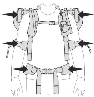
9.5 Putting on and readjusting the exoskeleton
CAUTION! Do not reach into the area of the joint chain [1-7]. Also point this out to persons who may be helping you with positioning.
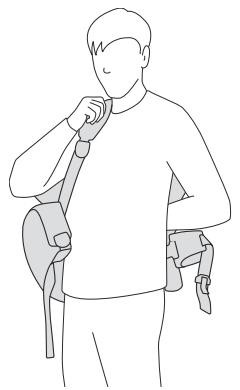
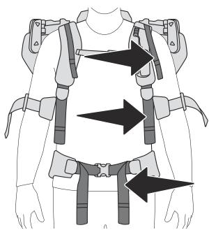
Put on the exoskeleton like a rucksack. When doing so, put on the shoulder straps without tightening the shoulder belts.
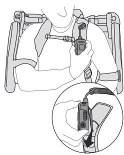
Hook the control element into the holder of the shoulder strap.

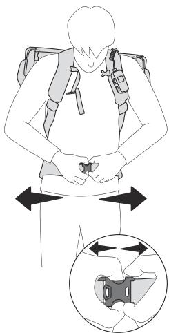
Slightly tighten the shoulder belts until the lap strap is lying on your pelvic bones.
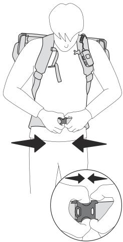
Close the lap strap.
The lap strap is covering the pelvic bones and the closure of the lap strap sits below the navel.
- Tighten the lap belts.
The weight of the exoskeleton lies on your lap.
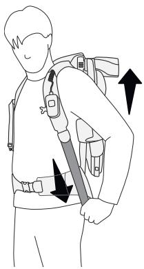
Slightly tighten the shoulder belts to comfortably stabilise the exoskeleton on the body.
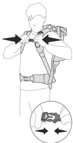
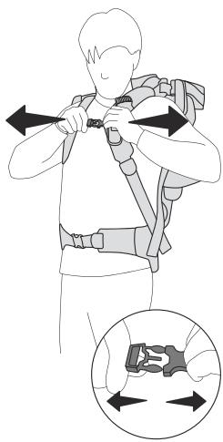
- Close the chest strap and slightly tighten the position adjustment straps.
Pull the exoskeleton towards your back with the position adjustment straps.
Shoulder position
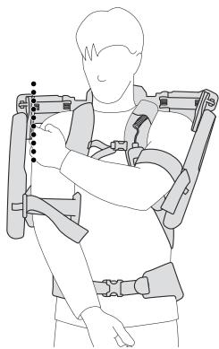
Checking the shoulder width: There is a distance of approx. 1-2 cm between each of the shoulders and the exoskeleton.
CAUTION! If the exoskeleton is not sitting correctly, the size of the shoulder width on the exoskeleton must be reset (see section 9.2).
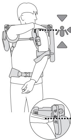
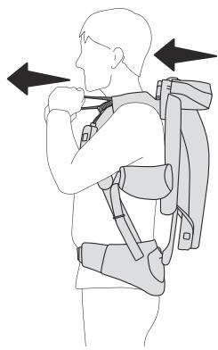
- Checking the shoulder height: Place your hand on your shoulder. Your hand must be located in the area of the position marking.
CAUTION! If the exoskeleton is sitting too high or too low, the set size of the back length must be corrected (see section 9.2).
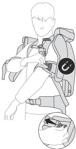
Armrests
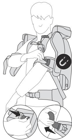
Place your arms in the armrests and close the armrests with the magnetic closures.
Slightly tighten the rubber straps of the armrests.
CAUTION! It must be possible for the arms to be moved freely in the armrests.
CAUTION! Should rubber straps being tightened too tightly lead to sensory disturbances or pain in hands or fingers, loosen the rubber straps of the armrests. If the sensory disturbances or pain will not ease, the exoskeleton must be put down and medical advice obtained.
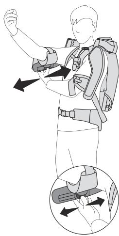
- Checking the armrest position: With horizontal arms and elbows bent facing upwards, a distance of approx. four finger-widths should remain between the elbow and the armrest. The rubber straps of the armrests must not cut into the bends of the elbows here.
CAUTION! If the exoskeleton is not sitting correctly, the size of the armrests must be reset on the exoskeleton (see section 9.2).
CAUTION! Store the loops of the belts in the belt guides. Loops that are hanging down can be caught by the exoskeleton and lead to falls or crushing.
9.6 Checking the fit
Are your shoulders in the area of the position markings?
The armrests are sat comfortably, are not constricting and are not pressing against your elbow?
Is the lap strap covering the pelvic bones?
9.7 Switching on

WARNING
Risk of injury
- Risk of injury from uncontrolled movements of the exoskeleton.
- Switch the exoskeleton on only after you have put it on as described in section 9.5.
'Ready for operation' mode
Press the On/Off button [4-4] for approx. one second. The accumulator is filled.
The status indicator [4-3] lights up green. The exoskeleton is ready for operation.
The profile display [4-9] shows whichever profile is set.
The most recently selected setting is set as standard after switching on.
Work mode
Turn power regulation [4-5] clockwise.
The exoskeleton supports work with the set power. The power of the assistance is depicted via the power display [4-2].
If the power assistance is turned to zero, the exoskeleton switches back to 'ready for operation' mode.
Pause mode
Pressing the pause button [4-6] switches the exoskeleton to pause mode. The power assistance sinks to zero and the power display [4-2] flashes. Pressing the pause button again switches the exoskeleton back to work mode, and the previously set power is reactivated.
CAUTION! The exoskeleton must not be put down when it's in pause mode. Switch off the exoskeleton via the On/Off button [4- 4] before you put it down.
9.8 Switching off
Press the On/Off button [4-4] for approx. one second.
i If the exoskeleton is in work or pause mode and the arms do not move for longer than 1.5 minutes, the exoskeleton switches to standby mode.
If the exoskeleton is in 'ready for operation' mode and the arms do not move for longer than ten minutes, the exoskeleton likewise switches to standby mode.
Standby mode
Standby mode corresponds to the "Switched off" state with a battery pack that is in use.
9.9 Removing the exoskeleton
- Switch off the exoskeleton at the control module (see section 9.8)
- Open the magnetic closure on the armrests by pulling on the green straps.
- Open the chest strap by pressing the buckle parts.
- Open the lap strap by pressing the buckle parts.
Remove the exoskeleton like a rucksack.
Put the exoskeleton down on the packaging or on a flat surface.
9.10 Removing the battery pack
- Switch off the exoskeleton at the control module (see section 9.8)
Remove the battery pack (see section 6).
10 Status indicator
| Status indicator [4-3] | Cause | Action |
| LED lights up green. | ‘Ready for operation' mode or work mode | |
| LED flashes yellow three times. | The battery pack charge is low. The lower the charge, the shorter the intervals until it next flashes. | Charge the battery pack (see section 6). |
| Power assistance switches off. | Speed monitoring/excessive speed of arm movements. | |
| LED stays off for two seconds. | The exoskeleton is in a position that is not permitted. | |
| LED flashes yellow twice. | ||
| Power assistance switches off. | The battery pack is empty. | Charge the battery pack (see section 6). |
| LED stays off for two seconds. | ||
| LED flashes yellow three times. | ||
| The exoskeleton switches off. | ||
| Power assistance switches off. | Battery pack at excessive temperature. | Let the battery pack cool down. Switch on the exoskeleton again. |
| LED stays off for two seconds. | Insufficient battery pack or compressor temperature. | Wait until the temperature has risen back to >0 °C. |
| LED flashes red three times. | Switch on the exoskeleton again. | |
| The exoskeleton switches off. | ||
| LED flashes red and green alternately. | Compressor at excessive temperature. | Allow the exoskeleton to cool down until the compressor is re-pumping again. |
| The compressor is not re-pumping. | ||
| LED lights up red. | Fault | Further information in the Festool Work App. |
| Power assistance switches off. | If the fault persists, contact an authorised service workshop or the manufacturer. | |
| The exoskeleton switches off. | ||
| Off | The exoskeleton is deactivated or is in stand-by mode. | Insert the battery pack if necessary (see section 6) and switch on the exoskeleton (see section 9.7). |
11 Behaviour in the event of faults or accidents
After a fault or an accident, contact an authorised service workshop or the manufacturer before recommissioning the exoskeleton.
i Observe the information on the status indicator [4-3] in section 10.
11.1 Power assistance cannot be turned down via power regulation [4-5].
Try the following options, carefully putting down all hand-held objects beforehand: - Switch off the exoskeleton at the On/Off button [4-4].
English
- Ask another person to remove the battery pack. This causes the support force to be withdrawn immediately.
- Ask another person to hold the armrest in the top position while you put down the exoskeleton. Remove the battery pack after putting the exoskeleton down.
11.2 Smoke or strong heat development
- Switch off the exoskeleton immediately at the 0 ~n / 0 ~f f button and then put it down.
Remove the battery pack.
11.3 Unusual noises
- Switch off the exoskeleton immediately at the 0 ~n / 0 ~f f button and then put it down.
Remove the battery pack.
11.4 Jammed textiles or other materials
- Switch off the exoskeleton immediately at the On/Off button and then put it down.
- Remove the battery pack before trying to remove jammed objects.
- Be aware that the removal of jammed objects may lead to a renewed risk of jamming. Jammed objects could impact the functioning of the device, even after the jammed object has been removed. Contact customer service if there is any suspicion of this.
11.5 Breaking off of parts
In the event of collisions with other objects, parts of the exoskeleton could break off or tear components. This damage could impact the safe operation of the exoskeleton.
- Switch off the exoskeleton immediately at the 0 ~n / 0 ~f f button and then put it down.
Remove the battery pack. - Contact customer service for a further course of action.
11.6 Tears in textile components
Tears in the textile components could impact the safe operation of the exoskeleton.
- Switch off the exoskeleton immediately at the On/Off button and then put it down.
Remove the battery pack. - Contact customer service for a further course of action.
12 Transport and storage
- Only transport or store the exoskeleton with battery packs that have been removed.
Transport the exoskeleton by the carrying strap [1-8] and set it down with care.
Remove the lap strap [8B] to avoid damage to it (see section 13.3).
Dry damp textiles before packing (for removing textiles, see section 13.3).
- Store the exoskeleton in the packaging [1-17] in a dry room at -20^ to 60^ .
13 Service and maintenance

WARNING
Risk of injury from electric shock
Always remove the battery pack from the exoskeleton before performing any maintenance or service work.
- All maintenance and repair work which requires the housing to be opened should always be carried out by an authorised service workshop.
Customer service and repairs must only be carried out by the manufacturer or service workshops. You must only use original Festool spare parts.
Further information: www.festool.co.uk/service
In order to maintain technical safety, the valve unit must be replaced with an original spare part by a recognised specialist workshop every five years or at least after 5000 operating hours.
Damaged safety devices and components must be repaired or replaced in a recognised specialist workshop, unless otherwise indicated in the operating instructions.
To ensure constant air circulation, always keep the cooling air openings in the housing clean and free of blockages.
Vacuum and wipe the inside and outside of the exoskeleton and the headrests to clean them.
13.1 Readjusting the shoulder width setting quick-action clamp
The clamping force of the shoulder width setting [7-3] quick-action clamp can change over the course of time.
- Readjust the quick-action clamps at the screws [7-2] with a T30 star key [7-1], so that the quick-action clamps are properly closed, and the shoulder width setting is securely locked as a result.
13.2 Replacing or cleaning textiles
The belt system and the armrest pads can be replaced or removed for cleaning.
Washing symbols

Wash in wash bag.

Wash very gently at 30^ C .
Do not tumble dry.

Do not dry in the drum dryer.

Do not iron.
13.3 Removing textiles
[8A] Removing a control element
- ① Open the snap fasteners on the textile cable guide.
Remove the control element from the holder on the shoulder strap and set it aside.
[8B] Undoing the lap strap
1 Open the clamp lever.
Remove the lap strap at the ball joint.
[8C] Undoing clips
Pull and hold above the back mesh at the eyes of the locking bolts.
Remove the clips.
[8D] Removing the back mesh
Unhook the mesh loops.
The harness can be removed from the exoskeleton.
[8E] Removing armrest pads
- Remove the magnetic closures from the rubber strap and store securely, e.g. on the magnetic counterpartpiece of the closure.
Fold down the sides of the armrest pads.
Remove the armrest pads from the armrests.
Thread the rubber straps out of the armrests.
13.4 Installing textiles
[9A] Securing armrest pads
- Thread the rubber straps into the armrests.
- Place the armrest pads on the armrests. The short side of the armrest pads is on the sides with the magnetic closure.
- Place the armrest pads over the armrests. Fold the sides of the armrest pads around the armrests.
Secure the magnetic closures to the rubber straps.
[9B] Securing the lap strap
Insert the lap strap at the ball joint.
Close the clamp lever.
[9C] Securing the back mesh
Relax the buckles of the back mesh.
Hook in the mesh loops.
[9D] Closing clips
Pull and hold the eyes of the locking bolts.
Push the clips of the belt system into the clip holder of the exoskeleton.
Release the eyes. The locking bolts engage.
Tension the back mesh by pulling on the carrying loop.
[9E] Securing a control element
Hook the control element into the holder on the shoulder strap.
- Place the cable of the control element in the textile cable guide on the shoulder strap, and close the snap fasteners.
14 Accessories
You can find the PO numbers for accessories and tools under www.festool.co.uk.
15 Environment

Do not dispose of the device in the household waste! Recycle devices, accessories and packaging. Observe appli-national regulations.
Before disposal, users must remove discharged batteries, accumulators that are not enclosed by the device and lights that can be removed from the old device without causing damage, if these are present. The old batteries and rechargeable batteries can then be recycled systematically.
In accordance with the European Directive on waste electrical and electronic equipment and implementation in national law, used power tools must be collected separately and handed in for environmentally friendly recycling.
Information on collection points for proper disposal can be found at www.festool.co.uk/ recycling.
Information on REACH: www.festool.co.uk/ reach
16 General information
16.1 Information about Bluetooth®
The tool can be connected to a mobile device via Bluetooth®. As soon as the tool is connected to Festool Work App via Bluetooth® and the secure connection has been authorised, the tool will connect automatically to Festool Work App from this point onwards. The tool then regularly sends status information (ID, operating status, etc.) via Bluetooth®.
The Bluetooth® word mark and the logos are registered trademarks of Bluetooth SIG, Inc.; they are used by TTS Tooltechnic Systems AG & Co. KG, and therefore by Festool, under licence.
16.2 Information on data privacy
The power tool contains a chip which automatically stores machine and operating data. The data saved cannot be traced back directly to an individual.
The data can be read in a contactless manner using special devices and shall only be used by Festool for fault diagnosis, repair and warranty processing and for quality improvement or enhancement of the power tool. The data shall not be used in any other way without the express consent of the customer.
Imported into the UK by
Festool UK Ltd
1 Anglo Saxon Way
Bury St Edmunds
IP30 9XH
Great Britain
Sommaire
i Exoskeleton ma 5 stapn'sily.
Radiated Power, EIRP)
< 10 dBm