LITHOS EG6 BK A45 - 110.0255.510 - Range hood FABER - Free user manual and instructions
Find the device manual for free LITHOS EG6 BK A45 - 110.0255.510 FABER in PDF.
User questions about LITHOS EG6 BK A45 - 110.0255.510 FABER
0 question about this device. Answer the ones you know or ask your own.
Ask a new question about this device
Download the instructions for your Range hood in PDF format for free! Find your manual LITHOS EG6 BK A45 - 110.0255.510 - FABER and take your electronic device back in hand. On this page are published all the documents necessary for the use of your device. LITHOS EG6 BK A45 - 110.0255.510 by FABER.
USER MANUAL LITHOS EG6 BK A45 - 110.0255.510 FABER
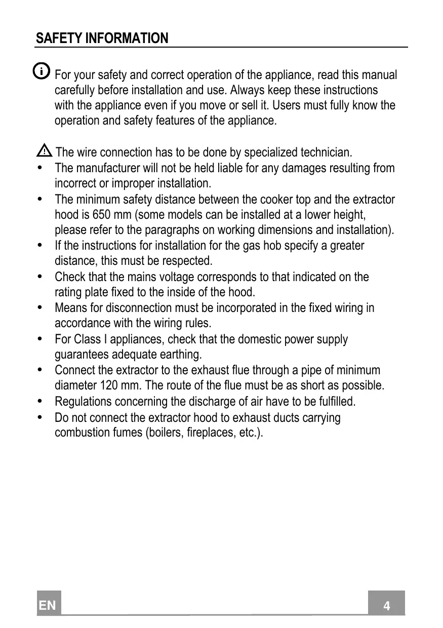
For your safety and correct operation of the appliance, read this manual carefully before installation and use. Always keep these instructions with the appliance even if you move or sell it. Users must fully know the operation and safety features of the appliance.

The wire connection has to be done by specialized technician.
- The manufacturer will not be held liable for any damages resulting from incorrect or improper installation.
- The minimum safety distance between the cooker top and the extractor hood is 650~mm (some models can be installed at a lower height, please refer to the paragraphs on working dimensions and installation).
- If the instructions for installation for the gas hob specify a greater distance, this must be respected.
- Check that the mains voltage corresponds to that indicated on the rating plate fixed to the inside of the hood.
- Means for disconnection must be incorporated in the fixed wiring in accordance with the wiring rules.
- For Class I appliances, check that the domestic power supply guarantees adequate earthing.
- Connect the extractor to the exhaust flue through a pipe of minimum diameter 120 ~mm . The route of the flue must be as short as possible.
- Regulations concerning the discharge of air have to be fulfilled.
-
Do not connect the extractor hood to exhaust ducts carrying combustion fumes (boilers, fireplaces, etc.).
-
If the extractor is used in conjunction with non-electrical appliances (e.g. gas burning appliances), a sufficient degree of aeration must be guaranteed in the room in order to prevent the backflow of exhaust gas. When the cooker hood is used in conjunction with appliances supplied with energy other than electric, the negative pressure in the room must not exceed 0,04 mbar to prevent fumes being drawn back into the room by the cooker hood.
- The air must not be discharged into a flue that is used for exhausting fumes from appliances burning gas or other fuels.
- If the supply cord is damaged, it must be replaced from the manufacturer or its service agent.
- Connect the plug to a socket complying with current regulations, located in an accessible place.
- With regards to the technical and safety measures to be adopted for fume discharging it is important to closely follow the regulations provided by the local authorities.
WARNING: Before installing the Hood, remove the protective films.
- Use only screws and small parts in support of the hood.
WARNING: Failure to install the screws or fixing device in accordance with these instructions may result in electrical hazards.
- Do not look directly at the light through optical devices (binoculars, magnifying glasses...).
- Do not flambé under the range hood; risk of fire.
- This appliance can be used by children aged from 8 years and above and persons with reduced physical, sensory or mental capabilities or lack of experience and knowledge if they have been given supervision or instruction concerning use of the appliance in a safe way and understand the hazards involved. Children shall not play with the appliance. Cleaning and user maintenance shall not be made by children without supervision.
- Children should be supervised to ensure that they do not play with the appliance.
- The appliance is not to be used by persons (including children) with reduced physical, sensory or mental capabilities, or lack of experience and knowledge, unless they have been given supervision or instruction.
Accessible parts may become hot when used with cooking appliances. - Clean and/or replace the Filters after the specified time period (Fire hazard). See paragraph Care and Cleaning.
- There shall be adequate ventilation of the room when the range hood is used at the same time as appliances burning gas or other fuels (not applicable to appliances that only discharge the air back into the room).
- The symbol on the product or on its packaging indicates that this product may not be treated as household waste. Instead it shall be handed over to the applicable collection point for the recycling of electrical and electronic equipment. By ensuring this product is disposed of correctly, you will help prevent potential negative consequences for the environment and human health, which could otherwise be caused by inappropriate waste handling of this product. For more detailed information about recycling of this product, please contact your local city office, your household waste disposal service or the shop where you purchased the product.

"In case of replacement with halogen lamp use only self-shielded tungsten halogen lamps or self-shielded metal halide lamps."
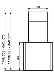
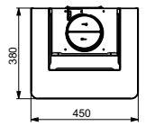
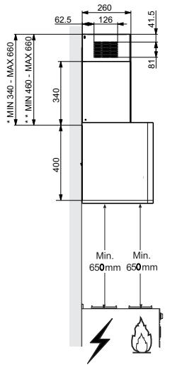
- Dimensions of the hood in ducting version.
** Dimensions of the hood in recycling version.
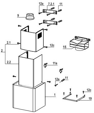
Components
| Ref. | Q.ty | Product Components |
| 1 | 1 | Hood Canopy, complete with: Controls, Light, Fan unit, Filters |
| 2 | 1 | Telescopic chimney, comprising: |
| 2.1 | 1 | Upper chimney |
| 2.2 | 1 | Lower chimney |
| 9 | 1 | Reduction flangeø 150-120 mm |
| 15 | 1 | Air Outlet Connector |
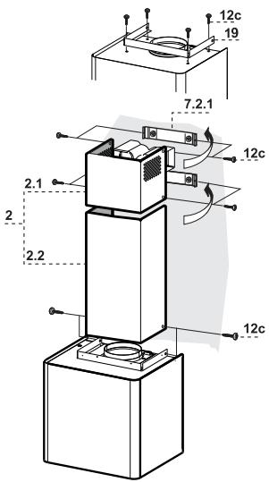
| 19 | 1 | Chimney Fixing Element |
| Ref. | Q.py | Components for Installation |
| 7.2.1 | 2 | Upper Chimney Fixing Brackets |
| 11 | 5 | Plugs |
| 11a | 2 | Plugs SB 12/10 |
| 12a | 5 | Screws 4.2 x 44.4 |
| 12c | 10 | Screws 2.9 x 6.5 |
| Q.py | Documentation | |
| 1 | Instruction Manual |
Drilling the Wall
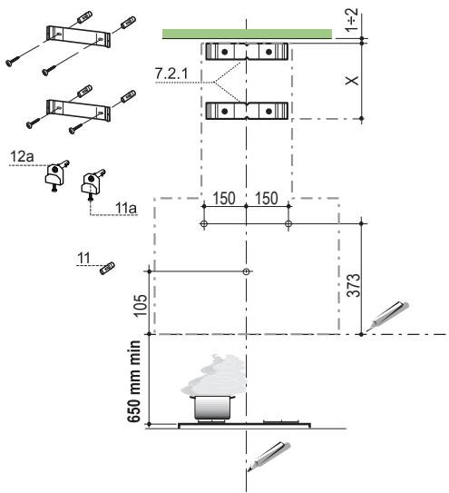
Mark the following on the wall:
- a vertical line up to the ceiling or surface above the hood, at the centre of the area in which the hood itself is to be fitted;
- a horizontal line at: 650 ~mm min. above the Hob;
- Rest the Bracket 7.2.1 as indicated, 1 - 2mm from the ceiling or surface above the hood, aligning its centre (grooves) with the vertical reference line.
- Mark the centres of the holes in the bracket.
- Rest the Bracket 7.2.1 as indicated, X mm under the first bracket ( X = height of the Upper chimney provided), aligning its centre (grooves) with the vertical reference line.
- Mark the centres of the holes in the bracket.
- Mark a reference point as indicated at 105mm from the horizontal reference line.
- Drill the points marked using an 8mm bit.
- Insert the plugs 11 into the holes.
Fix the Brackets, using the screws 12a (4.2 x 44.4) provided. - As indicated above, mark a reference point 373mm above the horizontal reference line, and 150mm to the right of the vertical reference line.
- Repeat this operation on the opposite side, checking to ensure it is level.
- Drill the points marked using an 12mm bit.
-
Insert the plugs, screws and bracket 11a into the holes, and fasten.
-
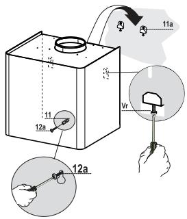
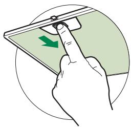
Remove the metal grease filters by turning the handles provided.
- Adjust the two screws Vr , on brackets 11a, to a minimum.
- Hook the hood canopy onto the two brackets 11a.
- From inside the hood canopy, adjust the screws Vr to set the Hood Canopy level.
- Tighten the safety screws 12a.
Connections
DUCTED VERSION AIR EXHAUST SYSTEM
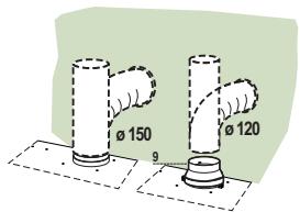
When installing the ducted version, connect the hood to the chimney using either a flexible or rigid pipe 150 or 120mm the choice of which is left to the installer.
- To install a 120mm air exhaust connection, insert the reducer flange 9 on the hood body outlet.
Fix the pipe in position using sufficient pipe clamps (not supplied). - Remove possible charcoal filters.
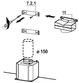
AIR OUTLET - RECIRCULATION VERSION
- Unfasten the 2 screws fixing the upper bracket 7.2.1.
- Fasten the air outlet connector 15 in its place, using the 2 screws removed as above.
- Join the Connector 15 to the Hood canopy outlet using a rigid or flexible pipe 150mm , selection of which is at the discretion of the installation technician.
- Make sure that the Activated charcoal odour filter has been fitted.

ELECTRICAL CONNECTION
- Connect the hood to the mains through a two-pole switch having a contact gap of at least 3mm .
- Remove the grease filters (see paragraph Maintenance) being sure that the connector of the feeding cable is correctly inserted in the socket placed on the side of the fan.
Chimney Assembly
- Fasten the Chimney fixing element 19 to the Body using 4 screws 12c.
Upper chimney
- Open the two side pieces out slightly, hook them up behind the brackets 7.2.1 and bring them back together again until they are in contact.
Fix to the Brackets at the sides, using 4 screws 12c (2.9 x 9.5) provided. - If there are any, make sure that the Connector extensions outlet is in correspondence with the Chimney openings.
Lower chimney
- Open the two side pieces of the Chimney out slightly, hook them between the upper chimney and the wall, and then close them together again until they are in contact.
Fix the part at the sides to the Chimney fixing element 19, using 2 screws 12c (2.9 x 9.5) provided.

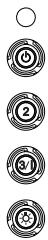
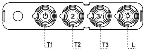
Control panel
| BUTTON | LED | FUNCTIONS |
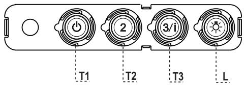
| T1 Speed | On | Turns the Motor on at Speed one. |
| Turns the Motor off. | ||
| T2 Speed | On | Turns the Motor on at Speed two. |
| T3 Speed | Fixed | When pressed briefly, turns the Motor on at Speed three. |
| Flashing | Pressed for 2 Seconds. | |
| Activates Speed four with a timer set to 6 minutes, after which it returns to the speed that was set previously. Suitable to deal with maximum levels of cooking fumes. | ||
| L Light | Turns the Lighting System on and off. |
Warning: Button T1 turns the motor off, after first passing to speed one.
Grease filters
CLEANING METAL SELF- SUPPORTING GREASE FILTERS
- The filters must be cleaned every 2 months of operation, or more frequently for particularly heavy usage, and can be washed in a dishwasher.
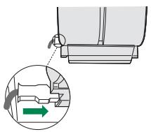
- Remove the filters one at a time by pushing them towards the back of the group and pulling down at the same time.
- Wash the filters, taking care not to bend them. Allow them to dry before refitting.
- When refitting the filters, make sure that the handle is visible on the outside.
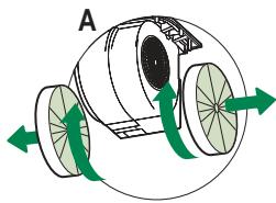
Activated charcoal filter (Recirculation version)
These filters are not washable and cannot be regenerated, and must be replaced approximately every 4 months of operation, or more frequently with heavy usage.
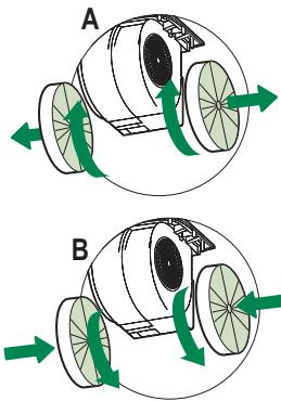
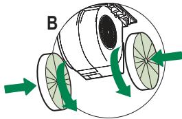
REPLACING THE ACTIVATED CHARCOAL FILTER
- Remove the metal grease filters
- Remove the saturated activated charcoal filter as shown (A).
- Fit the new filters (B).
- Replace the metal grease filters.
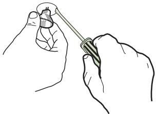
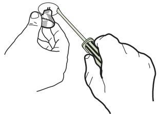
LIGHT REPLACEMENT
20 W halogen light.
- Extract the lamp from the lamp holder by pulling gently.
- Replace with another of the same type, making sure that the two pins are properly inserted in the lamp holder socket holes.
| Lamp | Power (W) | Socket | Voltage (V) | Dimension (mm) | ILCOS Code |
| 28 | E14 | 220 – 240 | 104 x 35 | HSGSB/C/UB-28-220/240-E14 | |
| 28 | E14 | 230 | 85x25 | HDG-28-230-E14-25 | |
| 20 | G4 | 12 | 33 x 9 | HSG/C/UB-20-12-G4 | |
| 35 | GU10 | 230 | 51 x 50,7 | HAGS-35-230-GU10-51/40 | |
| 50 | GU10 | 230 | 51 x 50,7 | HAGS-35-230-GU10-51/20 | |
| 20 | GU4 | 12 | 40 x 35 | HRGS-20-12-GU4-35/30 | |
| 20 | GU5.3 | 12 | 46 x 51 | HRGS-20-12-GU5.3-50/10 | |
| 16 | G13 | 95 | 720 x 26 | FD-16/40/1B-E-G13-26/720 | |
| 18 | G13 | 57 | 589,8 x 26 | FD-18/40/1B-E-G13-26/600 | |
| 9 | G23 | 60 (lamp) 220-240 (starter) | 167 x 28 | FSD-9/27/1B-I-G23 | |
| 11 | G23 | 91 (lamp) 220-240 (starter) | 235,8 x 28 | FSD-11/40/1B-I-G23 |
i
REEMPLACEMENT FILTRE AU CHARBON ACTIF
REEMPLACEMENT LAMPES
* Aiaotaoeic yia movtelo aTaywyns.
** Diaotaoeic yia movteo avakukwongs.
Egptnmuata
BbIpyCK BO3dYXA I3 BCACbIBAIOUeE BbITJXKIN
IyctaHOBKN BcacbIBaIOe BbITKaKn COeHHHTb ee c BbIyckHOI Tpy60J KecTKoH HIN r6KO Tpy60K JHaMeTpOM 150 HIn 120 MM, TII KOTopoM MoKet BbIbpaTb MOHTaKHNK.
-ⅡHcoeHHHeHH Tpy6KoI 120 MM BCTaBbIb IepexOJIbI bIaHEI 9 B BbIyCKHO EITBePcTHe KOpIyCa BbIgKII.
3aKpeHb Ty6Ky COOTBeCTBHyIOHMn Tpy6HbIMN 3aJHMamH. Heo6xoIHMbI KpeIeXHbI MaTePHaJI He BXoIHT B KOMIIJEKT.
- BbHyTb ΦHJbTpbl OT 3aIIaXOB Ha aKTHBHOM yTJIe.

BbIpyCK BO3dYXA B PEXIMME ΦNJIbTPALIN
Pa3BnHTHe 2 BnHTa KpeIJIeHnBepxHecko6b7.2.1.
Ha ee MeCTO IIpHBHHTIe BbIIyCKHOI NaIpy6oK Bo3Jyxa 15 c IIOMOIIbIO 2 CHaTbIX BHNTOB.
- CoeHHHTe IIaTpy6ok 15 c BbIyucKbIM OTBepCTHEM B KOpIyce BbITJxKKJ XeCTKOJI HJIN IHI6KOJ Tpy6KOJ (IO yCMOTpeHHHO MOHTaXHHKA) JHaMeTpOM 150 MM.
- IIpoBepbTe HaJIHcHHe HJIbTpTa IIpoTHB 3aIIaXOB Ha aKTHBnPoBAHHOM yTJe.
3JIeKTPnueCKOE NODKNIOUcHHeNHE
- CoeINHHNtB BbITJgK Ky c ceTeBBIM HaIIpJxKeHHem, yCTaHOHB NByXIOJIIOCHbI BbIKJIIOHaTeJIb c pa3BeJeHHem KOHTAKTOB He MeHee 3 MM.
CHTbIPOTHBOKHNPOBBEi HJIbTpbl (CMOTPH pa3JeJ "YXoJ) IIOBepHTb IIpaBHJIbHOCTb IOJOKeHHraPa3BeMa IINTaHOIIeRo Ka6eJI Bpo3Etke BBITJIKN

YcTaHOBKa DbIMOXOda
- IIpHbHTHe 4 BHTaMn 12c KpeIeKhBiyTOJOK IbIMOXIOB 19 K KopIyCy BbITaKKN.
BepxHryaactbIbIMoxOda
CJIeKa pa3BeIHTe B cTOpOHbI o6e 6OKOBHHbI, 3aIIeIHTe HX 3aCKo6bI 7.2.1 I BHOBb CBeIHTe IIO yIopa.
3aKpeHNTe cKO6bI IIO 6OKaM IprHJIaRaEMbIMH 4 BnHTamn 12c (2,9 x 9,5).
- IIpoBepbTe, YTO6bI BbIXOdbI yDIIHHHTeJIe IITUepea COBIIaJH c OTBepCTHMAH DbIMOXoJa.
HnKna TaCtb DbIMOXoDa
CJIeKa pa3BeIHTe B cTOpOHb I o6e 60KOBHbI bIMOXOJa, 3aKeIITe Hx MeJy BePxHei YactbIO bIMOXOJa H cTeHOH IN BHOBcBEIHTe Do yIopa.
3aKpeIInTe c60ky HnKHiOu YacTb IbIMOXoJa K KpeIeXHOMy yTOJky IbIMOXoIOB 19 2 IIpHJIaRaEMbIMH BnHTaMH 12c (2,9 x 9,5).
IIaHeIb ynpabJeHn
J 1 J 1 J 1 J 1 J 1 J 1 J 1 J 1 J 1 J 1 J 1 J 1 J 1 J 1 J 1 J 1 J 1 J 1 J 1 J 1 J 1 J 1 J 1 J 1 J 1 J 1 J 1 J 1 J 1 J 1 J 1 J 1 J 1 J 1 J
jlll pbi gblll aayalall
jgill 1012 jblai j blll lal 1
山
(a)dalln jzjollgX)xJxJxJxJxJxJxJxJxJxJxJxJxJxJxJxJxJxJxJxJxJxJxJxJxJxJxJxJxJxJxJxJxJxJxJxJxJxJxJx
jss jss sss sss
Aaalw gail jslj cale
y j 105 aie yai bai oie
aalblaii 8 jbi
111
all 12a (4.2 x 44.4)
39 150 aIaIg c, yall gaoal baii jpa 373 aIaIg c yall abai oic jia laL
占空
aill bll 12
11a 1
Jauaasall jaaal alabw y aagaaal slalal jll
Jaa 11a aally nnnn 2 Vr .
.11a 1
aill bia jia 22d 1j 2 Vr gai jbi
.12a

y
0jwulaiydiallblallllssy jbjdall iis jie
. 150-120=
a110j(a120=)
. biaiial pa 2y jie (9) iaiaill
ailllllalllllllllllll

(jllg)Jl jy bll l 100000000000000000000000000000000000000000000000000000000000

aill
Jaaai 4 Jklll 1 j klll aal
Jai Jai Jai Jai Jai Jai Jai Jai Si
j 1
-
.(A)gaaLsJnssdalljzjj
. (B)
g( x) = y0x + y1x( 0 < y_0 < 1)
sclnl J
120 2
aB aall lala 1gila n a aall E jil 1gab r gill gai n gai al cki jic 1gals
| ILCOS √JL | (∞) | (100) | (100) | (100) | (100) |
| HSGSB/C/UB-28-220/240-E14 | 104 x 35 | 220 - 240 | E14 | 28 | |
| HDG-28-230-E14-25 | 85x25 | 230 | E14 | 28 | |
| HSG/C/UB-20-12-G4 | 33 x 9 | 12 | G4 | 20 | |
| HAGS-35-230-GU10-51/40 | 51 x 50,7 | 230 | GU10 | 35 | |
| HAGS-35-230-GU10-51/20 | 51 x 50,7 | 230 | GU10 | 50 | |
| HRGS-20-12-GU4-35/30 | 40 x 35 | 12 | GU4 | 20 | |
| HRGS-20-12-GU5.3-50/10 | 46 x 51 | 12 | GU5.3 | 20 | |
| FD-16/40/1B-E-G13-26/720 | 720 x 26 | 95 | G13 | 16 | |
| FD-18/40/1B-E-G13-26/600 | 589,8 x 26 | 57 | G13 | 18 | |
| FSD-9/27/1B-I-G23 | 167 x 28 | 60 (∞)220-240 (∞) | G23 | 9 | |
| FSD-11/40/1B-I-G23 | 235,8 x 28 | 91 (∞)220-240 (∞) | G23 | 11 |