
Pisa 60 X - Range hood FABER - Free user manual and instructions
Find the device manual for free Pisa 60 X FABER in PDF.


| Product Type | Range Hood |
| Brand | Faber |
| Model | Pisa 60 X |
| Category | Under Cabinet Hood |
| Width | 598 mm (60 cm) |
| Depth | 500 mm |
| Height | 150 mm (approx.) |
| Minimum Distance from Hob | 650 mm |
| Number of Speeds | 3 + Boost (4th) |
| Control Type | Push buttons with LED indicators |
| Light Type | LED |
| Number of Lights | 1 |
| Air Duct Diameter | 150 mm (reducible to 120 mm) |
| Grease Filter Type | Self-supporting metal |
| Grease Filter Cleaning Interval | Every 2 months (more often if heavy use) |
| Charcoal Filter Type (Recirculation) | Activated charcoal (not washable) |
| Charcoal Filter Replacement Interval | Every 4 months (more often if heavy use) |
| Power Supply Voltage | 220-240 V |
| Power Supply Frequency | 50/60 Hz |
| Installation Type | Under cabinet or wall unit |
| Material | Stainless steel |
| Included Accessories | Reducer flange Ø150-120 mm, Damper Ø150 mm, Directioned grid, Screws, Manual |
| Safety Features | Class I, minimum distance 650 mm, disconnection switch required |
| Certifications | CE |
Frequently Asked Questions - Pisa 60 X FABER
User questions about Pisa 60 X FABER
0 question about this device. Answer the ones you know or ask your own.
Ask a new question about this device
Download the instructions for your Range hood in PDF format for free! Find your manual Pisa 60 X - FABER and take your electronic device back in hand. On this page are published all the documents necessary for the use of your device. Pisa 60 X by FABER.
USER MANUAL Pisa 60 X FABER
natural_image
Technical line drawing of a rectangular industrial or mechanical component with a circular top and mounting base (no text or symbols)Instructions Manual
Brugsvejledning
Bruksanvisning
Bruksanvisning
INDEX
EN
SAFETY INFORMATION....3
CHARACTERISTICS 6
INSTALLATION....7
USE 9
MAINTENANCE 10
INDHOLD
DK
OPLYSNINGER OM SIKKERHED 12
APPARATBESKRIVELSE....15
INSTALLATION....16
BRUG 18
VEDLIGEHOLDELSE 19
INNEHÅLL
SE
SÄKERHETSINFORMATION 21
EGENSKAPER 24
INSTALLATION....25
ANVÄNDING 27
UNDERHÅLL 28
INNHOLD
NO
SIKKERHETSINFORMASJON 30
EGENSKAPER 33
INSTALLASJON 34
BRUK 36
VEDLIKEHOLD 37

For your safety and correct operation of the appliance, read this manual carefully before installation and use. Always keep these instructions with the appliance even if you move or sell it. Users must fully know the operation and safety features of the appliance.

The wire connection has to be done by specialized technician.
- The manufacturer will not be held liable for any damages resulting from incorrect or improper installation.
- The minimum safety distance between the cooker top and the extractor hood is 650 mm (some models can be installed at a lower height, please refer to the paragraphs on working dimensions and installation).
- If the instructions for installation for the gas hob specify a greater distance, this must be respected.
- Check that the mains voltage corresponds to that indicated on the rating plate fixed to the inside of the hood.
- Means for disconnection must be incorporated in the fixed wiring in accordance with the wiring rules.
- For Class I appliances, check that the domestic power supply guarantees adequate earthing.
- Connect the extractor to the exhaust flue through a pipe of minimum diameter 120 mm. The route of the flue must be as short as possible.
- Regulations concerning the discharge of air have to be fulfilled.
-
Do not connect the extractor hood to exhaust ducts carrying combustion fumes (boilers, fireplaces, etc.).
-
If the extractor is used in conjunction with non-electrical appliances (e.g. gas burning appliances), a sufficient degree of aeration must be guaranteed in the room in order to prevent the backflow of exhaust gas. When the cooker hood is used in conjunction with appliances supplied with energy other than electric, the negative pressure in the room must not exceed 0,04 mbar to prevent fumes being drawn back into the room by the cooker hood.
- The air must not be discharged into a flue that is used for exhausting fumes from appliances burning gas or other fuels.
- If the supply cord is damaged, it must be replaced from the manufacturer or its service agent.
- Connect the plug to a socket complying with current regulations, located in an accessible place.
- With regards to the technical and safety measures to be adopted for fume discharging it is important to closely follow the regulations provided by the local authorities.
⚠ WARNING: Before installing the Hood, remove the protective films.
- Use only screws and small parts in support of the hood.
⚠ WARNING: Failure to install the screws or fixing device in accordance with these instructions may result in electrical hazards.
- Do not look directly at the light through optical devices (binoculars, magnifying glasses...).
- Do not flambè under the range hood; risk of fire.
- This appliance can be used by children aged from 8 years and above and persons with reduced physical, sensory or mental capabilities or lack of experience and knowledge if they have been given supervision or instruction concerning use of the appliance in a safe way and understand the hazards involved. Children shall not play with the appliance. Cleaning and user maintenance shall not be made by children without supervision.
- Children should be supervised to ensure that they do not play with the appliance.
- The appliance is not to be used by persons (including children) with reduced physical, sensory or mental capabilities, or lack of experience and knowledge, unless they have been given supervision or instruction.
⚠️ Accessible parts may become hot when used with cooking appliances.
- Clean and/or replace the Filters after the specified time period (Fire hazard). See paragraph Care and Cleaning.
- There shall be adequate ventilation of the room when the range hood is used at the same time as appliances burning gas or other fuels (not applicable to appliances that only discharge the air back into the room).
- The symbol 📁 on the product or on its packaging indicates that this product may not be treated as household waste. Instead it shall be handed over to the applicable collection point for the recycling of electrical and electronic equipment. By ensuring this product is disposed of correctly, you will help prevent potential negative consequences for the environment and human health, which could otherwise be caused by inappropriate waste handling of this product. For more detailed information about recycling of this product, please contact your local city office, your household waste disposal service or the shop where you purchased the product.
Dimensions

Components
Ref. Q.ty Product Components
1 1 Hood Body, complete with :Controls, Light, Blower, Filters
2 1 Frame
8 1 Directioned grid
9 1 Reducer Flange ø 150-120 mm
10 1 Damper ø 150 mm
Ref. Q.ty Installation Components
12a 10 Screws
12e 2 Screws 2,9 x 9,5
12f 6 Screws 2,9 x 6,5
Q.ty Documentation
1 Instruction Manual


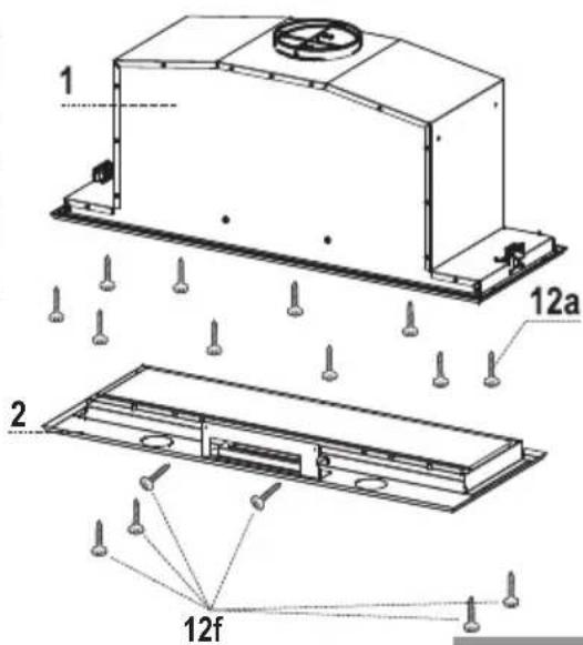
Fitting the Hood canopy
BEFORE FITTING THE HOOD TO THE WALL UNIT, PROCEED AS FOLLOWS:
- Disconnect the wires to the Commands at the connectors.
- Disconnect the wires to the Light at the connectors.
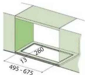
- The Hood can be installed directly on the underside of the wall unit (Minimum 650 mm from the Cooker Hob).
- Create an opening in the bottom of the wall unit, as shown.
- Insert the hood until the side supports snap into place.
- Fasten using the 10 screws 12a provided.
- Lock in position by tightening the screws Vf from underneath the hood.
- Open the suction panel by turning the specific knob.
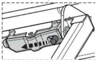
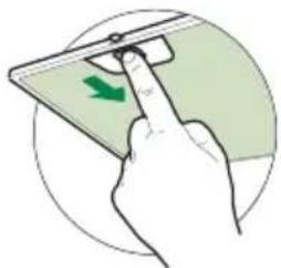
- Disconnect the panel from the hood canopy by sliding the fixing pin lever.
- Remove grease filters.
- Screw the Frame into place using the 6 screws 12f, reconnect the wires to the Commands and Light, replace the metal grease filter and the Panel.

natural_image
Hand inserting a green arrow on a smartphone screen (no text or symbols visible)
natural_image
Pure technical diagram of a rectangular frame with mounting holes and directional arrows, no text or symbols present.


natural_image
3D diagram of a mechanical housing with green directional arrows indicating movement or force (no text or symbols)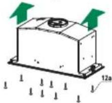
natural_image
Simple 3D diagram of a rectangular block with a circular top and two green arrows pointing upward, labeled '12a' at the base (no text or symbols on the object itself)

natural_image
Diagram showing a mechanical component with a green curved arrow indicating rotation or motion, no text or symbols present.
natural_image
Pure structural diagram of a truss structure without any text, numbers, or symbolsConnections
DUCTED VERSION AIR EXHAUST SYSTEM
When installing the ducted version, connect the hood to the chimney using either a flexible or rigid pipe 150 or 120 mm, the choice of which is left to the installer.
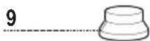
- To install a 120 mm air exhaust connection, insert the reducer flange 9 on the hood body outlet.
- Fix the pipe in position using sufficient pipe clamps (not supplied).
- Remove possible charcoal filters.
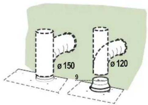
RECIRCULATION VERSION AIR OUTLET
- Cut a hole 125 mm in any shelf that may be positioned over the hood.
- Insert the reducer flange 9 on the hood body outlet.
- Connect the flange to the outlet on the shelf over the hood by using a flexible or rigid pipe 120mm .
- Fix the pipe in position using sufficient pipe clamps (not supplied).
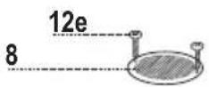
- Fix the air outlet grid 8 on the recirculation air outlet by using the 2 screws 12e (2,9 x 9,5) provided.
- Ensure that the activated charcoal filters have been inserted.

ELECTRICAL CONNECTION
- Connect the hood to the mains through a two-pole switch having a contact gap of at least 3 mm..
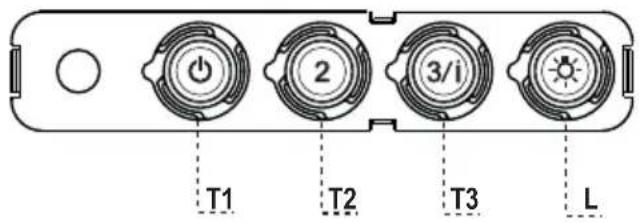

Control panel
BUTTON LED FUNCTIONS
T1 Speed On Turns the Motor on at Speed one.
Turns the Motor off.
T2 Speed On Turns the Motor on at Speed two.
T3 Speed Fixed When pressed briefly, turns the Motor on at Speed three.
Flashing Pressed for 2 Seconds.
Activates Speed four with a timer set to 6 minutes, after which it returns to the speed that was set previously. Suitable to deal with maximum levels of cooking fumes.
L Light Turns the Lighting System on and off.
Warning: Button T1 turns the motor off, after first passing to speed one.
Opening Panel
- Open the Panel by pulling it.
- Clean the outside with a damp cloth and neutral detergent.
- Clean the inside using a damp cloth and neutral detergent; do not use wet cloths or sponges, or jets of water; do not use abrasive substances.

Grease filters
CLEANING METAL SELF- SUPPORTING GREASE FILTERS
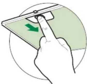
- The filters must be cleaned every 2 months of operation, or more frequently for particularly heavy usage, and can be washed in a dishwasher.
- Pull the comfort panels to open them.
- Remove the filters one by one pushing them towards the back side of the hood unit and simultaneously pulling downwards.
- Any kind of bending of the filters has to be avoided when washing them. Before fitting them again into the hood make sure that they are completely dry. (The colour of the filter surface may change throughout the time but this has no influence to the filter efficiency).
- When fitting the filters into the hood pay attention that they are mounted in correct position the handle facing outwards.
- Close the comfort panel.
natural_image
Hand inserting a green arrow on a device screen, no text or symbols visibleActivated charcoal filter (Recirculation version)
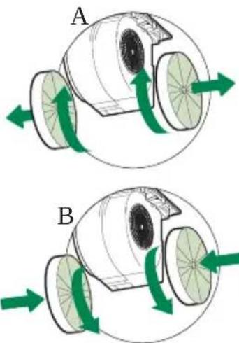
These filters are not washable and cannot be regenerated, and must be replaced approximately every 4 months of operation, or more frequently with heavy usage.
REPLACING THE ACTIVATED CHARCOAL FILTER
- Open the comfort panels pulling them downwards.
- Remove the metal grease filters
- Remove the saturated activated charcoal filter as shown (A).
• Fit the new filters (B). - Replace the metal grease filters.
- Close the comfort panels.
natural_image
Diagram of two mechanical components labeled A and B with green directional arrows indicating motion (no text or symbols beyond labels)Lighting unit
- For replacement contact technical support ("To purchase contact technical support").
Ref. Antal Installationsdele
12a 10 Skruer
12e 2 Skruer 2,9 x 9,5
12f 6 Skruer 2,9 x 6,5
Antal Dokumentation
1 Brugsanvisning


natural_image
Technical diagram of a mechanical housing or enclosure with green directional arrows indicating movement or force (no text or symbols present)
natural_image
Diagram of a mechanical component with green arrows indicating direction and 12a label, no readable text or symbols present.
natural_image
Illustration of a hand pressing a green arrow on a smartphone screen (no text or symbols)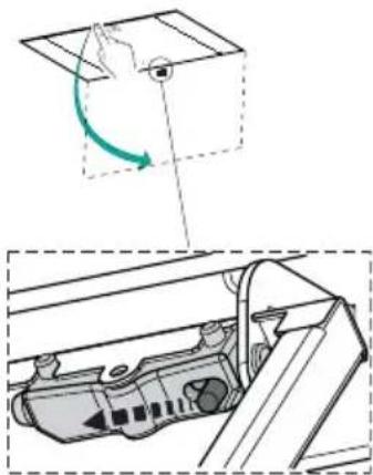
natural_image
Diagram showing a hand pressing down on a box with a green curved arrow indicating motion, and a close-up of the internal mechanical component (no text or symbols)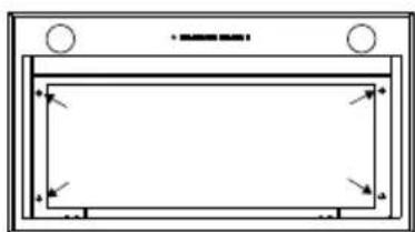
natural_image
Pure geometric diagram with nested rectangles and arrows, no text or symbols present
natural_image
Pure architectural or structural diagram showing a symmetrical frame with two inward-pointing arrows, no text or symbols present.Tilslutninger
AFSKÆRMET UDGAVE LUFTAFTRÆKSYSTEM

Betjeningspanel
TAST KONTROLLAMPER FUNKTIONER
Fedtfiltre
RENG∅RING AF SELVBÆRENDE FEDTFILTRE AF METAL
natural_image
Illustration of a hand pressing a green arrow on a device component, enclosed in a circular frame (no text or symbols)Lugtfilter med aktivt kul (Filtrerende version)
natural_image
Diagram of two mechanical components labeled A and B with green directional arrows indicating rotation or movement (no text or symbols beyond labels)Belysning
natural_image
Illustration of a hand pressing a green arrow on a smartphone screen (no text or symbols)
natural_image
Pure technical diagram of a rectangular frame with mounting holes and directional arrows, no text or symbols present.


natural_image
Technical line drawing of a mechanical housing or enclosure with green directional arrows indicating movement or force (no text or symbols)
natural_image
Diagram of a 3D rectangular block with a central circular feature and green arrows indicating direction, labeled '12a' at the base (no readable text or symbols beyond labels)

natural_image
Technical line drawing of a mechanical component or housing assembly (no text or symbols visible)
natural_image
Pure technical diagram of a structural frame with no text, numbers, or symbolsAnslutningar
ANSLUTNING AV VERSION MED FRÅNLUFTKANAL

Kontrollpanel
KNAPP LYSDIOD FUNKTIONER
Fettfilter
RENGÖRING AV SJÄLVBÄRANDE METALLFETTFILTER
natural_image
Illustration of a hand pressing a device on a screen with a green arrow indicating the left side (no text or symbols present)Luktfilter (filtrerande version)
natural_image
Diagram of two mechanical components labeled A and B with green directional arrows indicating rotation or movement (no text or symbols beyond labels)Belysning
natural_image
Three-panel image showing a connector assembly with green and black components, plus a separate close-up of a green cable (no text or symbols visible)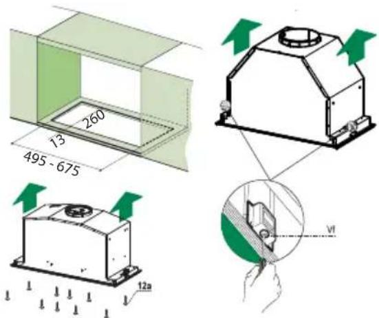
natural_image
Hand pressing a green arrow on a smartphone screen (no text or symbols visible)
natural_image
Diagram showing a mechanical component with a green curved arrow indicating rotation or motion, and an inset view of a device inside a container (no text or symbols)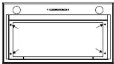
natural_image
Pure technical diagram of a rectangular frame with corner holes and directional arrows, no text or symbols present.
natural_image
Pure architectural or structural diagram showing a symmetrical frame with two inward-pointing arrows, no text or symbols present.Tilkoplinger
LUFTUTL∅P, UTSUGNINGSVERSJON
Når du skal installere en kjøkkenvifte i utsugningsversjon må du kople kjøkkenviften til utløpsrørene med et hardt eller fleksibelt rør med en diameter på 150 eller 120 mm. Installatøren kan velge hvilket rør som er mest egnet.

Kontrollpanel
KNAPP LED FUNKSJONER
| T1 Hastighet Tent Slår motoren på ved den første hastigheten. | ||
| Slår av motoren. | ||
| T2 Hastighet Tent Slår motoren på ved den andre hastigheten. | ||
| T3 Hastighet Tent konstant Trykk kort på knappen for å slå motoren på ved den tredje hastigheten. | ||
| Blinker Trykk i 2 sekunder.Aktiverer den fjerde hastigheten i 6 minutter. Når tiden er utløpt går den automatisk tilbake til den tidligere innstilte hastigheten. Egnet til å fjerne mye os. | ||
| L Lys Tenner og slukker belysningen. |
Fettfiltre
RENGJ∅RING AV DE SELVBÆRENDE METALLISKE FETTFILTRENE
natural_image
Hand holding a device with a green arrow indicating rotation (no text or symbols)natural_image
Diagram of a mechanical device with green arrows indicating rotational or directional movement (no text or symbols)
natural_image
Diagram of a mechanical device with green arrows indicating rotational flow, labeled 'B' (no text or symbols on the diagram itself)Belysning
- Kontakt kundeservice for utbytting ("Kontakt kundeservice for kjøp").
CE


- INDEX
- EN
- INDHOLD
- DK
- INNEHÅLL
- SE
- INNHOLD
- NO
- Components
- Ref. Q.ty Product Components
- Ref. Q.ty Installation Components
- Q.ty Documentation
- Fitting the Hood canopy
- BEFORE FITTING THE HOOD TO THE WALL UNIT, PROCEED AS FOLLOWS:
- Connections
- DUCTED VERSION AIR EXHAUST SYSTEM
- RECIRCULATION VERSION AIR OUTLET
- ELECTRICAL CONNECTION
- Control panel
- BUTTON LED FUNCTIONS
- Opening Panel
- Grease filters
- CLEANING METAL SELF- SUPPORTING GREASE FILTERS
- Activated charcoal filter (Recirculation version)
- REPLACING THE ACTIVATED CHARCOAL FILTER
- Lighting unit
- Ref. Antal Installationsdele
- Antal Dokumentation
- Tilslutninger
- AFSKÆRMET UDGAVE LUFTAFTRÆKSYSTEM
- Betjeningspanel
- TAST KONTROLLAMPER FUNKTIONER
- Fedtfiltre
- RENG∅RING AF SELVBÆRENDE FEDTFILTRE AF METAL
- Lugtfilter med aktivt kul (Filtrerende version)
- Belysning
- Anslutningar
- ANSLUTNING AV VERSION MED FRÅNLUFTKANAL
- Kontrollpanel
- KNAPP LYSDIOD FUNKTIONER
- Fettfilter
- RENGÖRING AV SJÄLVBÄRANDE METALLFETTFILTER
- Luktfilter (filtrerande version)
- Tilkoplinger
- LUFTUTL∅P, UTSUGNINGSVERSJON
- Fettfiltre
- RENGJ∅RING AV DE SELVBÆRENDE METALLISKE FETTFILTRENE
Brand : FABER
Model : Pisa 60 X
Category : Range hood