CS 70 EB - Circular saw FESTOOL - Free user manual and instructions
Find the device manual for free CS 70 EB FESTOOL in PDF.
| Product type | Table saw and guided stationary saw |
| Brand | FESTOOL |
| Model | CS 70 EB |
| Power consumption | 2200 W |
| No-load speed (adjustable) | 2000 - 4200 rpm |
| Cutting height at 90° | 0 - 70 mm |
| Cutting height at 45° | 0 - 48 mm |
| Blade tilt | -2° to 47° |
| Pull length | 330 mm |
| Saw blade (Diameter x Bore x Thickness) | 225 x 30 x 2.5 mm |
| Table dimensions (L x W) | 690 x 500 mm |
| Table height with folding legs | 900 mm |
| Table height without legs | 375 mm |
| Weight with legs | 34 kg |
| Protection class (motor and switch) | IP5X |
| Electronic functions | Soft start, speed regulation, overload protection, thermal safety, electronic brake (stop < 3 s), restart protection |
| Dust extraction connection | 2 connections: Ø 27 mm (upper hood) and Ø 35 mm (lower hood); CS 70 AB kit available for Ø 50 mm connection |
| Safety equipment | Upper and lower guard, riving knife, adjustable stop, acoustic and dust protection recommended |
| Maintenance | Cleaning dust deposits, lubricating guide rods, replacing table insert if worn, cleaning filter (CS 70 EB), auto-stop carbon brushes |
| Included accessories | Stop, push stick, hex key, table insert, guard, CS 70 AB extraction kit for CS 70 EB |
| Warranty | 24 months in EU (with proof), minimum 12 months according to national legislation |
Frequently Asked Questions - CS 70 EB FESTOOL
User questions about CS 70 EB FESTOOL
0 question about this device. Answer the ones you know or ask your own.
Ask a new question about this device
Download the instructions for your Circular saw in PDF format for free! Find your manual CS 70 EB - FESTOOL and take your electronic device back in hand. On this page are published all the documents necessary for the use of your device. CS 70 EB by FESTOOL.
USER MANUAL CS 70 EB FESTOOL
Bench-mounted circular saw and circular trimming saw
PRECISIO CS 70 E, CS 70 EB
1 Symbols 14
2 Technical data 14
3 Machine features. 14
4 Intended use 14
5 Safety instructions. 14
6 Commissioning 16
7 Machine settings 16
8 Working with the machine 19
9 Service and maintenance. 19
10 Accessories 20
11 Disposal 20
12 Warranty 20
13 EU Declaration of Conformity 21
1


Symbols
Warning of general danger
Risk of electric shock
Wear ear protection.
Wear a dust mask!
Read the operating instructions/notes
2 Technical data
| Cutting depth at 90°/45° 0-70 mm/0-48 mm | |
| Inclination | -2° - 47° |
| Max. cutting length | 330 mm |
| Saw blade | 225 x 30 x 2.5 mm |
| Idling speed | |
| CS 70 EB, adjustable | 2000 - 4200 rpm |
| CS 70 E | 4200 rpm |
| Power consumption | 2,200 W |
| Table dimensions (L x W) | 690 x 500 mm |
| Bench height with foldaway legs | 900 mm |
| Bench height without | |
| foldaway legs | 375 mm |
| Weight with foldaway legs | 34 kg |
| Protection category of motor (CS 70 EB only) | |
| and IP5X switch according to EN 60529. | |
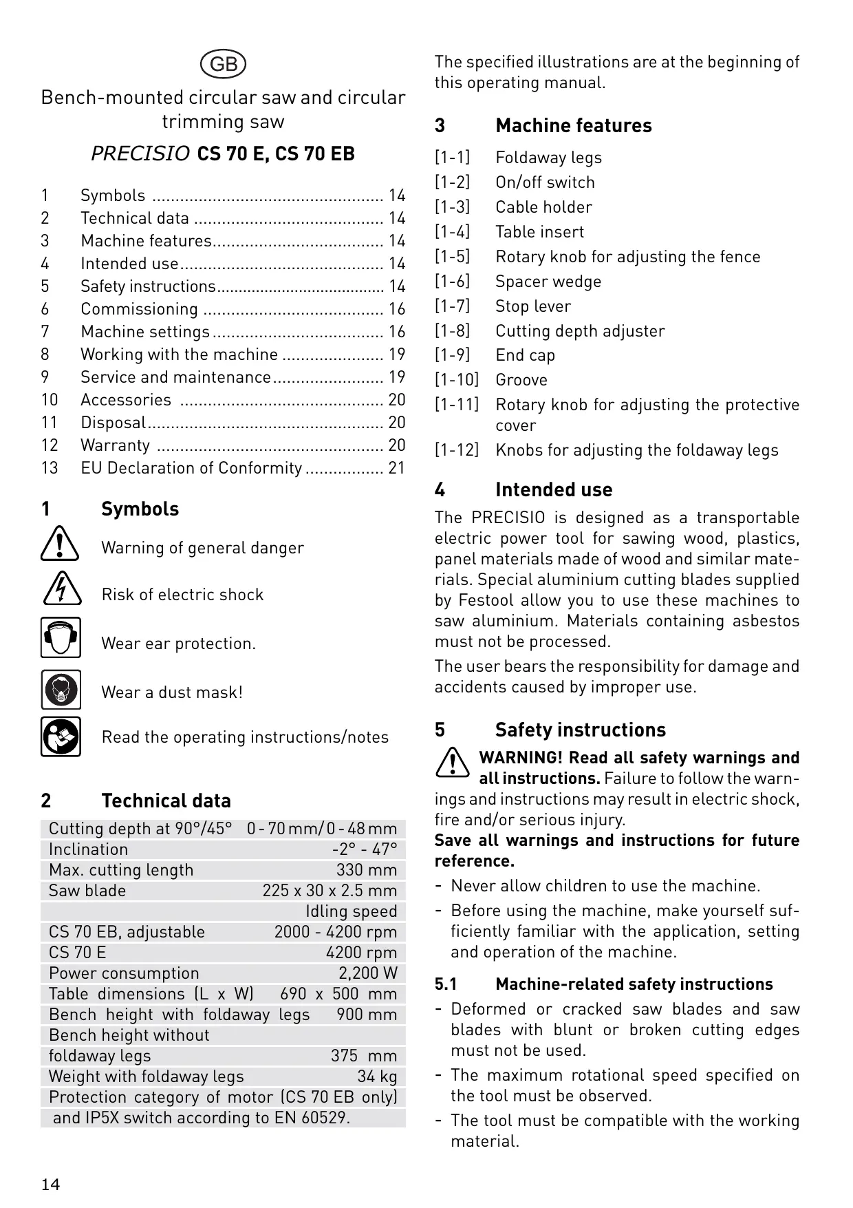
The specified illustrations are at the beginning of this operating manual.
3 Machine features
[1-1] Foldaway legs
[1-2] On/off switch
[1-3] Cable holder
[1-4] Table insert
[1-5] Rotary knob for adjusting the fence
[1-6] Spacer wedge
[1-7] Stop lever
[1-8] Cutting depth adjuster
[1-9] End cap
[1-10] Groove
[1-11] Rotary knob for adjusting the protective cover
[1-12] Knobs for adjusting the foldaway legs
4 Intended use
The PRECISIO is designed as a transportable electric power tool for sawing wood, plastics, panel materials made of wood and similar materials. Special aluminium cutting blades supplied by Festool allow you to use these machines to saw aluminium. Materials containing asbestos must not be processed.
The user bears the responsibility for damage and accidents caused by improper use.
5 Safety instructions
WARNING! Read all safety warnings and all instructions. Failure to follow the warnings and instructions may result in electric shock, fire and/or serious injury.
Save all warnings and instructions for future reference.
- Never allow children to use the machine.
- Before using the machine, make yourself sufficiently familiar with the application, setting and operation of the machine.
5.1 Machine-related safety instructions
- Deformed or cracked saw blades and saw blades with blunt or broken cutting edges must not be used.
- The maximum rotational speed specified on the tool must be observed.
-
The tool must be compatible with the working material.
-
Saw blades made of High Speed Steel (HSS steel) must not be used.
- Transport and store the tools in a suitable receptacle;
- Wear suitable personal protective equipment: ear protection to reduce the risk of hearing loss, safety goggles, a dust mask to prevent inhalation of harmful dust, protective gloves when working with raw materials and when changing tools.
- Only use tools that meet standard EN 847-1.
- Pull the plug from the main power socket before changing tools and rectifying faults such as removing trapped splinters.
- When cutting wood, connect the machine to a dust extractor corresponding to EN 60335-2-69, dust category M.
- To minimise noise, the tool must be sharpened and all noise reducing elements (covers etc.) must be properly adjusted.
- Only use the machine if all safety devices are in their correct positions, the machine is in good condition and has been well maintained.
- Faults on the machine, including the separating guards or the tool, must be reported to maintenance staff immediately upon discovery. The machine must not be used until the fault has been eliminated.
- Cutting rebates or grooves is only permitted with a suitable protective device fitted, e.g. a protective tunnel over the saw table.
- Do not use circular saws for cutting slots (grooves in workpiece).
- Do not use the top protective cover as a handle for transportation!
- Before transporting the machine, make sure that the top protective guard covers the top section of the saw blade.
- Use a suitable device to support long workpieces and ensure that they are horizontal.
- Make sure that there is adequate lighting in the room or workplace.
- Operating personnel must have received adequate training in the use, set-up and operation of the machine.
-
Always assume the correct position before starting work:
-
front at the operating end,
-facing the machine, -
next to the cutting line.
-
Never process material containing asbestos.
- Do not remove offcuts or other workpiece parts from the cutting area while the tool is still running and until the saw blade stops.
- If the saw blade is blocked, switch the machine off immediately and disconnect the mains plug. Do not remove the jammed workpiece until you have done this.
5.2 Emission levels
Noise emissions have been measured in accordance with the specifications in EN 61029. These specifications apply for operation as a trimming saw and bench-mounted circular saw.
Noise level
| Sound power level, idling | 91 dB(A) |
| Sound power level, during operation | 103 dB(A) |
| Measuring uncertainty allowance | K = 3 dB |
| Workplace emission levels | |
| Workplace emission, idling | 77 dB(A) |
| Workplace emission, during operation | 90 dB(A) |


CAUTION
The noise produced during work may damage your hearing.
Wear ear protection!
Measured acceleration < 2.5 ~m / s^2
The emission values specified (vibration, noise) were measured in accordance with the test conditions stipulated in EN 61029 and are intended for machine comparisons. They are also used for making preliminary estimates regarding vibration and noise loads during operation.
The emission values specified refer to the main applications for which the power tool is used. If the electric power tool is used for other applications, with other tools or is not maintained sufficiently prior to operation, however, the vibration and noise load may be higher when the tool is used. Take into account any machine idling times and downtimes to estimate these values more accurately for a specified time period. This may significantly reduce the load during the machine operating period.
5.3 Other risks
In spite of compliance with all relevant design regulations, dangers may still present themselves when the machine is operated, e.g.:
- workpiece parts being thrown off,
- parts of damaged tools being thrown off,
- noise emissions,
- wood dust emissions.
6 Commissioning

WARNING
Risk of accident if the machine is operated using unauthorized voltages or frequencies.
The mains voltage and the frequency of the power source must correspond with the specifications on the machine's name plate.
In North America, only Festool machines with voltage specifications of 120 ~V may be used.
6.1 Assembling the machine
Setting up the machine
Ensure that the floor around the machine is level, in good condition and free of loose objects (e.g. chips and offcuts).
① The machine can be set up with or without the legs unfolded. To unfold the legs:
Unscrew the rotary knobs [1-12] all the way.
Unfold the legs [1-1] and tighten the rotary knobs [1-12] again.
If the machine wobbles, turn the end cap [1-9] on one leg to adjust the length so that the machine stands securely.
Fitting the knob
Screw the rotary knob [2-6] supplied anticlockwise into the guide rod.
Fitting the protective cover
- Pull the spacer wedge [1-6] sharply upwards [7-2] to move to the top catch position.
- Secure the top protective cover supplied to the spacer wedge in this position using the rotary knob [1-11].
Transport
Engage the saw unit in the zero position.
- Remove all attachments from your saw and wind up the cable on the cable holder.
Fold up the legs.
6.2 On/Off switch
We recommend using a 16 A fuse because of the performance of the motor.
To switch on: Press the green "On" switch [1-2]. The red button is the "Off" switch.
A switch-on lock is available as an accessory to prevent the machine from switching on unintentionally.
7 Machine settings

WARNING
Risk of accident, electric shock
Always pull the plug out of the socket before performing any type of work on the machine.
7.1 Electronics
The machine features full-wave electronics with the following properties:
Smooth start-up
The electronically controlled smooth start-up function ensures that the machine starts up smoothly.
Speed control
You can regulate the rotational speed (CS 70 EB only) steplessly between 2000 and 4200 rpm using the adjusting wheel [2-1]. This enables you to optimise the cutting speed to suit the respective material.
The preselected motor speed remains constant through electronic control. This ensures a uniform cutting speed even when under strain.
Overload safety device
The machine power supply is limited if the machine is overloaded to extremes. The power supply is interrupted permanently if the motor is blocked for a few moments. Switch the machine off and on again to reset.
Temperature cut-out
The machine power supply is limited and the speed reduced if the motor exceeds a certain temperature. The machine continues operating at reduced power to allow the ventilator to cool the motor quickly. The machine starts up again automatically once the motor has cooled sufficiently.
Brake (CS 70 EB only)
After the machine switches off, the saw blade is electronically brought to a standstill in 3 seconds.
Restart protection
The integral undervoltage release prevents the machine from automatically starting up again after an interruption in power when the machine is used in continuous operating mode.
The machine will have to be switched back on in this case.
7.2 Set-up position
Always move the saw to set-up position before making any adjustments:
The saw is locked in rest position on delivery.
Turn the rotary knob [2-6] anticlockwise to release the lock and pull the saw forwards.
Push the stop lever [1-7].
The saw is locked in the front position.
7.3 Adjusting the cutting depth
Proceed as follows to adjust the cutting depth in set-up position to any setting between 0 - 70 mm:
Turn the cutting depth adjuster [1-8].
① Set a cutting depth 2 - 5 mm greater than the thickness of the workpiece to produce a clean cut.
7.4 Adjusting the litre angle
The saw blade can be tilted between 0^ and 45^ in set-up position:
Unscrew the rotary knob [2-4].
- Adjust the litre angle using the rotary handle [2-3] with reference to the scale [2-5].
Tighten the rotary knob [2-4].
The saw blade can be tilted 2^ beyond the two end positions for precision trimming work (undercuts on abutting edges).
Press and hold the button [2-2] in the end position.
The saw blade can now be tilted from -2^ to 47^ using the rotary handle [2-3]. Release the button [2-2] to reactivate the 0^ and 45^ stops.
7.5 Changing tools
Removing saw blades
Lock the saw in set-up position.
- Set the widest inclination angle and the maximum cutting depth.
- Loosen the clamp on the insert via the rotary knob [5-1].
▶ Slide the clamping plate forwards.
- Reach underneath the table insert [1-4] from the back and remove by lifting away from the back of the table.
Remove the protective cover.
Swivel the cover [5-10] backwards. - Remove the hexagon wrench [5-3] from the store on the base [5-6] and insert in the saw blade retaining screw.
Press and hold the spindle stop [5-2] (behind the saw blade) and use the hexagon wrench to turn the saw shaft until the spindle stop [5-2] engages and the saw shaft locks.
① The saw blade retaining screw has a left-handed thread.
Firmly turn the saw blade retaining screw clockwise and remove the clamping flange and the saw blade.
Installing saw blades

WARNING
Risk of injury
Observe the rotation direction when attaching a new saw blade: the rotation direction on the saw blade [5-4] must correspond with the rotation direction on the machine.
Place the saw blade in position.
- Secure the saw blade and the flange to the saw shaft using the saw blade retaining screw.
- Close the cover [5-10] and fit the protective cover.
- Make sure that the cover [5-10] engages in the tabs [5-9].
Replace the hexagon wrench [5-3] back in the store.
Fitting the table insert [1-4] in the table
Insert the protruding spring plate [5-5] on the insert forwards into the table frame first. Make sure that the contact surface is free of dust.
Lay the insert in position and secure with the clamp and the rotary knob [5-1].
7.6 Setting the spacer wedge
Once the protective cover is removed, pull firmly on the spacer wedge [1-6] to move to one of two catch positions. The spacer wedge is used in the top catch position [7-2] in the all applications, except concealed cuts.
For concealed cuts only
Remove the top protective cover.
Press down the spacer wedge firmly to move to the lower catch position [7-1].
When producing concealed cuts, make sure you guide the machine accurately. Press the workpiece firmly onto the table. When cutting the workpiece, make sure that the side of the workpiece that is already cut out is not on the same side as the fence.
After completing concealed cuts, move the spacer wedge [1-6] back to the top position and attach the protective cover (see chapter 6.1).
7.7 Fence
The fence can be attached at any point along the clamping edge of the saw base and is so versatile, it can be used as a cross stop [Fig. 1] or a longitudinal stop [Fig. 6].
① Before attaching, make sure that the contact surfaces of the fence are not dirty.

WARNING
Risk of injury
Always use the fence in a fixed position and do not use to slide the workpiece along!
Fitting the fence
Open the clamping jaws using the knob [4-4].
Place the fence with guide rail [4-5] onto the clamp rail from above.
- Secure the clamp segment using the knob [4- 4].
The fence can be adjusted in the following ways:
Move the fence on the clamp segment
- Unscrew the rotary knob [1-5] and move the fence.
Move the stop ruler
Unscrew the rotary knob [4-1] and move the fence.
The stop ruler is stepped on one side by 8 mm. This guide rail can be used to guide the cross stop up to the saw cut to support the workpiece without having to remove the top protective cover.
Adjust the angle
- Unscrew the rotary knob [4-2] and lift the retaining pin [4-3].
The rotary retaining pin engages at the most frequently used angle settings.
Adjust the position of the stop profile
Unscrew the rotary knob [4-1].
Remove the guide rail [4-6] and turn 90^
Place the guide rail in the guide slot available. [Fig. 4]
The dimensions of the aluminium profile provide a high guide surface for high workpieces and a low guide surface for flat workpieces.
Longitudinal stop
Position the stop ruler parallel to the blade to make rip cuts.
- Use the workpiece holder [6-1] for guiding narrow workpieces.
The two rulers on the left and right of the saw blade cutting edges [7- 1] are set to zero ex works so that the fence can be aligned with the scale along the front edge of the table.
7.8 Fitting the splinterguard
NOTE
The splinterguard cannot be used when making bevel cuts. Remove the splinterguard as necessary.
Unscrew the rotary knob [5-1].
▶ Slide the clamping plate forwards.
- Lift the table insert [1-4] from the rear end and remove.
Set the saw blade to the minimum cutting depth.
▶ Slide the splinterguard [8-3] up to the side of the retainer [8-1].
- Place the table insert [1-4] in position and tighten the rotary knob [5-1].
Switch on the machine and move the saw blade slowly upwards to the maximum cutting depth.
This beds in the splinterguard. The raised section [8-4] of the splinterguard should protrude slightly (approx. 0.3 mm ) over the edge of the table so that the splinterguard functions more effectively.
- Unscrew both screws [8-2] to adjust the height of the retainer [8-1].
7.9 Dust extraction

CAUTION
Breathing in dust can damage the respiratory passage!
Always connect the machine to a dust extractor.
- When performing work that generates dust, always wear a dust mask.
The PRECISIO has two extraction connectors: top protective cover [3-7] 27 mm in diameter and the lower protective cover [3-3] 35 mm in diameter. Attach the hose holder [3-6] to the clamp rail on the saw base to guide the top suction hose.
The extractor set CS 70 AB [3-4] (included in CS 70 EB scope of delivery) joins both extraction connectors so that a Festool mobile dust extractor with 50 ~mm adapter can be connected.
8 Working with the machine

WARNING
Risk of injury
Always read all safety instructions when working with the machine!
- Never work with the machine in the front position (set-up position).
Make sure that all rotary knobs on the fence and the machine are tightened before starting work.
Adjust the top protective cover until it rests on the workpiece and secure in this position using the rotary knob [1-11].
8.1 Using the machine as a bench-mounted circular saw
When used in bench-mounted applications, the saw is fixed and the workpiece is moved.
Pull the saw forwards.
Allow the saw to glide back slowly.
You can push the stop lever [1-7] down after a few millimetres.
If the saw continues to glide back, the stop lever engages in the guide rod and secures the saw at the centre of the table (bench saw position).
Use the fence as a longitudinal stop [Fig. 6] to guide the workpiece.
Guide the workpiece by hand. Use the workpiece holder [6-1] to guide the workpiece accurately past the saw blade.
- Place the workpiece holder in the store [2-7] when not in use.
8.2 Using the machine as a trimming saw
When the machine is used for trimming work, the workpiece remains stationary and the saw is moved to make the cut.
- Turn the rotary knob [2-6] anticlockwise to release the saw lock.
Push down the stop lever [1- 7] to unlock and move the saw to the forward position so that the control elements are easy accessible when the saw settings are adjusted. Turn the rotary knob [2- 6] anticlockwise to release the lock again.
Attach the cross or angle stop [Fig. 1] so that the workpiece is retained securely on the saw base.
Alternatively, insert clamps (accessories) in the groove [1- 10] to secure the workpiece.
- Use the rotary knob [2-6] to draw the saw forwards and make the cut.
After completing the cut, move the saw unit right back to its starting position before removing the workpiece from the fence.
9 Service and maintenance

WARNING
Risk of accident, electric shock
Always pull the plug from the mains power supply before maintaining, servicing or making any kind of adjustment.
- All maintenance and repair work which requires the motor housing to be opened, must only be carried out by an authorised service workshop.
- Damaged safety devices and parts should be repaired or replaced by an authorised service centre unless otherwise specified in the operating instructions.
The machine is equipped with special self-disconnecting carbon brushes. If they are worn, the power is interrupted automatically and the machine comes to a standstill.
Maintain your machine regularly to make sure it functions reliably:
- Use an extractor to remove the dust deposits.
-
Keep the guide rods clean and grease regularly.
-
Keep the toothed gears behind the rotary handle [2-3] clean.
- Replace worn or damaged table inserts [1-4].
- If wood chips block up the extraction channel on the lower protective cover, unscrew the rotary knob [5-8] and move the flap [5-6] approx. 8mm to open up a gap so that the blockage is removed.
- If the blockage is serious or the saw seizes when the initial cut is made, unscrew the fasteners [5-7] using the hexagon wrench so that the flap [5-6] can be opened completely. Close the flap again prior to use.
- After completing work, wind up the power cable onto the holder [1-3].
- A damper allows the saw unit to retract evenly along the entire cutting length. If this is not the case, the damper can be adjusted through the hole [3-5].
Filter cleaning (CS 70 EB only)
You should clean the air intake filter [3-2] if the temperature monitor (see 7.1) triggers shutdown cycles more frequently without the machine being overloaded excessively.
Unscrew the rotary knob [3-1].
Remove the filter insert.
- Knock off the dust or use an extractor on the surface of the filter.
Insert the filter again.
If damaged, replace the filter with a new filter cartridge.
10 Accessories
Use only original Festool accessories and Festool consumable material intended for this machine because these components are designed specifically for the machine. Using accessories and consumable material from other suppliers will most likely affect the quality of your working results and limit any warranty claims. Machine wear or your own personal workload may increase depending on the application. Protect yourself and your machine, and preserve your warranty claims by always using original Festool accessories and Festool consumable material!
11 Disposal
Do not throw the power tool in your household waste! Dispose of machines, accessories and packaging at an environmentally-responsible recycling centre. Observe the valid national regulations.
EU only: European Directive 2002/96/EC stipulate that used electric power tools must be collected separately and disposed of at an environmentally responsible recycling centre.
12 Warranty
For our tools, we give warranty for material and production defects in accordance with the locally applicable legal provisions, but in any case for at least 12 months. Within the EU member states, the warranty period is 24 months (verification through invoice or delivery note). Damage caused by, in particular, natural wear, overloading, incorrect handling, or damage caused by the operator, or damage caused through use of the equipment contrary that specified in the Operating Instructions, or damage which was known at the time of purchase, is not covered by the warranty. Furthermore, damage caused by the use of non-original accessories and consumable materials (e.g. sanding pads) is also excluded.
Complaints can only be recognised if the tool is returned while still assembled to the supplier or an authorised Festool Customer Service workshop. Keep the Operating Instructions, Safety Instructions, Spare Parts List and purchase receipt in a safe place. Otherwise the respective, current warranty conditions of the manufacturer shall apply.
Note
Due to continuous research and development work, we reserve the right to make changes to the technical content of this documentation.
13 EU Declaration of Conformity
| Bench-mounted circular saw and circular trimming saw | Serial no. | |
| CS 70 E | 491304, 491305, 493474 | |
| CS 70 EB | 491302, 491303, 493559 | |
| Year of CE mark | 1995 | |
We declare under sole responsibility that this product complies with the following norms or normative documents:
EN 61029-1, EN 61029-2-1, EN 55014-1, EN 55014-2, EN 61000-3-2, EN 61000-3-3 in accordance with the regulations 2006/42/EC, 2004/108/EC.
paa. 0j. Jdaannnnn nn
Head of Research, Development and Technical
Documentation

Festool GmbH
Wertstrasse 20,
D-73240 Wendlingen
REACH for Festool products, their accessories and consumables
REACH is a European Chemical Directive that came into effect in 2007. As “downstream users” and product manufacturers, we are aware of our duty to provide our customers with information. We have set up the following website to keep you updated with all the latest news and provide you with information on all the materials used in our existing products: www.festool.com/reach
F
Varning for allman risk!

Varning for elstötar

Använd hörskyydd!

Saven lases derved i forreste position.
UpoBHeB MoIuHocTn 3ByKOBbIX KoJe6aHn
| Уровenvь 3ВУКОВМошноCTN НахолочTomхов | 91 ДБ(A) |
| Уровenvь 3ВУКОВМошноCTN ри образOTKE | 103 ДБ(A) |
| Доручь на погешиноCTB | |
| Измерени | К = 3 ДБ |
UpoBnI yMaHa pa6ooyem MeCTe
MoHTaX BnHToBovpyuKn
BpaueHnem BJIeBO 3aBepHnTe BXoJusn B KOMPJIeKT NocTaBKn BuHT-6apaWeK [2-6] B UHTAHrpy npOTJxKn.
Mоntаж ЗашитHorо кожуха
Пиведи te pa3ЖИМной Клин [1-6] моцьIM DBижehнem BВepx [7-2] В БерхqueeфнксюBaHHoe NOLOXeHne.
B 3tOM pIoJoxeHn npNBepHnte BxoJaIuN B KOMJIeKT nOCTaBKn BepXHn 3aUHTbI K0-JKyx K pa3xHMHomy KJIHy npN POMoU N BuHTa-6apawka [1-11].
TpaHcnpTnpoBka
3aΦκκργιTe Πηλγ B HυλeBOM ΦολοχεΗΝΙ.
Chmnte Bcê Habechoe o6opydoBaHne, ycta-HOBJIeHHoe Ha nIne, n HAmOtaiTe Ka6eIb Ha cNeuaJIbHOe KpeJIeHne.
CLOXKTe HOXKN.
6.2 BkJIoueHne/ByIKJIoueHne
13-3a BbICOKo MOUHOCn DBNrATeJIpeKOMeHdyETcYCTaHOBnTb PpeOxpaHnTeJIb Ha 16 A.
ДляВКЛIOUeHЯ:нжмITEHa3eJIeHbI Bbl- KJIIOuATEJIb[1-2].KpacnaKHOJkaNcNoJIb3y-etcraДлЯВыКЛIOUeHЯ.
①Для 3auntbI OT He npedHaMepeHnHO BKIO-ueHnB KaueCTBe OChactKN ppeJaaraTcra 3aInpaUoosci6bloknpaTop BKIOuOeHnA.
7 PeruginpoBka 3JeKtpoHCTpymeHTa

ПЕДУПЕЖДЕНЕ
Onachoctb HeccaCTHOro clyua, ydapa TokOM
YCTaHOBka NJIbHOrO DnCKa

ПЕДУПЕЖДЕНЕ
Onachoctb TpaBMnpoBaHna
Пи установке HOBOTo ПИльно Г ДИСКа се-дпTe 3a соблюденем наразвлени Врашени: наразвлени Врашени ПИльно Г ДИСКa [5-4]doJxHo coBпадаьс наразвленим Эльктуоннструментa.
BnOxHTe nIbHbI dNcK.
PnBepHnTe nIbHbI NcK n ΦlaHeu coeHNHTeJIbHbIM 6oITOM nIbHOrO dNcKa K ycta-HOBKe npNbOda nnbl.
3aKpoIte kOxUx [5-10] uYcTaHOBuTe 3aunT-NbI KoxUx.
YIOCTOBeBbTeCb B TOM, TTo KOJyX [5-10] npn 3aKpbITnN nOpaJaT B npope3n [5-9].
BcTaBbTe 8eCTnIgpaHbI pOxKOBbl KInOu [5-3] o6paTHo B dePkaTeJIb.
ToIbko IJIa EC: corglaacHo EbponeeCKoI n-
pekTbe 2002/96/EG oTcnyKbIe cBoi cpoK 3JIeKTpOHNCTpyMeHTbI DOJXHbI yTNJIN3nPoBA TbCBs OTeJIbHO nHa npaBJIaTBcR Ha 3KOJIoRnHyU yTNJIN3aCNIHO.
12 TapaHTnA
Ha haui HNCTpymEnMbI Daem rapaHTnIO,pacnpocTpaHJUOyUcH Ha MaTePnaJIbI N DeΦeKtBI N3rTOBJIeHNBA COOTBeTCTBUN C 3aKOHOdaTeJIbCTBOM KaJdoi n3 cTpaH, Ho He Mehbe 12 MecaueB.B cTpaHax EC cpoK rapaHTn coCTabJIeT 24 MecaZu (noTBePjXdHne No CteTy IIN HaKlaJHO). TapaHTnHe paCnpocTpaHJeTcH Ha NOBpeXJdeHN, POJUeHHbE B pe3yJIbTaTe ECTeCTBeHHORo U3HOca/ncNoJIb3OBaHn, NepeRpy3Kn, NcNoJIb3OBaHn He No Ha3NaeHNIO, NOBpeXJdeHN IO BInHe noJIb3OBaTeJIaI INI Prn 3KcJIyaTaUcN BOJpeKN pyKOBODCTBy NO 3KcJIyaTaUcN, IIN60 I3-BeCTHbIE Ha MOMENT NOKyIKN (yuENKa TOBAPA). TaKxe NcKJIouaETcY OTBeTCTBeHHOCTB 3a yUep6, Bbl3BaHHbI NcNoJIb3OBaHnEM HeOpnIHaNBJHO OCHACTKN i pacxOJNbIX MaTePnaJIoB (Ha npImep, UInΦOBaJIbHbIX TapeJOK).
PeKlamau npHnMaOTcK paCCMOtpeHIO TToIbKO B TOM clyuae, eCIn nHCTpyMeHT NOCTyNII K NoCTaBUnky NIN B aTTecTOBaHHyU MaCTepCKyIO CepBnCHo CJyX6bl Festool B Hepa3O6paHHom BVide. CoxpanYe pykoBOdCTBO no 3KcNpyaTauN, yKa3aHnI PO Texnke 6e3OpacHOCTn, cnCOK 3aPacHbIX qAcTeN I KBtAnCuI O nOkynke. B OCTaJIbHOM IMeOT cNly DeiCTByIOUne Ha onpeDeJeHNbI MOpENT UcNoBnI PpeIoCTaBJIeHnIraPaHTNI IN3rOToBnTeJEM.
PpimmeaHne
B CB83n C NOCTO8HHbIMN HCCJIeIOBaHn8MNI HOBbIMN TexHnueCKmN pa3pa60TKamN φnpMa OCTaBJIa8ET 3a CO6oI npaBO Ha BHeceHne I3MeHHeH N B TexHnueCKne XapaKTePncTnKn.