
WLAN ROUT 54-N - WLAN Router VIVANCO - Free user manual and instructions
Find the device manual for free WLAN ROUT 54-N VIVANCO in PDF.
| Product type | WLAN Router |
| Brand | VIVANCO |
| Model | WLAN ROUT 54-N |
| Network standards | IEEE 802.11b/g, IEEE 802.3/3u (10/100BASE-TX) |
| Maximum wireless speed | 54 Mbps (turbo 72 Mbps) |
| Number of LAN ports | 4 Fast Ethernet 10/100 RJ-45 ports |
| WAN port | 1 Ethernet 10/100 RJ-45 port |
| Antenna | Detachable, reverse SMA connector |
| Wireless security | WEP 64/128 bits, WPA (TKIP), WPA2, AES |
| Firewall features | SPI, Anti-DoS, DMZ, IP/MAC/URL/Port filtering |
| Supported WAN protocols | PPPoE, PPTP, DHCP client, Static IP |
| Built-in DHCP server | Yes |
| Memory | Flash 2 MB (NOR), SDRAM 8 MB |
| Power supply | External adapter 12 V DC, 1 A |
| Operating temperature | 0 °C to 40 °C |
| Operating humidity | 10 % to 90 % |
| RF transmit power | 16 to 18 dBm |
| Indoor range | 35 to 100 meters |
| Outdoor range | 100 to 300 meters |
| Certifications | FCC Class B, CE, VCCI Class B |
| Care and cleaning | Clean with a soft dry cloth. Do not use liquid or abrasive products. |
| General information | 802.11b/g WLAN router with integrated access point, Internet connection sharing (NAT), web configuration interface. |
Frequently Asked Questions - WLAN ROUT 54-N VIVANCO
User questions about WLAN ROUT 54-N VIVANCO
0 question about this device. Answer the ones you know or ask your own.
Ask a new question about this device
Download the instructions for your WLAN Router in PDF format for free! Find your manual WLAN ROUT 54-N - VIVANCO and take your electronic device back in hand. On this page are published all the documents necessary for the use of your device. WLAN ROUT 54-N by VIVANCO.
USER MANUAL WLAN ROUT 54-N VIVANCO
WLAN ROUTER 802.11g , 54 Mbit/s
User's Guide
Bedienungsanleitung
Notice d'emploi
This equipment complies with the requirements relating to electromagnetic compatibility, EN 55022 class B for ITE, the essential protection requirement of Council Directive 89/336/EEC on the approximation of the laws of the Member States relating to electromagnetic compatibility.
Company has an on-going policy of upgrading its products and it may be possible that information in this document is not up-to-date. Please check with your local distributors for the latest information. No part of this document can be copied or reproduced in any form without written consent from the company.
Trademarks:
All trade names and trademarks are the properties of their respective companies. Copyright © 2007, All Rights Reserved.
23414
WLAN ROUT 54-N
GB
UNPACKING INFORMATION
Thank you for purchasing the product. Before you start, please check all the contents of this package.
The product package should include the following:
- One Wireless Router
- One power adapter
- One User Manual (CD)
- One detachable antenna
INTRODUCTION TO WIRELESS ROUTER
General Description
The Wireless Router built-in with 4-port 10/100Mbps Fast Ethernet Switch is the latest generation of Wireless router product for Home/Office and SOHO users. This full-feature and self-contained compact Wireless Router will be fully for broadband access in both of LAN and Wireless environment. This device has been specifically designed to provide LAN and Wireless users the most cost-effective method with multiple accesses to the Internet at the cost of a single public IP address (IP Sharing) and enjoy the true Plug-and-Play installation. Moreover, the built-in 4-port 10/100Mbps switch lets users plug the network cable into the device without buying additional switch.
This device is also an Access Point. It has a built-in wireless LAN. Users can connect to Internet using wireless network interfaces anywhere within the range of its radio transmission. It's ideal for SOHO users who require instant and convenient access to Internet without the restriction of connecting cables.
The friendly WEB-based graphics interface for setup makes any inexperienced users soon enter plug-and-play operation. Embedded DHCP server simplified IP address management and no MIS people needed for daily technical services. What is more, NAT/firewall is also implemented on this compact Router Box for protecting whole LAN from outside attack.
23414
WLAN ROUT 54-N
Key Features
The switch provides the following key features:
Complies with IEEE 802.11b/g wireless standards
■ Provides one 802.11b/g wireless Reverse SMA detachable antenna
High speed transfer data rate up to 54Mbps
Supports turbo mode for 72Mbps data transfer
Supports wireless data encryption with 64/128-bit WEP, WPA (TKIP with IEEE 802.1x), WPA2 and AES functions
Supports system log
Supports authentication for wireless connectivity based on ESSID
Provides MAC access control and hidden SSID function
WDS supported with WEP, TKIP and AES encryption
Channel: USA 11, Europe 13, Japan 14
Supports NAT/NAPT IP Sharing
Supports Static IP, PPPoE, PPTP, & DHCP client
SPI Anti-DoS Firewall; Virtual DMZ; DNS relay; UPnP
Provides DHCP server
Supports ALG for FTP, NetMeeting, DDNS (DynDNS, TZO)
Supports firmware upgrade function via Web
Compliant with FCC Part 15.247 for US, ETS 300 328 for Europe
■ Flash: 2MB NOR type, SDRAM: 8MB
Certifications: FCC Class B, CE Mark, VCCI Class B
23414
WLAN ROUT 54-N
The Front Panel

LED definition
System LEDs
System LED indicators locate on the front panel for showing the operating status of the whole device.
PWR (Power) LED
This indicator lights green when the Wireless Router is receiving power; otherwise, it is off.
- Status LED
The LED will be dark for a few seconds when the system is started. After that, the LED will blink periodically to show the Wireless Router is working normally. If the LED stays green/dark that means the system failed, you need to contact your agent or try to reboot the system.
Port LEDs (Wireless)
WLANLED
I. When system is ready for data transmitting and receiving, it is steady green.
II. When the data is transmitting or receiving, it is blinking green.
23414
WLAN ROUT 54-N
Port LEDs (WAN)
Port LED (WAN) indicators locate on the front panel for showing the operating status of WAN port.
- Act/Link LED
The LED stays light (green) means the port has good linkage to its associated devices.
The LED will blink green when there is traffic transverse the port.
Port LEDs (LAN)
Port LEDs (LAN) indicators locate on the front panel for showing the operating status of 10/100Mbps Fast Ethernet switching ports.
- Act/Link LED
Every port has a Act/Link LED. Steady green (link state) indicates that the port has good linkage to its associated devices. Flashing green indicates that the port is receiving or transmitting data between its associated devices.
The Rear Panel
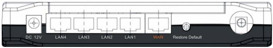
Power Connection
Plug the circle end of the power adapter firmly into the rear panel of the Wireless Router, and the other end put into an electric service outlet then the system is ready.
Placement (Optional)
There are three ways to place the Router. The first way is to place the Router horizontally on a surface. The second way is to attach the router to the wall. The third way is to stand the Router vertically on a surface. These options are explained in further detail below.
23414
WLAN ROUT 54-N
Desktop Option
- The Router has one plastic stand that can be divided into two parts.
- Combine one part of stand with the side of router.
- Do the same with the second part.
- Place the Router
Wall-mount option
Before attach this router on the wall, you have to finish the desktop option steps first.
- Select a location with access for cables and a power outlet.
- Unplug the unit. Place it upside down on a flat surface and mark the two holes for anchors.
- Installing the Wall mount anchor (plastic) into the wall with tools such as drill or hammer.
- Insert the provided screws in each hole of the stand parts.
- Attaches the unit to the anchors on the wall.
Stand Option
- The Router includes two stand parts.
- Combine two parts into one stand. Combine it with the side of router near the power port. Push the stand up to snap it into place.
- Place the Router.
- Push the button for more than 5 seconds and then release it, the system will return to factory default setting. In the meantime, system rewrites flash to default value and Status LED halts for a while. Approximately 60 seconds later, the Status LED blinks green periodically, now the whole system parameters have returned to factory default value. If the process has been interrupted by any reason (power off...), the system will fail. Before performing the process, ensure a safe operating environment please.
- To reboot the Router, Press the button for 2-5 seconds and then release it, and all the setting won't be erased. Wait for the Router to complete the reboot, and then you can start to use it.
Warning! Incomplete factory setting recovery procedure will cause the Wireless Router malfunction. If you are unfortunately in this situation, do not try to repair it by yourself. Consult your local distributor for help.
INSTALLING AND USING WIRELESS ROUTER
This Chapter provides a step-by-step guide to the installation and configuration of the Wireless Router. We suggest you go over the whole chapter and then do more advanced operation.
Network configuration setup
Steps to build up the network:
Connect the ADSL or Cable modem to the Ethernet WAN port on the back of the Wireless Router by using the UTP cable.
Connect the phone line from the wall socket to the line-in port on the ADSL modem, or the coaxial cable to the line-in port on the Cable modem.
Plug-in the power adapter to the modem and turn on the power. Install the Ethernet card into the computer by referring to the User Guide that came with the card.
Connect the computer to the Wireless Router by using standard twisted-pair Ethernet cable from the computer's Ethernet card to an 10/100Mbps Ethernet port on the back of the Wireless Router.
Plug-in the power adapter to the Router and the other side to the wall outlet.
23414
WLAN ROUT 54-N
Computer configuration setup
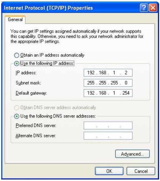
In order to communicate with this Wireless Router, you have to configure the IP addresses of your computer to be compatible with the device. The router supports DHCP server and it is enabled as default. Users that configure your IP address as "Obtain an IP address automatically" may skip the following IP configuration instruction.
Note:
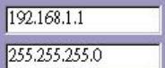
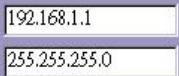
- The default network setting of the device:
IP address: 192.168.1.1
Subnet Mask:255.255.255.0
DHCP Server: enabled
- In the following TCP/IP configuration guide, the IP address "192.168.1.2" is assumed to be your IP address if you want to specify IP addresses manually. Please DO NOT choose 192.168.1.1 for the IP address (192.168.1.1) has been set as the default IP for this device.
- The following TCP/IP configuration guide uses windows XP as the presumed operation system.
Procedures to configure IP addresses for your computer
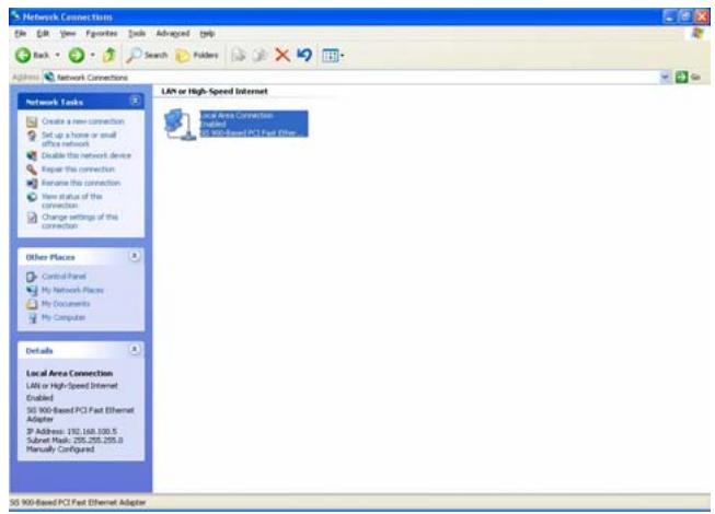
- If you are in Classic Start menu view, click Start > Settings > Control Panel > Network Connections.
- If you are in Start menu view, click Start > Control Panel > Network Connections.
- Double click "Local Area Connection"
23414
WLAN ROUT 54-N
- Choose Internet Protocol (TCP/IP) and click Properties.
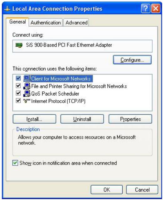
- You may choose "Obtain an IP address automatically"(recommend) to get IP address automatically or choose "Use the following IP address" to specify IP addresses manually. Please click the OK button after your configuration.
MANAGEMENT
Wireless Router configuration setup
In order to make the whole network operate successfully, it is necessary to configure the Wireless Router through your computer has a WEB browser installed. Please follow up the steps listed below.
- Double click the Internet WEB browser icon on your desktop screen (Netscape Communicator 4.0 and Internet Explorer 3.0 or update version)
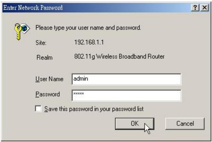
- Type 192.168.1.1 into the URL WEB address location and press Enter.

-
TheUsername and Password Required window appears.
-
Enter admin in the User Name location (default value).
- Enter admin in the Password location (default value).
- Click "OK" button
23414
WLAN ROUT 54-N
4. The Graphic User Interface
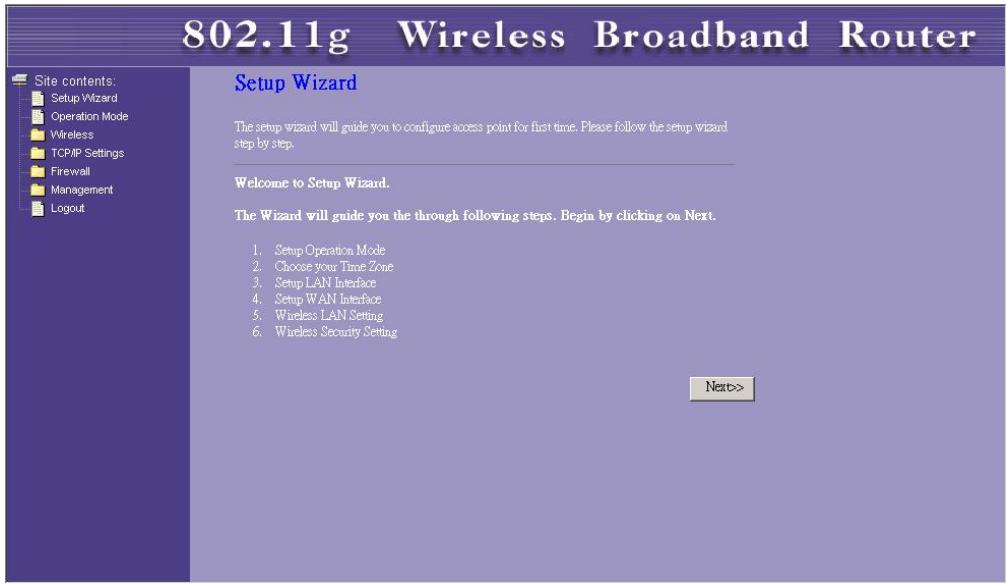
After the password authorization, the Setup Wizard shows up as the home page of the Graphic User interface. You may click on each folder on left column of each page to get access to each configuration page.
Setup Wizard
If you are using the router for the first time, you may follow the procedures of the setup wizard to do a step-by-step configuration.
Note: The following instruction does an overall introduction to the Setup Wizard. For detail information to each item, please refer to instruction of each page.
- To start the Setup Wizard, click the "Next" button to proceed.
Setup Wizard
The setup wizard will guide you to configure access point for first time. Please follow the setup wizard step by step.
Welcome to Setup Wizard.
The Wizard will guide you the through following steps. Begin by clicking on Next.
- Setup Operation Mode
- Choose your Time Zone
- Setup LAN Interface
- Setup WAN Interface
- Wireless LAN Setting
- Wireless Security Setting

- Select your demanding operation mode and click "Next".
1. Operation Mode
You can setup different modes to LAN and WLAN interface for NAT and bridging function.

In this mode, the device is supposed to connect to internet via ADSLCable Modem. The NAT is enabled and PCs in four LAN ports share the same IP to ISP through WAN port. The connection type can be setup in WAN page by using PPPOE, DHCP client, PPTP client or static IP.

In this mode, all ethernet ports and wireless interface are bridged together and NAT function is disabled. All the WAN related function and firewall are not supported.
Cancel
<Back
Next>
1

23414
WLAN ROUT 54-N
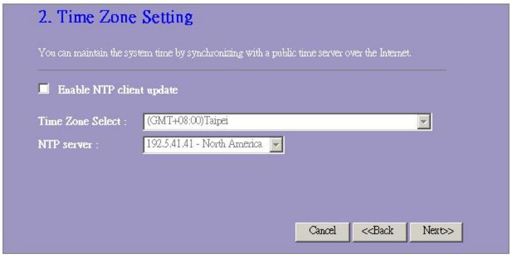
- Mark the check box to enable synchronizing time by NTP server. Select the religion you live and a NTP server by clicking the drop list then click "Next".
- Specify an IP address and subnet mask for connecting to the router in LAN.
23414
WLAN ROUT 54-N
- Select a WAN access type for the router to connect to Internet. Fill in the parameters that required in each blank, and then click the "Next" button. You may get those parameters from your ISP.
4. WAN Interface Setup
This page is used to configure the parameters for Internet network which connects to the WAN port of your Access Point. Here you may change the access method to static IP, DHCP, PPPoE or PPTP by click the item value of WAN Access type.
WAN Access Type:
IP Address:
Subnet Mask:
Default Gateway:
DNS:

- Select the wireless parameters that are used for associating with this router and click Next.
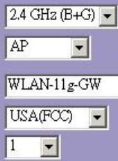
5. Wireless Basic Settings
This page is used to configure the parameters for wireless LAN clients which may connect to your Access Point.
Band:
Mode:
SSID:
Country:
Channel Number:

23414
WLAN ROUT 54-N
- Click the drop list to select the encryption type for your wireless network. Fill in the parameters for the encryption type you select and click finish to complete configuration.
6. Wireless Security Setup
This page allows you setup the wireless security. Turn on WEP or WPA by using Encryption Keys could prevent any unauthorized access to your wireless network.
Encryption: None
Cancel
Back
Finished
Operation Mode
To select an operation mode for this router, click on the mode that you want to perform and click
the Apply Change button to execute.
Operation Mode
You can setup different modes to LAN and WLAN interface for NAT and bridging function.
Gateway:
In this mode, the device is supposed to connect to internet via ADSL Cable Modem. The NAT is enabled and PCs in LAN ports share the same IP to ISP through WAN port. The connection type can be setup in WAN page by using PPPOE, DHCP client, PPPT client or static IP.
Bridge:
In this mode, all ethernet ports and wireless interface are bridged together and NAT function is disabled. All the WAN related function and firewall are not supported.
Apply Change
Reset
Wireless
Wireless Access Point builds a wireless LAN and can let all PCs equipped with
IEEE802.11b/g wireless network adaptor connect to your Intranet. It supports WEP encryption and MAC address filter to enhance the security of your wireless network.
Basic Settings
You can set up the configuration of your Wireless and monitor the Wireless Clients associate with your AP.
Configuration
| Disable Wireless LAN Interface Band | To Disable interface of Wireless LAN |
| To select a band for this device to match 802.11b, 802.11g or both. | |
| Mode | Configure this device as AP, WDS or both. |
| SSID | The name of the wireless network |
| Country | Select the region you live. |
| Channel Number | The channel used by the wireless LAN. All devices in the same wireless LAN should use the same channel. |
| Associated Clients | Click "Show Active Clients" button, then an "Active Wireless Client Table" will pop up. You can see the status of all active wireless stations that are connecting to the access point. |
| Enable Universal Repeater Mode | Mark this checkbox to enable Universal Repeater Mode which acts this device as an AP and client simultaneously. |
| SSID of Extended Interface | While you enable the Universal Repeater Mode, you have to specify anSSID for the extended interface. |
Click
You can now configure other advance sections or start using the router (with the advance settings in place)
Active Wireless Client Table
This is the window that pops up after clicking the "Show Active Clients" button.
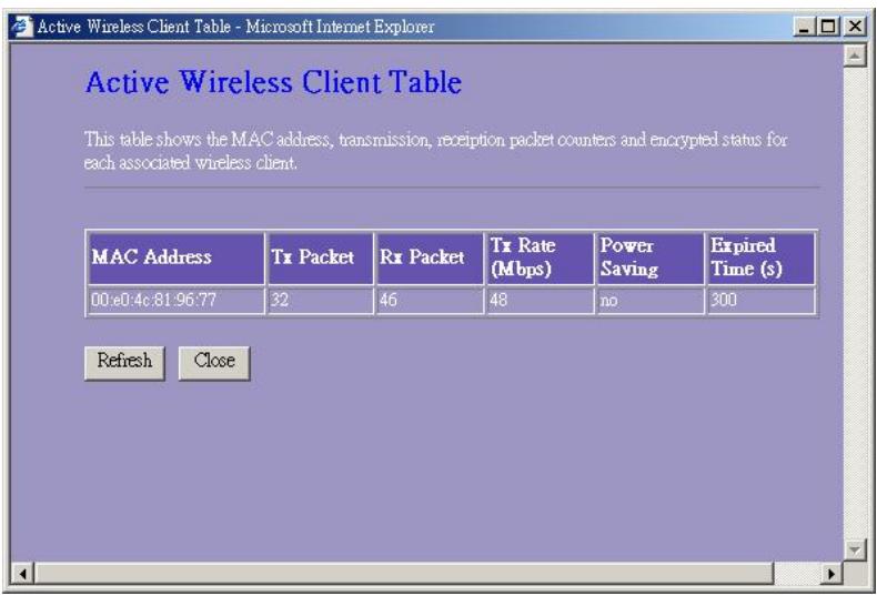
| MAC Address | MAC address of this active wireless station. |
| Tx Packet | The number of transmitted packets that are sent out from this active wireless station. |
| Rx Packet | The number of received packets that are received by this active wireless station. |
| TX Rate | The transmission rate |
| Power Saving | Shows if the wireless client is in Power Saving mode |
| Expired Time | This is the time in second before dissociation. If the wireless keeps idle longer than the expired time, this wireless router will dissociate it. The wireless client station has to associate again when it is active. |
| Refresh | Refresh the "Active Wireless Client Table". |
| Close | Close the "Active Wireless Client Table". |
Advanced Settings
You can set advanced wireless LAN parameters of this router. The parameters include Authentication Type, Fragment Threshold, RTS Threshold, Beacon Interval, Data Rate, Preamble Type, Broadcast SSID, IAPP and 802.11g Protection. We recommend not changing these parameters unless you know what changes will be there on this router.
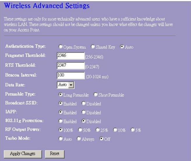
Wireless Advanced Settings
These settings are only for more technically advanced users who have a sufficient knowledge about wireless LAN. These settings should not be changed unless you know what effect the changes will have on your Access Point.
Authentication Type:
Fragment Threshold:
RTS Threshold:
Beacon Interval:
Data Rate:
Preamble Type:
Broadcast SSID:
IAPP:
802.11g Protection
RF Output Power.
Turbo Mode:

Open System

Shared Key

5

5-2346

7

。

0
1/2 =

Long Preamble

Short Preamble

Enabled.
isabled

Enabled.
D

∴ m = 3/11

Enabled

∴ m = 3/11 ;


100%
50

C

C

落

特

Auto
AI

6

m

∴ m = 3/11
Configuration
| Authentication Type | Open System mode | Wireless AP can associate with this wireless router without WEP encryption. |
| Shared Key mode | You should also setup WEP key in the "Security" page and wireless AP associating with this wireless router should use WEP encryption in the authentication phase. | |
| Auto | The wireless client can associate with this wireless router by using any one of these two Modes. |
23414
WLAN ROUT 54-N
| Fragment Threshold | To specifies the maximum size of packet during the data transition. The lower values you set, the worst performance it will be. |
| RTS Threshold | If the packet size is smaller the RTS threshold, the wireless router will not send this packet by using the RTS/CTS mechanism. |
| Beacon Interval | The period of time how long a beacon is broadcasted. |
| Data Rate | The "Data Rate" is the data packets limitation this wireless router can transmit. The wireless router will use the highest possible selected transmission rate to transmit the data packets. |
| Preamble Type | It defines the length of CRC block in the frames during the wireless communication. "Short Preamble" is suitable for heavy traffic wireless network. "Long Preamble" provides much communication reliability |
| Broadcast SSID | If you enable "Broadcast SSID", every wireless station located within the coverage of this wireless router can discover this wireless router easily. If you are building a public wireless network, enabling this feature is recommended. Disabling "Broadcast SSID" can provide better security. |
| IAPP | To enables multiple AP to communicate and pass information regarding the location of associated Stations. |
| 802.11g Protection | Some 802.11g wireless adapters support 802.11g protection, which allows the adapters searches for 802.11g singles only. Select the "Disabled" to disable supporting 802.11g protection or select "enable" to support this function. |
| RF Output power | Select the RF (Radio Frequency) power. The RF output power has positive correlation with signal strength. |
| Turbo Mode | Some of our wireless adapters supports turbo mode, which provides a better connection quality. Select "Always" to support turbo mode or select "off" to turn it off. Select "Auto" turns it on or off automatically. |
Click the
Security
At the page, you can set up the WEP, WPA Encryption to ensure the security of your Wireless.
Wireless Security Setup
This page allows you setup the wireless security. Turn on WEP or WPA by using Encryption Keys could prevent any unauthorized access to your wireless network.
Encryption: None
Use 802.1x Authentication
WPA Authentication Mode:
WPA Cipher Suite:
WPA2 Cipher Suite:
Pre-Shared Key Format:
Pre-Shared Key:
Enable Pre-Authentication
Authentication RADIUS Server

1812

ldress

Password
Note: When encryption WEP is selected, you must set WEPkey value.
Apply Changes Reset
23414
WLAN ROUT 54-N
Configuration
| Encryption | To enable WEP, WPA, WPA2 and WPA2 Mixed encryption modes, select the option in the drop list. If you select none, any data will be transmitted without Encryption and any station can access the router. |
| Use 802.1x Authentication | To enable the 802.1x, Click the check box of the item. |
| WPA Authentication Mode | There are two items, “Enterprise (WPA-Radius)” and “Personal (Pre-Shared Key)". You can select the mode by clicking the item. |
| WPA Cipher Suite | Select the WPA Cipher Suite to be TKIP or AES |
| WPA2 Cipher Suite | Select the WPA2 Cipher Suite to be TKIP or AES |
| Pre-Shared key Format | To decide the format, select what you need in the drop list. |
| Pre-shared Key | Enter the Pre-shared Key according to the pre-shared key format you select. |
| Enable Pre-Authentication | You can mark this checkbox to enable Pre-authentication after selecting Enterprise (RADIUS) WPA 2 authentication mode |
| Authentication RADIUS Sever | If you use RADIUS Sever to ensure your security, you have to set up the parameters in the item. To set up the Port, IP address and Password of your RADIUS, Enter the Port Number, IP and Password. |
Click
Access Control
To restrict the Number of Access authentication of Stations, Set up the control list in this page.
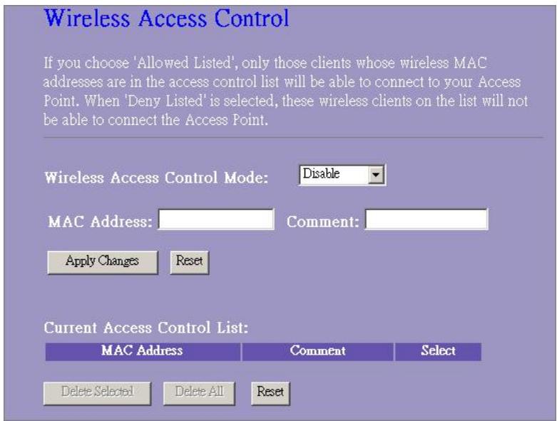
Configuration
| Wireless Access Control Mode | Click on the drop list to choose the access control mode. You may select “Allow listed” to allow those allowed MAC addresses or select “Deny Listed” to ban those MAC addresses from accessing to this device. |
| MAC Address & Comment | To set up the Value of MAC Address & Comment; enter the MAC Address and Comment of station and click Apply Changes to save. |
| Current Access Control list | To Delete the station on the list, Click the check box in the select item and click the “Delete Selected”. If you want to delete all stations on the list, click “Delete All” to remove all of them. |
Click
WDS Setting
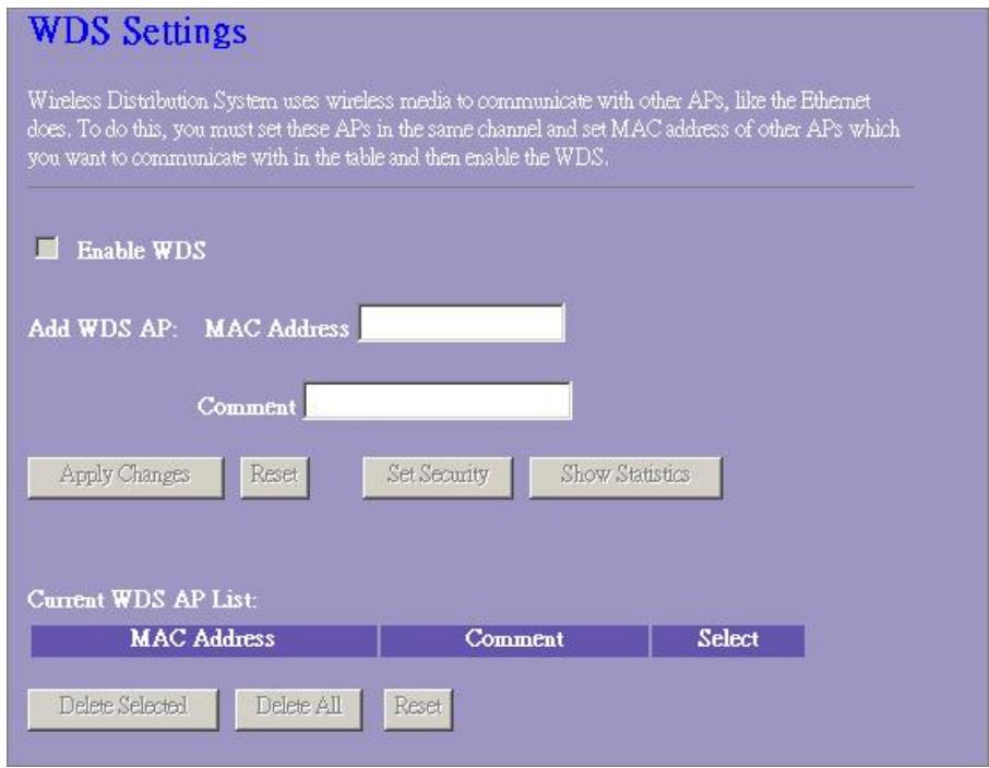
Wireless Distribution System allows the router to communicate with other APs wirelessly. To make it work, you must ensure that these APs and the Router are in the same Channel and add these APs MAC Address and Comment values into the WDS list. Don't Forget to Enable the WDS by click the check box of "Enable WDS" and press "Apply Changes" button to save.
To Delete the AP on the list, Click the check box in the select item and click the "Delete Selected". If you want to delete all APs on the list, click "Delete All" to remove all of them.
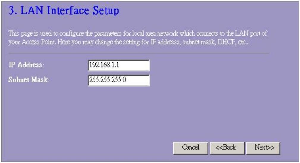
LAN Interface Setup
To set up the configuration of LAN interface, Private IP of you router LAN Port and Subnet mask for your LAN segment.
LAN Interface Setup
This page is used to configure the parameters for local area network which connects to the LAN port of your Access Point. Here you may change the setting for IP addresses, subnet mask, DHCP, etc..
IF Address:
Subnet Mask:
DHCP Server:
DHCP Client Range:
802.1d Spanning Tree:
Enable UPnP
Apply Changes
Reset

192.168.1.100
Disabled
192.168.1.200

192.188.1.200

Show Client

Configuration
| IP address | The IP of your Router LAN port (Default 192.168.1.1) |
| Subnet Mask | Subnet Mask of you LAN (Default 255.255.255.0) |
| DHCP Server | To give your LAN Client an IP, you have to enable “DHCP Server”. If not, manual setting up your client IP is necessary when you want to use the router as your client’s default gateway. |
| DHCP Client Range | Specify the DHCP Client IP address range. You can also click the “Show Client” button to listed those connected DHCP clients. |
| 802.1d Spanning tree | To prevent from network loops and preserve the quality of bridged network |
| Enable UPnP | Mark this checkbox to allow this router to be recognized by UPnP. |
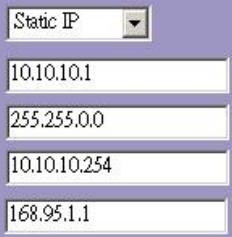
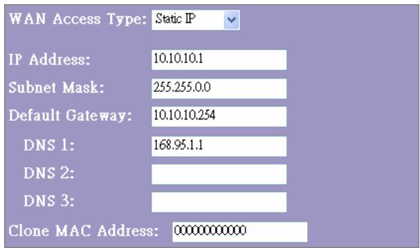
WAN Interface Setup
This page allows users to configure those parameters for connecting to Internet. You may select the WAN Access Type from the drop list and configure parameters for each mode.
Static IP Mode
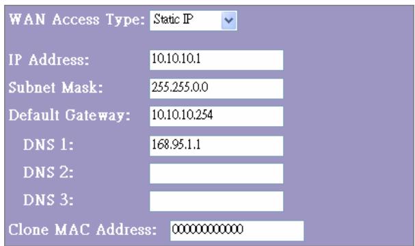
| IP Address, Subnet Mask and Default Gateway | Fill in the IP address, Subnet Mask and Default Gateway that provided by your ISP. |
| DNS 1, 2 and 3 | To specify the DNS, and enter the DNS provided by your ISP in DNS 1 2 3. |
DHCP Client Mode
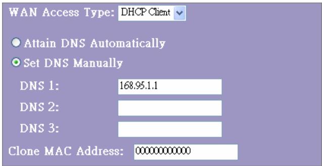
| Attain DNS automatically | If your DNS provide by ISP is dynamic, choose “Attain DNS automatically |
| Set DNS Manually | To specify the DNS, and enter the DNS provided by your ISP in DNS 1 2 3. |
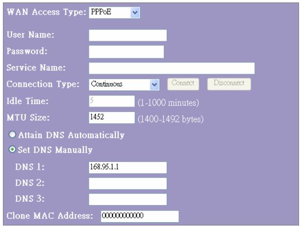
PPPoE Mode
| User Name, password and service name | Fill in the User Name, password and service name that provided by your ISP. |
| Connection Type | “Continuous” is for Always keep connection |
| “Connect on demand” is for bill by connection time. You can set up the Idle time for the value specifies the number of time that elapses before the system automatically disconnects the PPPoE session. | |
| “Manual” To connect to ISP, click “Connect” manually from the WEB user interface. The WAN connection will not be disconnected due to the idle timeout. If the WAN line breaks down and latter links again, the router will not auto-connect to the ISP. | |
| Idle Time: | The value specifies the number of idle time that elapses before the system automatically disconnects the PPPoE session. |
| MTU Size | To Enable the Maximum Transmission Unit of Router setup. Any packet over this number will be chopped up into suitable size before sending. Larger number will enhance the transmission performance. Enter your MTU number in the text-box to set the limitation. |
| Attain DNS automatically: | If your DNS provide by ISP is dynamic, choose “Attain DNS automatically |
| Set DNS Manually | To specify the DNS, and enter the DNS provided by your ISP in DNS 1 2 3. |
PPTP Mode
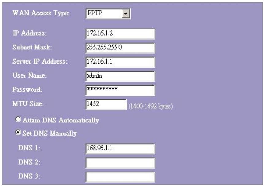
| IP Address, Subnet Mask, Server IP Address, User Name and Password | Fill in the IP address, Subnet Mask, Server IP Address, User Name and password that provided by your ISP. |
| MTU Size | To Enable the Maximum Transmission Unit of Router setup. Any packet over this number will be chopped up into suitable size before sending. Larger number will enhance the transmission performance. Enter your MTU number in the text-box to set the limitation. |
| Attain DNS automatically | If your DNS provide by ISP is dynamic, choose "Attain DNS automatically |
| Set DNS Manually | To specify the DNS, and enter the DNS provided by your ISP in DNS 1 2 3. |
Common configurations for WAN interface
There are some settings are able to be configured on each WAN access types:
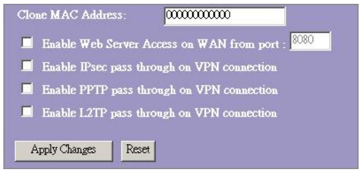
| Enable Web Server Access on WAN from port | To Enable the user to access this Router through Internet, Enter the specific IP and the port number |
| Enable IPsec pass through on VPN connection | Mark the check box to enable IPsec pass through on VPN connection and clear the checkbox to disable. |
| Enable PPTP pass through on VPN connection | Mark the check box to enable PPTP pass through on VPN connection and clear the checkbox to disable. |
| Enable L2TP pass through on VPN connection | Mark the check box to enable L2TP pass through on VPN connection and clear the checkbox to disable. |
| Clone MAC Address | When ISP use MAC address authentication (with DHCP), then the MAC address of the Ethernet card attached to your Cable modem must be registered with the ISP before connecting to the WAN (Internet). If the Ethernet card is changed, the new MAC address must be registered with the ISP.MAC cloning feature allows the MAC address reported by WAN side network interface card to be set to the MAC address already registered with the ISP eliminating the need to register the new MAC address with the ISP. This feature does not change the actual MAC address on the NIC, but instead changes the MAC address reported by Wireless Router to client requests. To Change the MAC address, enter it in the text box. |
Firewall Configuration
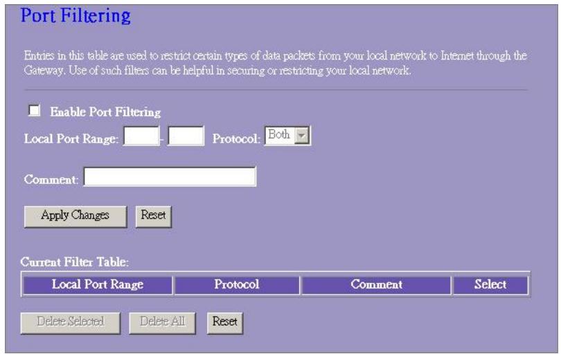
Port Filtering
The firewall could not only obstruct outside intruders from intruding your system, but also restricting the LAN users.
Port Filtering To restrict certain type of data packets from your LAN to Internet through the Router, add them on the Current Filtering Table.
Configuration
STEPS
- Click the check box of "Enable Port Filtering" to enable the function.
- Enter the Port range (EX 25-110), Protocol (UDP/TCP), and comment (EX. E-Mail)
- To Delete the Port range on the list, Click the check box in the select item and click the "Delete Selected". If you want to delete all entries on the list, click "Delete All" to remove all of them.
Click
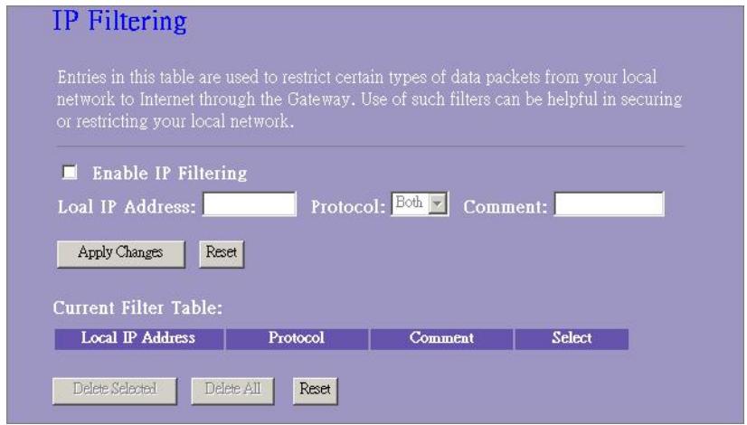
IP filtering
The Wireless Router could filter the outgoing packets for security or management consideration. You can set up the filter against the IP addresses to block specific internal users from accessing the Internet.
Configuration
| STEPS | 1. Click the check box of “Enable IP Filtering” to enable the function. |
| 2. Enter the specific Local IP address (EX 10.10.3.9), Protocol (UDP/TCP), and comment (EX. Peter) | |
| 3. To Delete the IP address on the list, Click the check box in the select item and click the “Delete Selected”. If you want to delete all entries on the list, click “Delete All” to remove all of them. |
Click
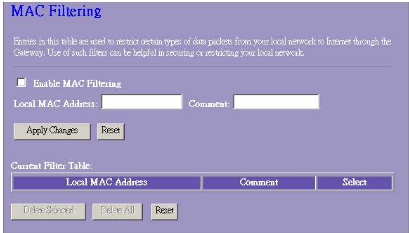
MAC filtering
The Wireless Router could filter the outgoing packets for security or management consideration. You can set up the filter against the MAC addresses to block specific internal users from accessing the Internet.
Configuration
STEPS
- Click the check box of "Enable MAC Filtering" to enable the function.
- Enter the specific MAC address (EX 00:0e:b6:a8:72), and comment (EX. Peter)
- To Delete the MAC address on the list, Click the check box in the select item and click the "Delete Selected". If you want to delete all Entries on the list, click "Delete All" to remove all of them.
Click
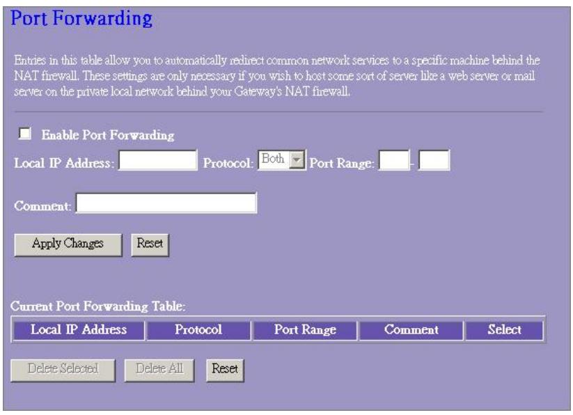
Port forwarding
The Port Forwarding allows you to re-direct a particular range of service port numbers (from the Internet/WAN Ports) to a particular
LAN IP address. It helps you to host some servers behind the router NAT firewall.
Configuration
| STEPS | 1. Click the check box of “Enable port forwarding” to enable the function. |
| 2. Enter the specific IP address (EX 10.10.10.10), Protocol (UDP/TCP), Port range (EX 25-110), and comment (EX. E-Mail) | |
| 3. To Delete the IP address on the table, Click the check box in the select item and click the “Delete Selected”. If you want to delete all Entries on the table, click “Delete All” to remove all of them. |
Click
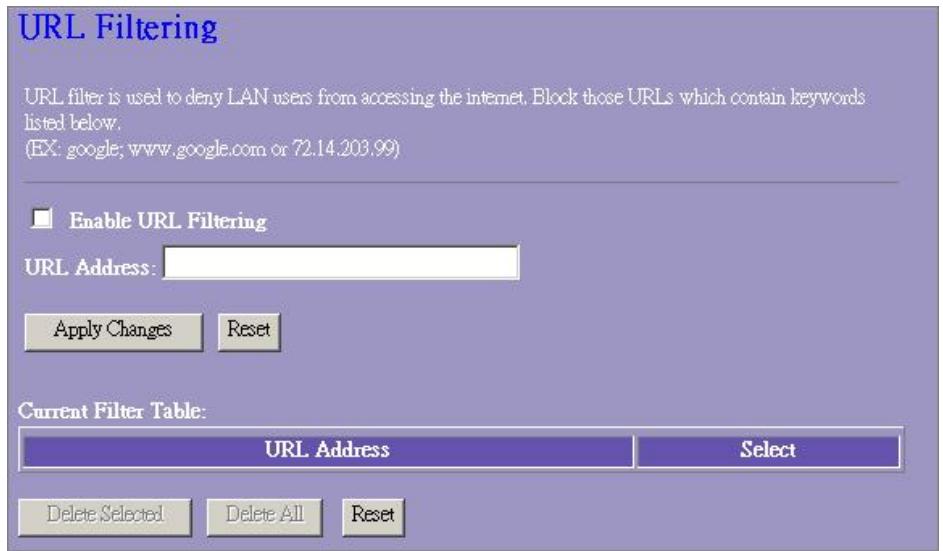
URL Filtering
The URL Filter allows users to prevent certain URL from accessing by users in LAN. This filter will block those URLs that contain certain keywords.
Configuration
| STEPS | 1. Click the check box of “Enable URL Filtering” to enable the function. |
| 2. Enter the URL that is going to be banned. | |
| 3. To Delete the URL on the table, Click the check box in the select item and click the “Delete Selected”. If you want to delete all URLs on the table, click “Delete All” to remove all of them. |
Click
Virtual DMZ
The virtual DMZ is used to enable protocols, which need to open ports on the router. The router will forward all unspecified incoming traffic to the host specified in this page.
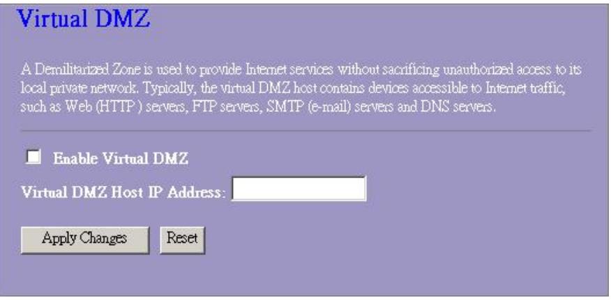
To configure it, enter the Host IP (private IP address) and Click "Apply changes" to enact the setting.
Management
Status
In the home page of the Wireless Router, the left navigation bar shows the options to configure the system. In the right navigation screen is the summary of system status for viewing the configurations.
Status
This page shows the current status and some basic settings of the device.
SYSTEM
Uptime 0day:0h:2m:54s
Firmware Version v1.0
Wireless Configuration
Mode AP Band 2.4 GHz (B+G) SSID WLAN-11g-GW
Channel Number 11
Encryption Disabled
BSSID 00:e0:7d:c0:c7:d1
Associated Clients 0
LAN Configuration
IP Address 192.168.1.1
Subnet Mask 255.255.255.0
DHCP Server Enabled
MAC Address 00:e0:7d:c0:c7:
WAN Configuration
Attain IP Protocol Static IP
IP Address 10.10.10.1
Subnet Mask 255.255.0.0
Default Gateway 10.10.10.254
MAC Address 00:e0:7d:c0:c
23414
WLAN ROUT 54-N
System
| Uptime | The period that you power the device on. |
| Firmware Version | The version of the firmware applied on this device. |
- Wireless Configuration
| Mode | The operation mode of the wireless router |
| Band | The performing band of this wireless router |
| SSID | The name of this wireless network |
| Channel Number | The channel used by the wireless LAN. All devices in the same wireless LAN should user the same channel |
| Encryption | The security encryption status of this wireless network |
| BSSID | The Basic Service Set Identity of this router.(This parameter is the same as the MAC address of LAN port) |
| Associated Clients | The number of associated clients. |
LAN Configuration
| IP Address | IP Address of router |
| Subnet Mask | Subnet Mask of the router |
| DHCP Server | Enabled or Disable of DHCP |
| MAC Address | MAC Address of LAN-port |
WAN Configuration
| Attain IP Protocol | Static IP address |
| IP Address | IP address of WAN-port |
| Subnet Mask | Subnet Mask of WAN-port |
| Default Gateway | Default Gateway of WAN-port |
| MAC Address | MAC Address of WAN-port |
Statistics
On this page, you can monitor the sent & received packets counters of wireless, Ethernet LAN, and Ethernet WAN. To see the latest report, click refresh button.
Statistics
This page shows the packet counters for transmission and reception regarding to wireless and Ethernet networks.
| Wireless LAN | Sent Packets | 145357 |
| Received Packets | 1121 | |
| Ethernet LAN | Sent Packets | 6845 |
| Received Packets | 858102 | |
| Ethernet WAN | Sent Packets | 8285 |
| Received Packets | 0 |
Refresh
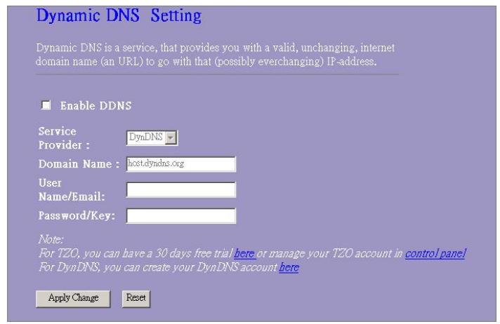
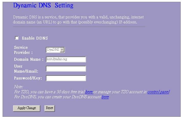
DDNS
This page allows users to connect to DDNS. To enable DDNS, Mark the "Enable DDNS" checkbox. Select the service provider from the drop list. Fill in domain name, username, and password. Click the "Apply Change" button after configuration.
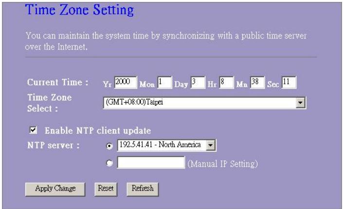
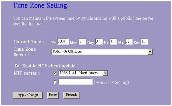
Time Zone Setting
This page allows users to configure the time of the router. To specify manually, fill in the blanks in "Current Time" and click the "Apply Change" button. To synchronize time from a timeserver, please mark the "Enable NTP client update" checkbox, select a NTP server from the drop list or manually enter a NTP server. Click the "Apply Change" button after your configuration.
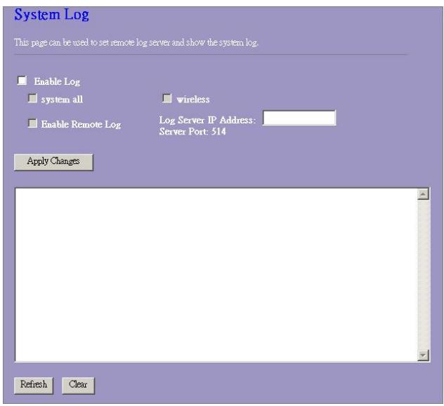
System Log
This System Log page shows the information of the current activities on the router.
To enable system log function:
- Mark the "Enable Log" checkbox.
- To see all information of the system, select the "system all" checkbox.
To see wireless information only, select the "wireless" checkbox. To sent the log information to a certain note, select the "Enable Remote Log" checkbox and fill in the IP address in the "Log Server IP Address" box.
- Click the "Apply Changes" button to activate
You could also click the "Refresh" button to refresh the log information or click the "clear" button to clean the log table.
23414
WLAN ROUT 54-N
Upgrade Firmware
To Upgrade Firmware,
| STEPS | 1. Click “browse...” button to select the firmware you want to upgrade. |
| 2. Click Upload to start the upgrade process. Please don’t close the WEB-browser and wait for process to complete. When Upgrade is completed, you can start to use the router. |
Upgrade Firmware
This page allows you upgrade the Access Point firmware to new version. Please note, do not power off the device during the upload because it may crash the system.
Select File:

Upload
Reset
Save and Reload Settings
To save setting to file, click "Save..." button.
To load setting from file,
- Click "Browse..." on the to select the file
- Click upload to start the process and wait for it to complete
To reset setting to Default, click reset to start the process and it will be completed till the status LED start blinking.
Save/Reload Settings
This page allows you save current settings to a file or reload the settings from the file which was saved previously. Besides, you could reset the current configuration to factory default.
Save Settings to File:
Load Settings from File:
Reset Settings to Default:
Save...

Reset
Password
To set up the Administrator Account information, enter theUsername, New password, and reenter the password on the text box. Don't forget to click the “Apply Changes” to save the configuration.
Password Setup
This page is used to set the account to access the web server of Access Point. Empty user name and password will disable the protection.
User Name:
New Password:
Confirmed
Password:
Apply Changes
Reset
PRODUCT SPECIFICATIONS
| Standard | IEEE802.3, 10BASE-T IEEE802.3u, 100BASE-TX IEEE802.3x full duplex operation and flow control IEEE802.11b wireless LAN infrastructure IEEE802.11g wireless LAN infrastructure |
| Interface | 1 * WAN port 4 * 10/100 RJ-45 Fast Ethernet switching ports Antenna: 802.11b/g wireless reverse SMA detachable |
| WAN Connection | Ethernet 10/100 Mbps |
| Cable Connections | RJ-45 (10BASE-T): Category 3,4,5 UTP RJ-45 (100BASE-TX): Category 5 UTP |
| Network Data Rate | 802.11b: 1, 2, 5.5 and 11Mbps 802.11g: 6, 9, 12, 18, 24, 36, 48, and 54Mbps |
| Transmission Mode | Auto-Negotiation (Full-duplex, Half-duplex) |
| LED indications | System: Power, Status Port (WAN): ACT/LINK Port (LAN): ACT/LINK Port (Wireless): ACT |
| Security | 64/128-bit WEP, WPA (TKIP with IEEE 802.1x), WPA2, AES |
| Receiver Sensitivity | 54Mbps OFDM, 10%PER, -71dBm 11Mbps CCK, 10%PER, -81dBm 1Mbps BPSK, 10%PER, -92dBm |
| Memory | Flash: 2MB NOR type, SDRAM: 8MB |
| Transmit Power | 16dBm~18dBm |
| Range Coverage | Indoor 35~100 meters Outdoor 100~300meters. |
| Emission | FCC CLASS B, CE, VCCI Class B |
| Operating Temperature | 0° ~ 40°C (32° ~ 104°F) |
| Operating Humidity | 10% - 90% |
| Power Supply | External Power Adapter, 12VDC/ 1A |
D
Port LEDs (Wireless)
WLANLED
This page is used to configure the parameters for Internet network which connects to the WAN port of your Access Point. Here you may change the access method to static IP, DHCP, PPPoE or PPTP by click the item value of WAN Access type.
WAN Access Type:
IP Address:
Subnet Mask:
Default Gateway:
DNS:

10.10.10.1
255,255.00
10.10.10.254
168.95.1.1
Cancel
<Back
Next>>
5. Wireless Basic Settings
This page is used to configure the parameters for wireless LAN clients which may connect to your Access Point.
Band:
Mode:
SSID:
Country:
Channel Number:


Cancel
<Back
Next>>
23414
WLAN ROUT 54-N
6. Wireless Security Setup
This page allows you setup the wireless security. Turn on WEP or WPA by using Encryption Keys could prevent any unauthorized access to your wireless network.
Encryption:

Cancel
<Back
Finished
Betriebsmodus
You can setup different modes to LAN and WLAN interface for NAT and bridging function.
Gateway:
In this mode, the device is supposed to connect to internet via ADSL/Cable Modern. The NAT is enabled and PCs in LAN ports share the same IP to ISP through WAN port. The connection type can be setup in WAN page by using PPPOE, DHCP client, PPPT client or static IP.
Bridge:
In this mode, all ethernet ports and wireless interface are bridged together and NAT function is disabled. All the WAN related function and firewall are not supported.
Apply Change

Wireless
Wireless Security Setup
This page allows you setup the wireless security. Turn on WEP or WPA by using Encryption Keys could prevent any unauthorized access to your wireless network.
Encryption:

Set WEP Key
Use 802.1x Authentication
WEP 64bits WEP128bits
WPA Authentication Mode:
Enterprise (RADIUS) Personal (Pre-Shared Key)
WPA Cipher Suite:
TKIP AES
WPA2 Cipher Suite:
TKIP AES
Pre-Shared Key Format:
Passphrase
Pre-Shared Key.

Enable Pre-Authentication
Authentication RADIUS Server
Port 1812 IP address

Password
Note: When encryption WEP is selected, you must set WEPkey value.
Apply Changes Reset
Reset
23414
WLAN ROUT 54-N
Konfiguration
These Sections are very easy to understand. They are intended for the reader who is interested in the following topics:
Statischer IP Modus
This page shows the current status and some basic settings of the device.
SYSTEM
Uptime 0day:0h:2m:54s
Firmware Version v1.0
Wireless Configuration
Mode AP
Band 2.4 GHz ( + ) SSID WLAN-11g-GW
Channel Number 11
Encryption Disabled
BSSID 00:e0:7d:c0:c7:d
Associated Clients 0
LAN Configuration
IP Address 192.168.1.1
Subnet Mask 255.255.255.0
DHCP Server Enabled
MAC Address 00:e0:7d:c0:c7:d
WAN Configuration
Attain IP Protocol Static IP
IP Address 10.10.10.1
Subnet Mask 255.255.0.0
Default Gateway 10.10.10.254
MAC Address 00:e0:7d:c0:c7:d
23414
WLAN ROUT 54-N
System
This page shows the packet counters for transmission and reception regarding to wireless and Ethernet networks.
| Wireless LAN | Sent Packets | 145357 |
| Received Packets | 1121 | |
| Ethernet LAN | Sent Packets | 6845 |
| Received Packets | 858102 | |
| Ethernet WAN | Sent Packets | 8285 |
| Received Packets | 0 |
Refresh
DDNS
These Sections are very easy to understand. They are intended for professionals, students and students of universities and colleges. The sections are organized in two parts: "Verfahren und Praxis" and "Praxis und Verfahren", which is the first part of this book. In these sections, we discuss the basic concepts of the subject, including definitions of the concepts and definitions of the concepts.
These Sections are very easy to understand. They are intended for the user who is interested in the latest news on the NTP Server. These sections are used to describe how the user can use them to monitor and analyze the data that is stored in the NTP Server.
System Log
This page allows you upgrade the Access Point firmware to new version. Please note, do not power off the device during the upload because it may crash the system.
Select File:

Upload
Reset
This page is used to configure the parameters for Internet network which connects to the WAN port of your Access Point. Here you may change the access method to static IP, DHCP, PPPoE or PPTP by click the item value of WAN Access type.
WAN Access Type:
IP Address:
Subnet Mask:
Default Gateway:
DNS:

10.10.10.1
255.255.0.0
10.10.10.254
168.95.1.1

Back
Next>>
5. Wireless Basic Settings
This page is used to configure the parameters for wireless LAN clients which may connect to your Access Point.
Band:
Mode:
SSID:
Country:
Channel Number:


WLAN-11g-GW


Cancel
<Back
Next>>
23414
WLAN ROUT 54-N
6. Wireless Security Setup
This page allows you setup the wireless security. Turn on WEP or WPA by using Encryption Keys could prevent any unauthorized access to your wireless network.
Encryption:

Cancel
<Back
Finished
You can setup different modes to LAN and WLAN interface for NAT and bridging function.
Gateway:
In this mode, the device is supposed to connect to internet via ADSL/Cable Modem. The NAT is enabled and PCs in LAN ports share the same IP to ISP through WAN port. The connection type can be setup in WAN page by using PPPOE, DHCP client, PPPT client or static IP.
Bridge:
In this mode, all ethernet ports and wireless interface are bridged together and NAT function is disabled. All the WAN related function and firewall are not supported.
Apply Change

Sans fil
Puissance desorting RF (RF Output power)
Mode Turbo
Wireless Security Setup
This page allows you setup the wireless security. Turn on WEP or WPA by using Encryption Keys could prevent any unauthorized access to your wireless network.
Encryption:


1x Authentication


WPA Authentication Mode:


WPA Cipher Suite:


WPA2 Cipher Suite:


Pre-Shared Key Format:


Pre-Shared Key:


Enable Pre-Authentication

IP address

Password
Authentication RADIUS Server:

1812 IP address
Passwom
Note: When encryption WEP is selected, you must set WEPkey value.
Apply Changes
Reset
Configuration
This page is used to configure the parameters for local area network which connects to the LAN port of your Access Point. Here you may change the setting for IP addresses, subnet mask, DHCP, etc..
IP Address:
Subnet Mask:
DHCP Server:
DHCP Client Range:
802.1d Spanning Tree:
Enable UPnP
Apply Changes
Reset
192.168.1.1
255.255.255.0
Enabled
192.168.1.100
Disabled
192.168.1.200
Show Client
Configuration de l'interface WAN
Gestion (Management)
État
This page shows the current status and some basic settings of the device.
SYSTEM
Uptime 0day:0h:2m:54s
Firmware Version v1.0
Wireless Configuration
Mode AP
Band 2.4 GHz ( + ) SSID WLAN-11g-GW
Channel Number 11
Encryption Disabled
BSSID 00:e0:7d:c0:c7:d
Associated Clients 0
LAN Configuration
IP Address 192.168.1.1
Subnet Mask 255.255.255.0
DHCP Server Enabled
MAC Address 00:e0:7d:c0:c7:d
WAN Configuration
Attain IP Protocol Static IP
IP Address 10.10.10.1
Subnet Mask 255.255.0.0
Default Gateway 10.10.10.254
MAC Address 00:e0:7d:c0:c7:d
- Systeme
Temps usable (Uptime) Version du micro-logiciel (Firmware version)
This page allows you upgrade the Access Point firmware to new version. Please note, do not power off the device during the upload because it may crash the system.
Select File:

UpLoad
Reset
The setup wizard will guide you to configure access point for first time. Please follow the setup wizard step by step.
Welcome to Setup Wizard.
The Wizard will guide you the through following steps. Begin by clicking on Next.
- Setup Operation Mode
- Choose your Time Zone
- Setup LAN Interface
- Setup WAN Interface
- Wireless LAN Setting
- Wireless Security Setting

You can setup different modes to LAN and WLAN interface for NAT and bridging function.
Gateway:
In this mode, the device is supposed to connect to internet via ADSLCable Modern. The NAT is enabled and PCs in four LAN ports share the same IP to ISP through WAN port. The connection type can be setup in WAN page by using PPPOE, DHCP client, PPTP client or static IP.
Bridge:
In this mode, all ethernet ports and wireless interface are bridged together and NAT function is disabled. All the WAN related function and firewall are not supported.

23414
WLAN ROUT 54-N
This page is used to configure the parameters for Internet network which connects to the WAN port of your Access Point. Here you may change the access method to static IP, DHCP, PPPoE or PPTP by click the item value of WAN Access type.
WAN Access Type:
IP Address:
Subnet Mask:
Default Gateway:
DNS:

10.10.10.1
255.255.00
10.10.10.254
168.95.1.1
Cancel
<Back
Next>>
5. Wireless Basic Settings
This page is used to configure the parameters for wireless LAN clients which may connect to your Access Point.
Band:

Mode:

SSID:

Country:

Channel Number:

Cancel
<<Back
Next>>
23414
WLAN ROUT 54-N
6. Wireless Security Setup
This page allows you setup the wireless security. Turn on WEP or WPA by using Encryption Keys could prevent any unauthorized access to your wireless network.
Encryption:

∴ m : x = 1 或 3x + 4y + 1 = 0

Cancel
Back
Finished
Modo operativo
You can setup different modes to LAN and WLAN interface for NAT and bridging function.
Gateway:
In this mode, the device is supposed to connect to internet via ADSL/Cable Modem. The NAT is enabled and PCs in LAN ports share the same IP to ISP through WAN port. The connection type can be setup in WAN page by using PPPOE, DHCP client, PPTP client or static IP.
Bridge:
In this mode, all ethernet ports and wireless interface are bridged together and NAT function is disabled. All the WAN related function and firewall are not supported.
Apply Change
Reset
Wireless
Alternatively, you can use the parametris to convert a router into a router with only one router. This is possible by using the parameter set in the router configuration. Alternatively, you can use the parametris to convert a router into a router with multiple routers. Alternatively, you can use the parametris to convert a router into a router with multiple routers. Alternatively, you can use the parametris to convert a router into a router with multiple routers. Alternatively, you can use the parametris to convert a router into a router with multiple routers. Alternatively, you can use the parametris to convert a router into a router with multiple routers. Alternatively, you can use the parametris to convert a router into a router with multiple tunnels. Alternatively, you can use the parametris to convert a router into a router with multiple tunnels. Alternatively, you can use the parametris to convert a router into a router with multiple tunnels. Alternatively, you can use the parametris to convert a router into a router with multiple tunnels. Alternatively, you can use the parametris to convert a router into a router with multiple tunnels. Alternatively, you can use the parametris to convert a router into a router with multiple tunnels. Alternatively, you can use the parametris to convert a router into a router with multiple tunnels. Alternatively, you can use the parametris to convert a router into a router with multiple tunnels. Alternatively, you can use the parametris to convert a router into a router with multiple tunnels. Alternatively, you can use the parametris to convert a router into a router with multiple tunnels. Alternatively, you can use the parametris to convert a router into a router with multiple Tunnel's. Alternatively, you can use the parametris to convert a router into a router with multiple Tunnel's. Alternatively, you can use the parametris to convert a router into a router with multiple Tunnel's. Alternatively, you can use the parametris to convert a router into a router with multiple Tunnel's. Alternatively, you can use the parametris to convert a router into a router with multiple Tunnel's. Alternatively, you can use the parametris to convert a router into
Configuración
Wireless Security Setup
This page allows you setup the wireless security. Turn on WEP or WPA by using Encryption Keys could prevent any unauthorized access to your wireless network.
Encryption:


1x Authentication


WPA Authentication Mode:


WPA Cipher Suite:


WPA2 Cipher Suite:


Pre-Shared Key Format:


Pre-Shared Key:


Enable Pre-Authentication

IP address

Password
Authentication RADIUS Server:

1812 IP address
Password
Note: When encryption WEP is selected, you must set WEPkey value.
Apply Changes
Reset
23414
WLAN ROUT 54-N
Configuración
This page is used to configure the parameters for local area network which connects to the LAN port of your Access Point. Here you may change the setting for IP addresses, subnet mask, DHCP, etc..
IP Address:
Subnet Mask:
DHCP Server:
DHCP Client Range:
802.1d Spanning Tree:

Enable UPnP
Apply Changes
Reset


192.168.1.200
Show Client


Configuración
Pulse
Virtual DMZ
A Demilitarized Zone is used to provide Internet services without sacrificing unauthorized access to its local private network. Typically, the virtual DMZ host contains devices accessible to Internet traffic, such as Web (HTTP) servers, FTP servers, SMTP (e-mail) servers and DNS servers.

Enable Virtual DMZ
Virtual DMZ Host IP Address:
Apply Changes
Reset
This page allows you upgrade the Access Point firmware to new version. Please note, do not power off the device during the upload because it may crash the system.
Select File:

Upload
Reset
Guardar y reiniciar
Subnet Mask:255.255.255.0
The setup wizard will guide you to configure access point for first time. Please follow the setup wizard step by step.
Welcome to Setup Wizard.
The Wizard will guide you the through following steps. Begin by clicking on Next.
- Setup Operation Mode
- Choose your Time Zone
- Setup LAN Interface
- Setup WAN Interface
- Wireless LAN Setting
- Wireless Security Setting
Next>>
You can setup different modes to LAN and WLAN interface for NAT and bridging function.
Gateway.
In this mode, the device is supposed to connect to internet via ADSLCable Modem. The NAT is enabled and PCs in four LAN ports share the same IP to ISP through WAN port. The connection type can be setup in WAN page by using PPPOE, DHCP client, PPTP client or static IP.
Bridge:
In this mode, all ethernet ports and wireless interface are bridged together and NAT function is disabled. All the WAN related function and firewall are not supported.
Cancel
Back
Next>>
23414
WLAN ROUT 54-N
This page is used to configure the parameters for Internet network which connects to the WAN port of your Access Point. Here you may change the access method to static IP, DHCP, PPPoE or PPTP by click the item value of WAN Access type.
WAN Access Type:
IP Address:
Subnet Mask:
Default Gateway:
DNS:

10.10.10.1
255.255.0.0
10.10.10.254
168.95.1.1
Cancel
<Back
Next>>
5. Wireless Basic Settings
This page is used to configure the parameters for wireless LAN clients which may connect to your Access Point.
Band:
Mode:
SSID:
Country:
Channel Number:


WLAN-11g-GW


Cancel
<Back
Next>>
23414
WLAN ROUT 54-N
6. Wireless Security Setup
This page allows you setup the wireless security. Turn on WEP or WPA by using Encryption Keys could prevent any unauthorized access to your wireless network.
Encryption:

Cancel
<Back
Finished
Modalità operativa
You can setup different modes to LAN and WLAN interface for NAT and bridging function.
Gateway:
In this mode, the device is supposed to connect to internet via ADSL/Cable Modem. The NAT is enabled and PCs in LAN ports share the same IP to ISP through WAN port. The connection type can be setup in WAN page by using PPPOE, DHCP client, PPTP client or static IP.
Bridge:
In this mode, all ethernet ports and wireless interface are bridged together and NAT function is disabled. All the WAN related function and firewall are not supported.
Apply Change

23414
WLAN ROUT 54-N
Wireless
Wireless Security Setup
This page allows you setup the wireless security. Turn on WEP or WPA by using Encryption Keys could prevent any unauthorized access to your wireless network.
Encryption:

Set WEP Key
Use 802.1x Authentication
WEP 64bits WEP128bits
WPA Authentication Mode:
Enterprise (RADIUS)
Personal (Pre-Shared Key)
WPA Cipher Suite:
TKIP AES
WPA2 Cipher Suite:
TRIP ABS
Pre-Shared Key Format:

Pre-Shared Key:
Enable Pre-Authentication

IP address

Password
Note: When encryption WEP is selected, you must set WEPkey value.

23414
WLAN ROUT 54-N
Configurazione
This page is used to configure the parameters for local area network which connects to the LAN port of your Access Point. Here you may change the setting for IP addresses, subnet mask, DHCP, etc..
IP Address:
Subnet Mask:
DHCP Server:
DHCP Client Range:
802.1d Spanning Tree:
Enable UPnP
Apply Changes
Reset
[92.168.1.1]
255.255.255.0

192.168.1.100
Disabled
192.168.1.200
Show Client
Configurazione
This page shows the current status and some basic settings of the device.
SYSTEM
Uptime 0day:0h:2m:54s
Firmware Version v1.0
Wireless Configuration
Mode AP
Band 2.4 GHz ( + ) SSID WLAN-11g-GW
Channel Number 11
Encryption Disabled
BSSID 00:e0:7d:c0:c7:d
Associated Clients 0
LAN Configuration
IP Address 192.168.1.1
Subnet Mask 255.255.255.0
DHCP Server Enabled
MAC Address 00:e0:7d:c0:c7:d
WAN Configuration
Attain IP Protocol Static IP
IP Address 10.10.10.1
Subnet Mask 255.255.0.0
Default Gateway 10.10.10.25
MAC Address 00:e0:7d:c0:
23414
WLAN ROUT 54-N
- Sistema
This page shows the packet counters for transmission and reception regarding to wireless and Ethernet networks.
| Wireless LAN | Sent Packets | 145357 |
| Received Packets | 1121 | |
| Ethernet LAN | Sent Packets | 6845 |
| Received Packets | 858102 | |
| Ethernet WAN | Sent Packets | 8285 |
| Received Packets | 0 |
Refresh
DDNS
This page allows you upgrade the Access Point firmware to new version. Please note, do not power off the device during the upload because it may crash the system.
Select File:

Upload
Reset
VERPAKKINGSINFORMATIE
Poort-LED's (Wireless)
- WLAN LED
The setup wizard will guide you to configure access point for first time. Please follow the setup wizard step by step.
Welcome to Setup Wizard.
The Wizard will guide you the through following steps. Begin by clicking on Next.
- Setup Operation Mode
- Choose your Time Zone
- Setup LAN Interface
- Setup WAN Interface
- Wireless LAN Setting
- Wireless Security Setting

You can setup different modes to LAN and WLAN interface for NAT and bridging function.
Gateway:
In this mode, the device is supposed to connect to internet via ADSLCable Modem. The NAT is enabled and PCs in four LAN ports share the same IP to ISP through WAN port. The connection type can be setup in WAN page by using PPPOE, DHCP client, PPTP client or static IP.
Bridge:
In this mode, all ethernet ports and wireless interface are bridged together and NAT function is disabled. All the WAN related function and firewall are not supported.

23414
WLAN ROUT 54-N
This page is used to configure the parameters for Internet network which connects to the WAN port of your Access Point. Here you may change the access method to static IP, DHCP, PPPoE or PPTP by click the item value of WAN Access type.
WAN Access Type:
IP Address:
Subnet Mask:
Default Gateway:
DNS:


5. Wireless Basic Settings
This page is used to configure the parameters for wireless LAN clients which may connect to your Access Point.
Band:
Mode:
SSD:
Country:
Channel Number:


23414
WLAN ROUT 54-N
6. Wireless Security Setup
This page allows you setup the wireless security. Turn on WEP or WPA by using Encryption Keys could prevent any unauthorized access to your wireless network.
Encryption:

Cancel
Back
Finished
Bedrijfsmodus
You can setup different modes to LAN and WLAN interface for NAT and bridging function.
Gateway:
In this mode, the device is supposed to connect to internet via ADSL/Cable Modem. The NAT is enabled and PCs in LAN ports share the same IP to ISP through WAN port. The connection type can be setup in WAN page by using PPPOE, DHCP client, PPTP client or static IP.
Bridge:
In this mode, all ethernet ports and wireless interface are bridged together and NAT function is disabled. All the WAN related function and firewall are not supported.
Apply Change
Reset
Draadloos
Wireless Security Setup
This page allows you setup the wireless security. Turn on WEP or WPA by using Encryption Keys could prevent any unauthorized access to your wireless network.
Encryption:

Set WEP Key
Use 802.1x Authentication
WEP 64bits
WEP 128bits
WPA Authentication Mode:
Enterprise (RADIUS)
Personal (Pre-Shared Key)
WPA Cipher Suite:
TKIP AES
WPA2 Cipher Suite:
TKIP AES
Pre-Shared Key Format:
Passphrase
Pre-Shared Key:

Enable Pre-Authentication
Port 1812
IP address

Authentication RADIUS Server.
Note: When encryption WEP is selected, you must set WEPkey value.
Apply Changes Reset
Configuratie
This page is used to configure the parameters for local area network which connects to the LAN port of your Access Point. Here you may change the setting for IP addresses, subnet mask, DHCP, etc..
IP Address:
Subnet Mask:
DHCP Server:
DHCP Client Range:
802.1d Spanning Tree:
Enable UPnP
Apply Changes
192.168.1.1
255.255.255.0


This page shows the current status and some basic settings of the device.
SYSTEM
Uptime 0day:0h:2m:54s
Firmware Version v1.0
Wireless Configuration
Mode AP Band 2.4 GHz ( + ) SSID WLAN-11g-GW
Channel Number 11
Encryption Disabled
BSSID 00:e0:7d:c0:c7:d
Associated Clients 0
LAN Configuration
IP Address 192.168.1.1
Subnet Mask 255.255.255.0
DHCP Server Enabled
MAC Address 00:e0:7d:c0:c7:d1
WAN Configuration
Attain IP Protocol Static IP
IP Address 10.10.10.1
Subnet Mask 255.255.0.0
Default Gateway 10.10.10.254
MAC Address 00:e0:7d:c0:c7:d3
System
| Wireless LAN | Sent Packets | 145357 |
| Received Packets | 1121 | |
| Ethernet LAN | Sent Packets | 6845 |
| Received Packets | 858102 | |
| Ethernet WAN | Sent Packets | 8285 |
| Received Packets | 0 |
DDNS
This page allows you upgrade the Access Point firmware to new version. Please note, do not power off the device during the upload because it may crash the system.
Select File:

Upload
Reset
This page allows you save current settings to a file or reload the settings from the file which was saved previously. Besides, you could reset the current configuration to factory default.
Save Settings to File:
Load Settings from File:
Reset Settings to Default:


Wachtwoord
This page is used to set the account to access the web server of Access Point. Empty user name and password will disable the protection.
User Name:
New Password:
Confirmed
Password:
Apply Changes

Reset
PRODUCTSPECIFICATIONS
| Standaard | IEEE802.3, 10BASE-T IEEE802.3u, 100BASE-TX IEEE802.3x Full-Duplex Operation en Flow Control IEEE802.11b Wireless LAN infrastructureur IEEE802.11g Wireless LAN infrastructureur |
| Interface | 1 * WAN poort 4 * 10/100 RJ-45 Fast Ethernet Switching Ports Antenne: 802.11b/g Wireless Reverse SMA afneembaar |
| WAN verbinding | Ethernet 10/100 Mbps |
| Kabelverbindingen | RJ-45 (10BASE-T): Categorie 3,4,5 UTP RJ-45 (100BASE-TX): Categorie 5 UTP |
| Netwerk datasnelheid | 802.11b: 1, 2, 5.5 en 11Mbps 802,11g: 6, 9, 12, 18, 24, 36, 48 en 54Mbps |
| Transmissiemodus | Auto-Negotiation (Full-Duplex, Half-Duplex) |
| LED-indications | Systeem: Power, Status Port (WAN): ACT/LINK Port (LAN): ACT/LINK Port (Wireless): ACT |
| Beveiling | 64/128-bit WEP, WPA(TKIP met IEEE 802.1x), WPA2, AES |
| Ontvangstgevoeligheid | 54Mbps OFDM, 10%PER, -71dBm 11Mbps CCK, 10%PER, -81dBm 1Mbps BPSK, 10%PER, -92dBm |
| Geheugen | Flash: 2MB NOR type, SDRAM: 8MB |
| Transmissievermogen | 16dBm~18dBm |
| Bereik | binnen 35 - 100 meter buiten 100 - 300 meter |
| Emissie | FCC KLASSE B, CE, VCCI Klasse B |
| Bedrijstemperatuur | 0° ~ 40°C (32° ~ 104°F) |
| Bedrijsvochtigheid | 10% - 90% |
| Voedingsspanning | Externe spanningsadapter, 12VDC/1A |
PT
LEDs de porta (Wireless)
- LED WLAN
This page is used to configure the parameters for Internet network which connects to the WAN port of your Access Point. Here you may change the access method to static IP, DHCP, PPPoE or PPTP by click the item value of WAN Access type.
WAN Access Type:
IP Address:
Subnet Mask:
Default Gateway:
DNS:


5. Wireless Basic Settings
This page is used to configure the parameters for wireless LAN clients which may connect to your Access Point.
Band:
Mode:
SSD:
Country:
Channel Number:


23414
WLAN ROUT 54-N
6. Wireless Security Setup
This page allows you setup the wireless security. Turn on WEP or WPA by using Encryption Keys could prevent any unauthorized access to your wireless network.
Encryption:

Cancel
<Back
Finished
Modo de operacao
You can setup different modes to LAN and WLAN interface for NAT and bridging function.
Gateway:
In this mode, the device is supposed to connect to internet via ADSL/Cable Modem. The NAT is enabled and PCs in LAN ports share the same IP to ISP through WAN port. The connection type can be setup in WAN page by using PPPOE, DHCP client, PPPT client or static IP.
Bridge:
In this mode, all ethernet ports and wireless interface are bridged together and NAT function is disabled. All the WAN related function and firewall are not supported.
Apply Change
Reset
Wireless
Active Wireless Client Table
Wireless Security Setup
This page allows you setup the wireless security. Turn on WEP or WPA by using Encryption Keys could prevent any unauthorized access to your wireless network.


Use 802.1x Authentication
WEP 64bits WEP128bits
WPA Authentication Mode:
Enterprise (RADIUS) Personal (Pre-Shared Key)
WPA Cipher Suite:
TKIP AES
WPA2 Cipher Suite:
TKIP AES
Pre-Shared Key Format:

Pre-Shared Key:

Enable Pre-Authentication
Authentication RADIUS Server
Post 1812 IP address

Note: When encryption WEP is selected, you must set WEPkey value.

23414
WLAN ROUT 54-N
Configuração
This page is used to configure the parameters for local area network which connects to the LAN port of your Access Point. Here you may change the setting for IP addresses, subnet mask, DHCP, etc..
IP Address:
Subnet Mask:
DHCP Server:
DHCP Client Range:
802.1d Spanning Tree:
Enable UPnP
Apply Changes
192.168.1.1
255.255.255.0


Disabled


∴ m = 3/11 ;
Show Client
Configuração
Enable IPsec pass through on VPN connection (Activar Ipseg pass through em ligação VPN)
Enable PPTP pass through on VPN connection (Activar PPTP pass through em ligação VPN)
Enable L2TP pass through on VPN connection (Activar L2TP pass through em ligação VPN)
This page shows the current status and some basic settings of the device.
SYSTEM
Uptime 0day:0h:2m:54s
Firmware Version v1.0
Wireless Configuration
Mode AP
Band 2.4 GHz (B+G)
SSID WLAN-11g-GW
Channel Number 11
Encryption
BSSID 00:e0:7d:c0:c7:d1
Associated Clients 0
LAN Configuration
IP Address 192.168.1.1
Subnet Mask 255.255.255.0
DHCP Server Enabled
MAC Address 00:e0:7d:c0:c7:d1
WAN Configuration
Attain IP Protocol Static IP
IP Address 10.10.10.1
Subnet Mask 255.255.0.0
Default Gateway 10.10.10.254
MAC Address 00:e0:7d:c0:c7:d3
- Sistema
| Wireless LAN | Sent Packets | 145357 |
| Received Packets | 1121 | |
| Ethernet LAN | Sent Packets | 6845 |
| Received Packets | 858102 | |
| Ethernet WAN | Sent Packets | 8285 |
| Received Packets | 0 |
DDNS
Para o upgrade do Firmware
| Upgrade Firmware | |
| This page allows you upgrade the Access Point firmware to new version. Please note, do not power off the device during the upload because it may crash the system. | |
| Select File: | Browse... |
| Upload | Reset |
This page allows you save current settings to a file or reload the settings from the file which was saved previously. Besides, you could reset the current configuration to factory default.
Save Settings to File:
Load Settings from File:
Reset Settings to Default:


Palavra-passe
This page is used to set the account to access the web server of Access Point. Empty user name and password will disable the protection.
User Name:
New Password:
Confirmed
Password:
Apply Changes

Reset
Copyright © 2007, All Rights Reserved.
INFORMACJE O OPAKOWANIU
The setup wizard will guide you to configure access point for first time. Please follow the setup wizard step by step.
Welcome to Setup Wizard.
The Wizard will guide you the through following steps. Begin by clicking on Next.
- Setup Operation Mode
- Choose your Time Zone
- Setup LAN Interface
- Setup WAN Interface
- Wireless LAN Setting
- Wireless Security Setting

You can setup different modes to LAN and WLAN interface for NAT and bridging function.
Gateway:
In this mode, the device is supposed to connect to internet via ADSLCable Modem. The NAT is enabled and PCs in four LAN ports share the same IP to ISP through WAN port. The connection type can be setup in WAN page by using PPPOE, DHCP client, PPTP client or static IP.
Bridge:
In this mode, all ethernet ports and wireless interface are bridged together and NAT function is disabled. All the WAN related function and firewall are not supported.
Cancel
Back
Next>>
1
23414
WLAN ROUT 54-N
This page is used to configure the parameters for Internet network which connects to the WAN port of your Access Point. Here you may change the access method to static IP, DHCP, PPPoE or PPTP by click the item value of WAN Access type.
WAN Access Type:
IP Address:
Subnet Mask:
Default Gateway:
DNS:


5. Wireless Basic Settings
This page is used to configure the parameters for wireless LAN clients which may connect to your Access Point.
Band:
Mode:
SSD:
Country:
Channel Number:


23414
WLAN ROUT 54-N
6. Wireless Security Setup
This page allows you setup the wireless security. Turn on WEP or WPA by using Encryption Keys could prevent any unauthorized access to your wireless network.
Encryption:

Cancel
Back
Finished
Operation Mode (Tryb pracy)
You can setup different modes to LAN and WLAN interface for NAT and bridging function.
Gateway:
In this mode, the device is supposed to connect to internet via ADSL/Cable Modem. The NAT is enabled and PCs in LAN ports share the same IP to ISP through WAN port. The connection type can be setup in WAN page by using PPPOE, DHCP client, PPTP client or static IP.
Bridge:
In this mode, all ethernet ports and wireless interface are bridged together and NAT function is disabled. All the WAN related function and firewall are not supported.
Apply Change
Reset
Wireless Security Setup
This page allows you setup the wireless security. Turn on WEP or WPA by using Encryption Keys could prevent any unauthorized access to your wireless network.
Encryption:

Set WEP Key.
Use 802.1x Authentication
WEP 64bits WEP128bits
WPA Authentication Mode:
Enterprise (RADIUS) Personal (Pre-Shared Key)
WPA Cipher Suite:
TKIP AES
WPA2 Cipher Suite:
TKIP AES
Pre-Shared Key Format:
Passphrase
Pre-Shared Key:

Enable Pre-Authentication
Authentication RADIUS Server:
Port 1812 IP address Password
Note: When encryption WEP is selected, you must set WEPkey value.
Apply Changes Reset
23414
WLAN ROUT 54-N
Konfiguracja
This page is used to configure the parameters for local area network which connects to the LAN port of your Access Point. Here you may change the setting for IP addresses, subnet mask, DHCP, etc..
IP Address:
Subnet Mask:
DHCP Server:
DHCP Client Range:
802.1d Spanning Tree:

Enable UPnP
Apply Changes
Reset
192.168.1.1
255.255.255.0


Konfiguracja
This page allows you upgrade the Access Point firmware to new version. Please note, do not power off the device during the upload because it may crash the system.
Select File:

Upload
Reset
This page allows you save current settings to a file or reload the settings from the file which was saved previously. Besides, you could reset the current configuration to factory default.
Save Settings to File:
Load Settings from File:
Reset Settings to Default:


Password (Haslo)
This page is used to set the account to access the web server of Access Point. Empty user name and password will disable the protection.
User Name:
New Password:
Confirmed
Password:
Apply Changes

SPECYFIKACJA PRODUKTU
Port-LED'er (Wireless)
- WLAN-LED
This page is used to configure the parameters for Internet network which connects to the WAN port of your Access Point. Here you may change the access method to static IP, DHCP, PPPoE or PPTP by click the item value of WAN Access type.
WAN Access Type:
IP Address:
Subnet Mask:
Default Gateway:
DNS:
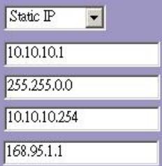

5. Wireless Basic Settings
This page is used to configure the parameters for wireless LAN clients which may connect to your Access Point.
Band:
Mode:
SSID:
Country:
Channel Number:


23414
WLAN ROUT 54-N
6. Wireless Security Setup
This page allows you setup the wireless security. Turn on WEP or WPA by using Encryption Keys could prevent any unauthorized access to your wireless network.
Encryption:

Cancel
<Back
Finished
Driftstilstand
You can setup different modes to LAN and WLAN interface for NAT and bridging function.
Gateway:
In this mode, the device is supposed to connect to internet via ADSL/Cable Modem. The NAT is enabled and PCs in LAN ports share the same IP to ISP through WAN port. The connection type can be setup in WAN page by using PPPOE, DHCP client, PPTP client or static IP.
Bridge:
In this mode, all ethernet ports and wireless interface are bridged together and NAT function is disabled. All the WAN related function and firewall are not supported.
Apply Change
Reset
Tradløs
Wireless Security Setup
This page allows you setup the wireless security. Turn on WEP or WPA by using Encryption Keys could prevent any unauthorized access to your wireless network.


Use 802.1x Authentication
WEP 64bits WEP128bits
WPA Authentication Mode:
Enterprise (RADIUS) Personal (Pre-Shared Key)
WPA Cipher Suite:
TKIP AES
WPA2 Cipher Suite:
TKIF AES
Pre-Shared Key Format:

Pre-Shared Key:

Enable Pre-Authentication
Authentication RADIUS Server:
Port 1812 IP address

Note: When encryption WEP is selected, you must set WEPkey value.

23414
WLAN ROUT 54-N
Konfiguration
This page is used to configure the parameters for local area network which connects to the LAN port of your Access Point. Here you may change the setting for IP addresses, subnet mask, DHCP, etc..
IP Address:
Subnet Mask:
DHCP Server:
DHCP Client Range:
802.1d Spanning Tree:
Enable UPnP
Apply Changes
192.168.1.1
255.255.255.0
Enabled
192.168.1.100
Disabled
2 : x ( x) = y ( x) : 2 : x ( x) = y ( x) : 2 : y ( x) = x ( x) : 2 : x ( x) = y ( x) : 2 : y ( x) = x ( x)
192.168.1.200
Show Client
Konfiguration
WAN-portens standardgateway.
MAC-adresse
WAN-portens MAC-adresse.
Statistik
This page allows you upgrade the Access Point firmware to new version. Please note, do not power off the device during the upload because it may crash the system.
Select File:

Upload
Reset
Copyright © 2007, All Rights Reserved.
FÖRPACKINGSINFORMATION
The setup wizard will guide you to configure access point for first time. Please follow the setup wizard step by step.
Welcome to Setup Wizard.
The Wizard will guide you the through following steps. Begin by clicking on Next.
- Setup Operation Mode
- Choose your Time Zone
- Setup LAN Interface
- Setup WAN Interface
- Wireless LAN Setting
- Wireless Security Setting

You can setup different modes to LAN and WLAN interface for NAT and bridging function.
Gateway:
In this mode, the device is supposed to connect to internet via ADSLCable Modem. The NAT is enabled and PCs in four LAN ports share the same IP to ISP through WAN port. The connection type can be setup in WAN page by using PPPOE, DHCP client, PPTP client or static IP.
Bridge:
In this mode, all ethernet ports and wireless interface are bridged together and NAT function is disabled. All the WAN related function and firewall are not supported.

23414
WLAN ROUT 54-N
This page is used to configure the parameters for Internet network which connects to the WAN port of your Access Point. Here you may change the access method to static IP, DHCP, PPPoE or PPTP by click the item value of WAN Access type.
WAN Access Type:
IP Address:
Subnet Mask:
Default Gateway:
DNS:


5. Wireless Basic Settings
This page is used to configure the parameters for wireless LAN clients which may connect to your Access Point.
Band:
Mode:
SSD:
Country:
Channel Number:


23414
WLAN ROUT 54-N
6. Wireless Security Setup
This page allows you setup the wireless security. Turn on WEP or WPA by using Encryption Keys could prevent any unauthorized access to your wireless network.
Encryption: None
Cancel
Back
Finished
Driftsläge
You can setup different modes to LAN and WLAN interface for NAT and bridging function.
Gateway:
In this mode, the device is supposed to connect to internet via ADSL/Cable Modem. The NAT is enabled and PCs in LAN ports share the same IP to ISP through WAN port. The connection type can be setup in WAN page by using PPPOE, DHCP client, PPTP client or static IP.
Bridge:
In this mode, all ethernet ports and wireless interface are bridged together and NAT function is disabled. All the WAN related function and firewall are not supported.
Apply Change
Reset
Trädlös
Wireless Security Setup
This page allows you setup the wireless security. Turn on WEP or WPA by using Encryption Keys could prevent any unauthorized access to your wireless network.
Encryption:

Set WEP Key
Use 802.1x Authentication
WEP 64bits WEP128bits
WPA Authentication Mode:
Enterprise (RADIUS) Personal (Pre-Shared Key)
WPA Cipher Suite:
TKIP AES
WPA2 Cipher Suite:
TKIP AES
Pre-Shared Key Format:
Passphrase
Pre-Shared Key:

Enable Pre-Authentication
Authentication RADIUS Server:
Port 1812 IP address Password
Note: When encryption WEP is selected, you must set WEPkey value.
Apply Changes Reset
23414
WLAN ROUT 54-N
Konfiguration
This page is used to configure the parameters for local area network which connects to the LAN port of your Access Point. Here you may change the setting for IP addresses, subnet mask, DHCP, etc..
IP Address:
Subnet Mask:
DHCP Server:
DHCP Client Range:
802.1d Spanning Tree:

Enable UPnP

ply Changes

192.16
255.255.255.0


Konfiguration
This page allows you upgrade the Access Point firmware to new version. Please note, do not power off the device during the upload because it may crash the system.
Select File:

Upload
Reset
Information in this document is subject to change without notice. The manufacturer does not make any representations or warranties (implied or otherwise) regarding the accuracy and completeness of this document and shall in no event be liable for any loss of profit or any commercial damages, including but not limited to special, incidental, consequential, or other damages. No part of this document may be reproduced or transmitted in any form, electronic or mechanical, by any means, including photocopying, recording or information recording and retrieval systems without the expressed written permission of the manufacturer. All brand names and product names mentioned in this document are trademarks, or registered trademarks of their respective holders.


- WLAN ROUTER 802.11G , 54 MBIT/S
- TRADEMARKS
- 23414
- WLAN ROUT 54-N
- GB
- UNPACKING INFORMATION
- INTRODUCTION TO WIRELESS ROUTER
- GENERAL DESCRIPTION
- KEY FEATURES
- THE FRONT PANEL
- LED DEFINITION
- SYSTEM LEDS
- PORT LEDS (WIRELESS)
- PORT LEDS (WAN)
- PORT LEDS (LAN)
- THE REAR PANEL
- POWER CONNECTION
- PLACEMENT (OPTIONAL)
- DESKTOP OPTION
- WALL-MOUNT OPTION
- STAND OPTION
- INSTALLING AND USING WIRELESS ROUTER
- NETWORK CONFIGURATION SETUP
- COMPUTER CONFIGURATION SETUP
- NOTE
- PROCEDURES TO CONFIGURE IP ADDRESSES FOR YOUR COMPUTER
- MANAGEMENT
- WIRELESS ROUTER CONFIGURATION SETUP
- THE GRAPHIC USER INTERFACE
- SETUP WIZARD
- OPERATION MODE
- WAN INTERFACE SETUP
- WIRELESS BASIC SETTINGS
- WIRELESS SECURITY SETUP
- WIRELESS
- BASIC SETTINGS
- CONFIGURATION
- ACTIVE WIRELESS CLIENT TABLE
- ADVANCED SETTINGS
- WIRELESS ADVANCED SETTINGS
- SECURITY
- ACCESS CONTROL
- WDS SETTING
- LAN INTERFACE SETUP
- STATIC IP MODE
- DHCP CLIENT MODE
- PPTP MODE
- COMMON CONFIGURATIONS FOR WAN INTERFACE
- FIREWALL CONFIGURATION
- PORT FILTERING
- STEPS
- IP FILTERING
- MAC FILTERING
- PORT FORWARDING
- URL FILTERING
- VIRTUAL DMZ
- STATUS
- SYSTEM
- WIRELESS CONFIGURATION
- LAN CONFIGURATION
- WAN CONFIGURATION
- STATISTICS
- DDNS
- TIME ZONE SETTING
- SYSTEM LOG
- UPGRADE FIRMWARE
- SAVE AND RELOAD SETTINGS
- SAVE/RELOAD SETTINGS
- PASSWORD
- PASSWORD SETUP
- PRODUCT SPECIFICATIONS
- D
- BETRIEBSMODUS
- STATISCHER IP MODUS
- SANS FIL
- CONFIGURATION DE L'INTERFACE WAN
- GESTION (MANAGEMENT)
- ÉTAT
- SYSTEME
- MODO OPERATIVO
- CONFIGURACIÓN
- GUARDAR Y REINICIAR
- MODALITÀ OPERATIVA
- CONFIGURAZIONE
- SISTEMA
- VERPAKKINGSINFORMATIE
- POORT-LED'S (WIRELESS)
- BEDRIJFSMODUS
- DRAADLOOS
- WACHTWOORD
- PRODUCTSPECIFICATIONS
- PT
- LEDS DE PORTA (WIRELESS)
- MODO DE OPERACAO
- PALAVRA-PASSE
- INFORMACJE O OPAKOWANIU
- OPERATION MODE (TRYB PRACY)
- PASSWORD (HASLO)
- SPECYFIKACJA PRODUKTU
- PORT-LED'ER (WIRELESS)
- DRIFTSTILSTAND
- TRADLØS
- MAC-ADRESSE
- STATISTIK
- FÖRPACKINGSINFORMATION
- DRIFTSLÄGE
- TRÄDLÖS
Brand : VIVANCO
Model : WLAN ROUT 54-N
Category : WLAN Router