
MDE 1200 - Drill AEG - Free user manual and instructions
Find the device manual for free MDE 1200 AEG in PDF.
| Product type | Magnetic drill press |
| Brand | AEG |
| Model | MDE 1200 |
| Rated power input | 1200 W |
| Magnet power | 50 W |
| Max magnetic force | 10 kN |
| No-load speed | 300 - 640 min⁻¹ |
| Load speed | 170 - 330 min⁻¹ |
| Stroke | 120 mm |
| Support height (min) | 410 mm |
| Support height (max) | 530 mm |
| Magnet foot dimensions | 160 x 80 mm |
| Max drilling diameter (core drill) | 42 mm |
| Max material thickness | 50 mm |
| Spindle holder | 1/2" x 20 Gg |
| Weight | 10 kg |
| Supply voltage | 230 - 240 V, 50 Hz |
| Sound level (LpA) | 83 dB(A) |
| Vibration (hand-arm) | < 2,5 m/s² |
| Protection | Double insulation, interference suppression according to EN 55014 |
| Safety | Main switch, thermal circuit breaker, magnet acoustic signal, safety chain |
| Maintenance | Rack lubrication, carriage greasing with Molykote |
| Included accessories | Safety chain, fork wrench, Allen key |
| Spare parts | Available from AEG after-sales service (see manual) |
Frequently Asked Questions - MDE 1200 AEG
User questions about MDE 1200 AEG
0 question about this device. Answer the ones you know or ask your own.
Ask a new question about this device
Download the instructions for your Drill in PDF format for free! Find your manual MDE 1200 - AEG and take your electronic device back in hand. On this page are published all the documents necessary for the use of your device. MDE 1200 by AEG.
USER MANUAL MDE 1200 AEG
GB Instructions for use
Please read and save these instructions.
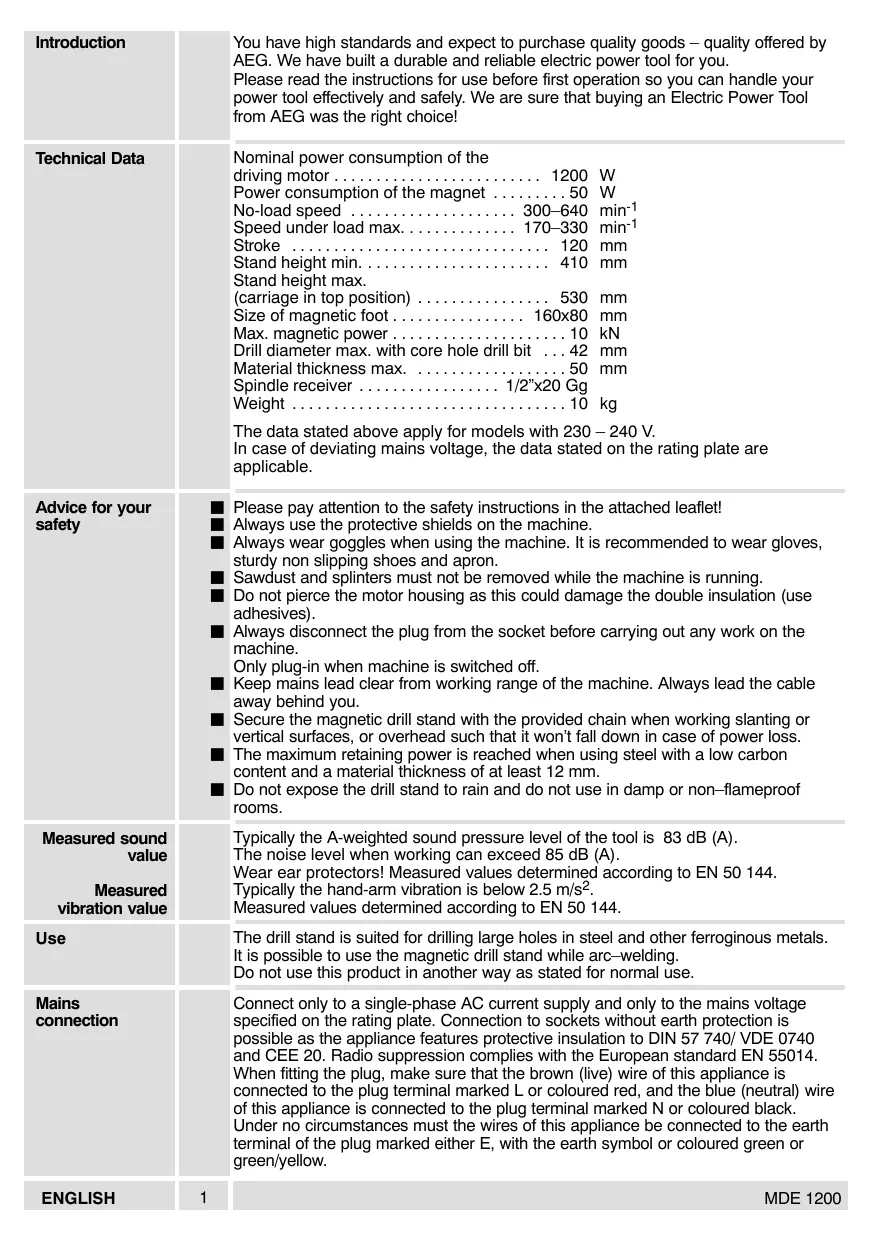
| Introduction | You have high standards and expect to purchase quality goods - quality offered by AEG. We have built a durable and reliable electric power tool for you. Please read the instructions for use before first operation so you can handle your power tool effectively and safely. We are sure that buying an Electric Power Tool from AEG was the right choice! |
| Technical Data | Nominal power consumption of the driving motor 1200 W Power consumption of the magnet 50 W No-load speed 300-640 min-1 Speed under load max 170-330 min-1 Stroke 120 mm Stand height min 410 mm Stand height max. (carriage in top position) 530 mm Size of magnetic foot 160x80 mm Max. magnetic power 10 kN Drill diameter max. with core hole drill bit 42 mm Material thickness max. 50 mm Spindle receiver 1/2"×20 Gg Weight 10 kg The data stated above apply for models with 230 - 240 V. In case of deviating mains voltage, the data stated on the rating plate are applicable. |
| Advice for your safety | Please pay attention to the safety instructions in the attached leaflet! Always use the protective shields on the machine. Always wear goggles when using the machine. It is recommended to wear gloves, sturdy non-slipping shoes and apron. Sawdust and splinters must not be removed while the machine is running. Do not pierce the motor housing as this could damage the double insulation (use adhesives). Always disconnect the plug from the socket before carrying out any work on the machine. Only plug-in when machine is switched off. Keep mains lead clear from working range of the machine. Always lead the cable away behind you. Secure the magnetic drill stand with the provided chain when working slanting or vertical surfaces, or overhead such that it won't fall down in case of power loss. The maximum retaining power is reached when using steel with a low carbon content and a material thickness of at least 12 mm. Do not expose the drill stand to rain and do not use in damp or non-flameproof rooms. |
| Measured sound value | Typically the A-weighted sound pressure level of the tool is 83 dB (A). The noise level when working can exceed 85 dB (A). Wear ear protectors! Measured values determined according to EN 50 144. Typically the hand-arm vibration is below 2.5 m/s². Measured values determined according to EN 50 144. |
| Measured vibration value | |
| Use | The drill stand is suited for drilling large holes in steel and other ferroginous metals. It is possible to use the magnetic drill stand while arc-welding. Do not use this product in another way as stated for normal use. |
| Mains connection | Connect only to a single-phase AC current supply and only to the mains voltage specified on the rating plate. Connection to sockets without earth protection is possible as the appliance features protective insulation to DIN 57 740/ VDE 0740 and CEE 20. Radio suppression complies with the European standard EN 55014. When fitting the plug, make sure that the brown (live) wire of this appliance is connected to the plug terminal marked L or coloured red, and the blue (neutral) wire of this appliance is connected to the plug terminal marked N or coloured black. Under no circumstances must the wires of this appliance be connected to the earth terminal of the plug marked either E, with the earth symbol or coloured green or green/yellow. |
| ENGLISH | 1 MDE 1200 |
Modifications: Text, diagrams and data are correct at the time of printing. In the interest of continuous improvement of our products, technical specifications are subject to alteration without prior notice.
| Setting the free motion of the slide | Always disconnect the plug from the socket before carrying out any work on the machine. The carriage is adjusted by the factory such that it will stop in any position and not move down by the weight of the machine. In case that the carriage play must be adjusted, proceed as follows: Loosen the locking nuts with fork wrench SW8, adjust the carriage play with Allen key size 2.5, and re-tighten the locking nuts. | |
| Safety chain | Secure the magnetic drill stand with the provided chain when working slanting or vertical surfaces, or overhead such that it won't fall down in case of power loss. The safety chain must be applied such that the drill stand will move away from the user in case of power loss. | |
| Starting to work | For optimum operating safety the magnetic drill stand is equipped with a main switch. MDE 1200 is also equipped with a temperature-controlled overload protection. | |
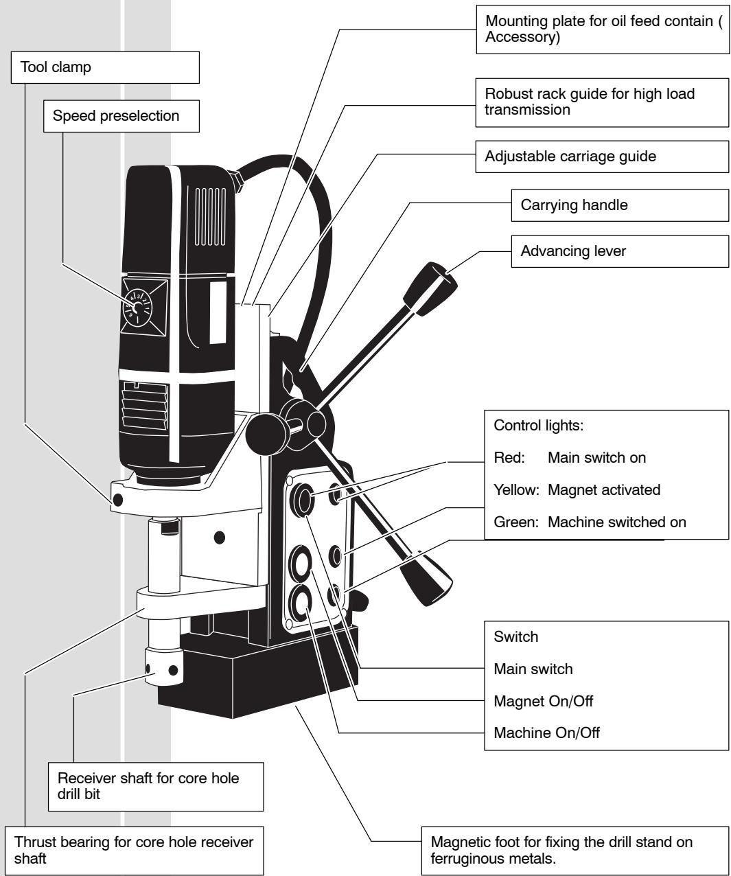
| Switching on the stand | Depress the black push button. The red control light will turn on. It is possible to press the other buttons. | |
| Switching on the magnet | Depress the yellow push–button for magnetic field to build up. The yellow control light is on. | |
| Switching on the machine | Depress the green push–button. The green controlwill come and the drill will start. | |
| Switching off | Depress the green push–button. The drill will turn off.. | |
| Switching off the machine | Depress the yellow push–button. A long signal tone is audible. The magnetic field dies away after approx. 3 seconds. | |
| Switching off the magnet | Depress the yellow push–button. A long signal tone is audible. The magnetic field dies away after approx. 3 seconds. | |
| ENGLISH | 3 | MDE 1200 |
| Switching off the stand | Release the black buttom Magnet and machine will turn off! | |
| For safety reasons, the push-button of the main switch is recessed when switched on. If the machine is not used for a longer period while the magnetic field is activated, a short-interval signal tone indicates this state every 5 minutes. Motor protection device controlled by motor load – heat controlled shut-off if overloading is great. The machine will slowly continue to run in order to cool the motor down. After sufficient cooling machine can be restarted by switching off and on again. | ||
| Setting the no-load speed | Speed pre-selection with setting wheel. A = lowest speed ...... G = highest speed .... | The table shows standard values when using core hole drills. |
| Inserting tools | Always disconnect the plug from the socket before carrying out any work on the machine. The receiver shaft for core hole drill bits must be mounted. 1. Insert the brad point into the receiver shaft. 2. Insert the core hole drill bit into the receiver shaft. The flattened sides must face the borings in the fixing screws. 3. Fasten the core hole drill bit with the two screws. | |
| Inserting a core hole drill bit | ||
| Drilling | Clean the surface of the workpiece. Remove any rust, dirt, or grease. If necessary, remove any unevennesses as well as welding leftovers. A thin layer of grease does not matter. Punch-mark the spot to be drilled and apply the drill stand with the drill tip above the punch mark. Switch on the main switch and the magnet switch to check perfect fixing of the drill stand. | |
| ENGLISH | 4 | MDE 1200 |
EC-DECLARATION OF CONFORMITY
We declare under our sole responsibility that this product is in conformity with the following standards or standardized documents.
EN 50144, EN 55014-1, EN 55014-2, EN 61000-3-2, EN 61000-3-3, in accordance with the regulations 98/37/EC, 73/23/EEC, 89/336/EEC
DEUTSCH
DECLARATION "CE" DE CONFORMITÉ
98/37/EY, 73/23/ETY, 89/336/ETY
GREEK
H H YMBATIKOTHTO
uneuohvoc oTTO pioov auto evai
xataoxeuaaemuo uopwva eTouc EEn xavoviauoc n
xataoxeuaotixec ouotaaeiC: EN 50144, EN 55014-1, EN 55014-2, EN 61000-3-2, EN 61000-3-3, xata tci
diataEic Tov xavoviaow mc Koivc Ayopac 98/37/EK,
73/23/EOK, 89/336/EOK
Rainer Warnicki
Manager Product Marketing and Development


Atlas Copco
Copyright 2003
Atlas Copco Electric Tools GmbH
P.O.Box 320
D-71361 Winnenden Germany
www.atlascopco.de


Brand : AEG
Model : MDE 1200
Category : Drill