
LHS5500 - Log splitter AL-KO - Free user manual and instructions
Find the device manual for free LHS5500 AL-KO in PDF.

| Product type | Electric log splitter |
| Brand | AL-KO |
| Model | LHS5500 |
| Supply voltage | 230 V / 50 Hz |
| Recommended mains fuse | 16 A |
| Minimum cross-section of connection cable | 2,5 mm² |
| Maximum cable length | 10 m |
| Hydraulic oil type | HLP 46 |
| Guaranteed acoustic power level | 88 dB(A) |
| Use | Private, garden and home |
| Main function | Log splitting |
| Safety devices | Engine safety switch, two-handed control, hand protection, automatic stop in high position |
| Equipment | Swivelling table, splitting cross, adjustable holding claws, transport handle, wheels |
| Maintenance | Lubrication of the splitting column before each use, checking the oil level, sharpening of the splitting wedge |
| Spare parts | Use exclusively AL-KO original parts |
| Repairs | Entrust to an authorised professional |
| Minimum age of use | 18 years |
| Environmental protection | Do not dispose of with household waste, recyclable |
Frequently Asked Questions - LHS5500 AL-KO
User questions about LHS5500 AL-KO
0 question about this device. Answer the ones you know or ask your own.
Ask a new question about this device
Download the instructions for your Log splitter in PDF format for free! Find your manual LHS5500 - AL-KO and take your electronic device back in hand. On this page are published all the documents necessary for the use of your device. LHS5500 by AL-KO.
USER MANUAL LHS5500 AL-KO
INFORMATION I MANUALS I SERVICE
HOLZSPALTER
LHS 5500 / LHS 6000 / LHS 7000
Betriebsanleitung


Copyright 2010
AL-KO KOBER GROUP Kottz, Germany
This documentation or excerpts therefrom may not be reproduced or disclosed to third parties without the express permission of the AL-KO KOBER GROUP.
A
LHS 5500
LHS 6000, LHS 7000
B
Art.-Nr.: 112455
Art.-Nr.: 112454
C
| i | |||
| Typ Art. Nr. | LHS 5500 112 424 | LHS 6000 112 427 | LHS 7000 112 428 |
| 230 V~/ 50 Hz | 230 V~/ 50 Hz | 400 V 3~/ 50 Hz | |
| 3000 W S6 40% | 3000 W S6 40% | 3500 W S6 40% | |
| max. 5,5 t | max. 6 t | max. 7 t | |
| max. 320 mm | max. 320 mm | max. 320 mm | |
| max. 570/810/1050 mm | max. 550/1050 mm | max. 550/1050 mm | |
| 23,2 MPa (232 bar) | 22,4 MPa (224 bar) | 26,2 MPa (262 bar) | |
| 4 I | 5,5 I | 5,5 I | |
| max. 30 s | max. 33 s | max. 33 s | |
| II / IP 54 | II / IP 54 | II / IP 54 | |
| 114 kg | 135 kg | 133 kg | |
Sicherheitshinweise
Read the operating manual and adhere to the instructions therein at all times.
Retain the manual for later use and pass on to the future owner in the case of resale of the unit.
Observe all safety and warning instructions on the unit.
Technical data relating to your log splitter can be found at the beginning of the operating manual.
Symbols
On the unit

Read the operating manual before start-up
Ensure that other persons are kept out of the danger zone when starting the unit
Warning! Danger!
Keep hands away from the splitting wedge
Pull out the mains power plug prior to all service and maintenance work
When transporting, move the splitting blade right down and tie the operating levers together.

Wear protective gloves

Wear safety shoes

Wear eye protection

Warning!
Protection class criteria can only be maintained if original insulation material is used (in cases where repairs are necessary) and insulation distances are not changed.
In this operating manual

Caution!
Indicates working and operating procedures that must be strictly adhered to rule out any risk to persons.

Warning!
Contains information that must be observed to prevent damage to the unit.

Note:
Indicates technical requirements that should be given particular attention.
General safety instructions
Children, adolescents under 18 years of age and persons under the influence of alcohol, drugs or medicaments are prohibited from using the unit. Local regulations will indicate the minimum legal age requirements governing the user.
Accident prevention regulations must be observed.

Safety measures
Only one person is permitted to operate the log splitter.
Safety shoes, protective gloves and eye protection should be worn. A risk of injury exists emanating from timber splinters.
Clothing should be practical (close fitting) and should not hinder the wearer. A hair net must be worn to retain long hair.
Never reach into active range of the moving splitting wedge.
The log splitter should only be operated when it is assembled completely and both the log splitter and connection cable are free of damage.
Damaged protective fittings should only be replaced by a specialist firm or workshop.
The log splitter should only be operated with original spare parts.
The log splitter should be disconnected from the mains power supply for:
service work
adjustment work
- transportation
- brief work interruptions.
Repairs to the log splitter should only be realised by a specialist firm or workshop.
An operationally-ready log splitter should not be left unsupervised.
Do not operate the log splitter if uninvolved persons are in the close vicinity.
The log splitter should not be operated in rain or left exposed to rain or water splashes.
There is a risk emanating from electrical current.
No other persons should be present within the working area of the log splitter. Special heed should be paid to children and animals.
The user of the unit bears responsibility for accidents involving other persons or their property. The working area should be kept free of timber pieces and other objects - risk of stumbling.
Safety equipment
Motor circuit breaker
The motor circuit breaker switches the motor off in the event of overloading of the log splitter. The motor circuit breaker function should not be deactivated.
Proceed as follows if the motor circuit breaker deactivates the log splitter:
- Disconnect the log splitter from the mains power supply.
- Remedy the cause of overloading.
- Re-establish the power connection after allowing the unit to cool for several minutes and switch on the log splitter.
Connection cable
Only rubber cable complying with the H07RN-F quality standard stipulated in VDE 0282 Part 14 with a wire cross section of min. 2.5mm^2 should be used.
The max. permissible cable length is 10 m. A longer cable impairs the motor performance and, consequently, the function of the log splitter.
The connection cable, plug and connection socket should be free of damage.
Repairs to the connection cable, plug and connection socket should only be realised by a specialist electrical firm or workshop. A defective connection cable (e.g. with cracks, cuts or bends in the insulation) should not be used.
Plug connections should not be exposed to damp or water.

Caution!
Do not damage or sever the connection cable.
Proceed as follows in case of damage:
- Disconnect the connection cable immediately from the mains power supply.
Electrical requirements:
LHS 5500, LHS 6000 models
230 V/50 Hz current
- Min. connection cable cross section = 2.5 mm²
Min. mains connection fuse protection = 16 A
LHS 7000 model
400 V 3~/50 Hz three-phase current
- Mains connection and connection cable 5-wire: 3P + N + SL
- Min. connection cable cross section = 2.5 mm²
- Mains connection fuse protection = 16 A
- Direction of rotation of motor: in direction of arrow (arrow on fan cover).

The direction of rotation should be checked after every new power connection.
Correct use
The log splitter is designed for private use in the home and garden.
The log splitter is designed exclusively for the following applications:
- Splitting freshly-cut timber that does not exceed the dimensions specified in the technical data.
Incorrect use
- Splitting of timber containing metal components such as nails, wire, metal braces, etc. is prohibited
Operation in potentially-explosive atmospheres is not permitted
Any other utilisation above or beyond correct use is prohibited.
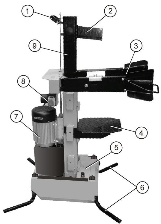
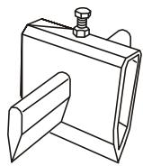
Unit description (Illus. A)
1 Transportation handle
2 Splitting blade
3 Control arms with levers and hand guards
4 Splitting table
5 Hydraulic oil tank
6 Stand feet
7 Motor
8 Switch/Plug socket combination
9 Splitter column
10 Swivel table
11 Engaging lever on swivel table
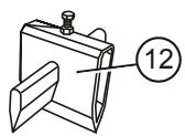
12 Splitting cross
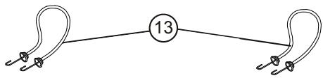
13 Securing rubber bands
Unpacking/Assembly

Caution!
The log splitter should only be used when all its component parts have been completely assembled.
- Check the package contents (Illus. A). Inform the dealer if deficiencies are detected.

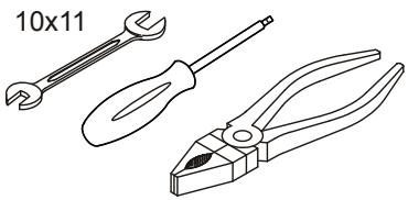
Note:
Tools required for assembly are depicted in Illus. C. These are not included in the scope of delivery.
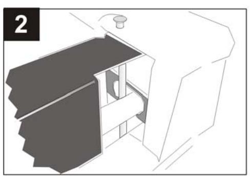
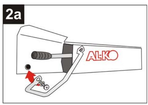
Mounting the control arms
- Grease the control arm bearing position top and bottom (Illus. 2).
- Insert the control arm and tube in the transverse connection recess (Illus. 2).
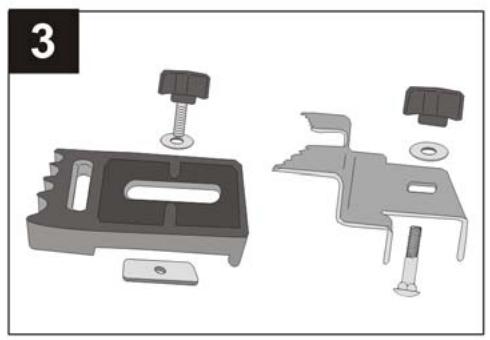
- Insert the retaining pin from above past the tube to the left and secure below with the washer and split pin (Illus. 3).
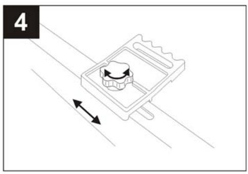
Adjusting the retaining claws
The retaining claws can be adjusted to suit the diameter of the timber. They should be set to the same dimension on both sides.
- Loosen the star grip on the retaining claw and adjust longitudinally to suit the timber diameter (Illus. 4).
- Tighten the star grip firmly again.
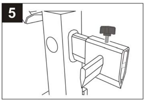
Mounting the splitting cross
- Screw the fixing screw (Illus. 5-1) somewhat into the splitting cross.
- Mount the splitting cross and screw the fixing screw into the recess in the splitting blade to draw the splitting cross upwards completely.
- Secure in the end position with the locking nut (Illus. 5-2).
Mains connection
The power supply is established via a switch/plug socket combination (Illus. A-8).
The switch is fitted with an integrated undervoltage release. This prevents the motor from starting again spontaneously in the event of a power cut. The motor can only be restarted by pressing the green activation button.
- Plug the connection cable into the unit.
- Connect the cable to the mains supply.

Note:
Check the direction of rotation of the motor in the case of a log splitter with a three-phase current motor (LHS 7000). The direction of rotation should correspond to the arrow on the fan cover. A polarity reversal should be realised in the plug with the phase inverter if this is not the case.

Warning!
An incorrect direction of rotation will damage the hydraulic pump.
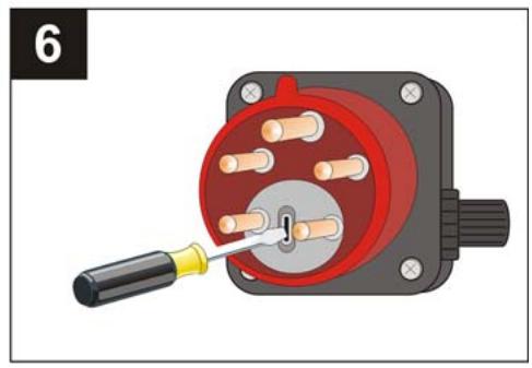
Plug polarity reversal
- Press in the phase inverter in the plug with a straight screwdriver and turn through 90^ (see Illus. 6).
- Establish the power supply and check the direction of rotation of the motor again.
Operation

Caution!
The log splitter should not be operated if components (e.g. the protective hoops) are missing or defective or the connection cable is damaged.
Prior to every use
- Conduct a visual inspection of the log splitter.
- The log splitter should not be operated if components are missing, defective or loose.
- Visually inspect the connection cable. A defective connection cable (e.g. with cracks, cuts, crushing damage or bends in the insulation) should not be used.
- Visually inspect the hydraulic components for leaks.
Log splitter start-up

Caution!
The log splitter should only be used by one person.
- Position the log splitter horizontally on a level, firm surface.
Do not deposit the log splitter on the connection cable! - Lay the connection cable so that it cannot be damaged by bending, crushing or otherwise.
-
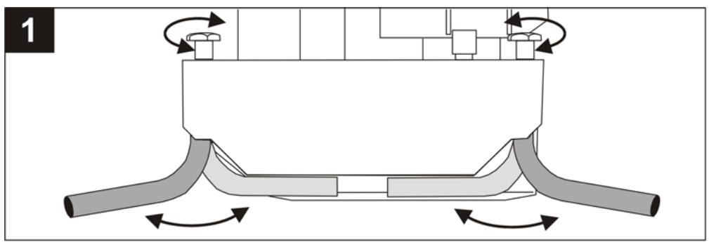
Loosen the star grips from the housing, unfold the feet outwards, securing them with the star grips.
-
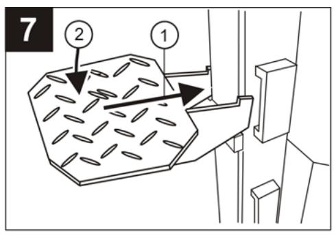
Set the splitting table at the level of the timber to be split (see Illus. 7). The splitting table should engage securely and be horizontal.
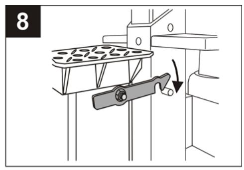
- In the case of the LHS 6000, LHS 7000 model, the swivel table can be swivelled inwards or outwards. The table has to be secured with the engaging lever when swivelled inwards (see Illus. 8).

Warning!
The splitting column moves automatically to the upper end position when the motor is switched on if the column is in the lowermost end position.
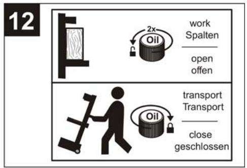
- Unscrew the oil inspection rod by 2 turns.
- Switch on the motor by pressing the green activation button.
- Adjust the splitting column stroke if necessary (see Stroke limitation).
- Position the piece of timber on the splitting table and secure with the retaining claws.
- Press both control levers downwards. The splitting process commences.
- Raise both control levers when the splitting process is completed to allow the splitting column to move upwards.

Caution!
The split timber should only be removed from the splitting table when the splitting column is in the upper end position.

Note:
Grease the splitting blade lightly when splitting extremely tough timber.
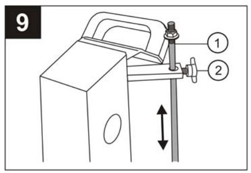
Stroke limitation
- Position a piece of timber on the splitting table.
- Press both control levers and move the splitting blade until it approaches to within 2 cm.
- Release one control lever and switch off the motor. The splitting blade remains stationary in this position.
- Release the fixing screw (Illus. 9-2), draw the stroke rod (Illus. 9-1) completely upwards and tighten the fixing screw firmly.
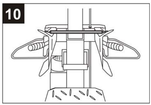
Transportation
- Move the splitting blade completely downwards and switch off the motor.

Caution!
Pull out the unit plug prior to every change of location.

Warning!
The oil inspection rod must be screwed firmly if the log splitter is to be transported, as hydraulic oil will otherwise leak out.
- Loosen the star grip on stand feet then fold the feet inwards and secure with a star grip.
- Secure both the control levers at the front with a rubber band (see Illus. 10).
- Tilt the splitter slightly to the rear with the hoop on the splitting column until the wheels are resting on the ground. The log splitter can be easily transported in this position.
Maintenance and care

Caution!
Switch off the log splitter and disconnect from the mains power supply prior to each working operation with the log splitter. Repairs to the log splitter should only be realised by a specialist firm or workshop.
Caring for the log splitter
Lubricating the splitting column
- The splitting column should be lubricated with grease free of resin or acid before every use. This increases the service life of the sliding jaws.
Maintenance work
Sharpening the splitting wedge
- The splitting wedge should be sharpened with a suitable file if necessary.
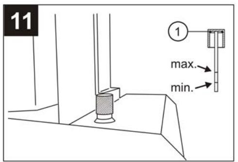
Checking the hydraulic oil filling level

Note:
Always check the hydraulic oil when the splitting column is moved inwards. The log splitter should be in a horizontal position.
- Unscrew the oil inspection rod and wipe with a clean, lint-free cloth.
-
Insert the oil inspection rod (do not screw it in) and pull out again. The oil level should be between the markings "min" and "max" (see Illus. 11). Top up the hydraulic oil if necessary.
-
Check the seals (Illus. 11-1) for damage and replace if necessary.

Warning!
Refill only with viscosity class HLP 46
hydraulic oil.
An oil change is not necessary.
Malfunctions
Switch off the log splitter and pull out the mains power plug in the event of malfunctions occurring. Engage a specialist firm or workshop to remedy malfunctions that cannot be rectified on the basis of the following table.
| Malfunction | Cause | Remedy |
| The splitting column does not move out/in | Motor rotation direction is incorrect (in case of LHS 7000) | Check direction of rotation |
| Too little hydraulic oil | Top up hydraulic oil | |
| The splitting blade does not exert any force | Too little hydraulic oil | Top up hydraulic oil |
| Trigger rod is bent | Have checked by specialist workshop | |
| Motor does not start | Thermostatic switch has tripped | Wait until the motor has cooled down. |
| The mains plug or socket is defective | Have checked by electrical spec- cialist | |
| Cable defective | Replace | |
| Hydraulic pump makes a whistling noise, the split- ting column moves with a jerking motion | Too little hydraulic oil | Top up hydraulic oil |
| The green activation button does not engage after pressing | No neutral conductor connected | Have cable and electrical power mains checked by electrical specialist |
| Defective fuse (only in case of LHS 7000) | ||
| A phase is missing (only in case of LHS 7000) | Have cable checked by electrical specialist | |
| Switch is defective | Replace | |
| Motor becomes exces-sively hot | Cable cross section is too small | Use cable with larger cross section |
| A phase is missing (only in case of LHS 7000) | Have cable and electrical power mains checked by electrical specialist |
Environmental protection, disposal

Do not dispose of old units in household waste!
The packaging, unit and accessories are made of materials that can be recycled and should be disposed of in a suitable manner.
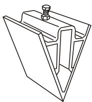
Accessories
See Illus. B for available accessories for all log splitters.
Hn B Koem cnyuae He npikacatbca K DvNkUyIeMycr KInHy.
Haunha 3KnIpyatauIO npOBOKoMa MoKHO NCKHouHTeJIbHO B TOM Cnyae,ecn OH NpOHCTbO CMOnTHnpOBaH, n ECNI DpOBOKoN IN pOBOD NITAHNA NOHOCtBIO NCnPABHbl.
3aMeHy NOBpeKDeHHbIX 3aUHTbIX yCTpoiCTB MOKeT PPOBOITb NCKIIOHTeJIbHO CNeUHaIN3HpOBaHHe OpeDnPnTne.
IcnoJIb3ObaTb NCKIOHTeJIbHO opINHaJIbHbIe 3anachble deTann.
OTKJIIOHTb DPOBOKOJ OT CETn pnp:
paobotax no TexHnueckomy o6cnykBaHHIO;
pa6oTax no HaJaIaKe;
TpaHcnpOpTnpOBKe;
KopoTKnX npepebIbax B paOte.
PemOH TpOBOKoJa MoKET BbIOnJIHrTb NcKJIHOuHTeIbHo CneuaJIn3nPoBaHHoe PpeIpnIaTne.
He octabJrTb roTOBbI K pa6Ote npOBOKoN 6e3 npuCMToPa.
He hauhnaTb pa60Tu C dpoBokonom, ecIn B6Jn-3n HaxoJrTcnoCTOpOHne JIua.
He 3KcnIpyAtnpoBaTb DpOBoKoN Bo BpeM DoJx, He OCTaBnTb NOD DoXdEm N He 06pbI3rBaTb BDOJ. OnachocTb 3JIeKtprueckoro yDapa.
Bpa6oey 3OHe IpoBOKOHa 3aIpeuaetc HaxoINTBcnoCTOpOHm INzam.CneINb, YTObbl B onaCHO 3OHe He 6bIIO DeTei N XNBOThbIX.
OnepaTop MaunHbI HeCet OTBETCTBeHHOCTb 3a 6e3oNaCHOCTb Dpyrnx IIOJeN COxpaHHOCtB IN mMyuiceTBA.
YdaIHTb n3 pa6oey 30Hb 6peBHa nIIN dpyRnne npedMeTb, YTObI He cNOTKHyTbCra.
3aunthbyeyctpoicTba
3aunthbainbTOMAT 3neKtpoDBurataeI
YcTaHOBkaФNKCuPyHouX3aXmOB npOn3BO-DITcB 3aBnCmOCTN OT dNaMeTp a6peBa.3aXmbl DOpKhbl 6bItb OndHaKOBO yCTaHOBHeblc o6eNx CTOpOH.
- Ocna6ntb 3Be3do06pa3Hyo pyko8Tky HaФнксуpoшem 3aximeи yCTaHOBtB 3aJxIM B pOdoJIbHOM nIonepeuHOM HappaBLeHn COOTBeTCTBeHHO dmaMeTpу 6peBHa (pnc.4).
- Choba 3aTaryb 3Be3Doo6pa3Hyu pyKoTky.
MOHTAX KpceTOBnHbI
- CnErKa BkpyTntb ΦnKcnpyUoIuBnBnHT (pnc. 5-1) B KpeCTOBnHy.
- BCTaBnTb KpeCTOBHHy n BkpyTnTb φnKcnyuOuIi BNHT B OTBepCTne BpackJIINHBAIOUe Hoxe, YTObI NODHrTb KpeCTOBHHy Do KOHca BBepx.
- 3aKpeINITb KpctOBHy B KOHeuHOM NIOJKeHnKoHTprAkoi(pnc.5-2).
THe3do NOdKJIIOUeHnK CcTeN
Iodaya nItaHnK MaunHe OcyuIeCTBnaTeTcNocpeDCTBOM KOMbHaCn BBIKNoUaTeJIy uTencelra (pnc.A-8).
BbIKIyOaTeNb OcHaSeH yCTpoiCTBOM OTKJIIOyeH NcENn npn nCue3HOBeHN HAnpJxKeH.N. OHO npEoTbPaUaet CamoCToRteNBbI 3anyck 3JeKToDBuRatJI NOcne npepbBaHN NOdaH ToKa. 3JeKToDBrAteJI 3anyckaETcA 3aHOBO hXaTHeM 3eHEny PnyCKOBK KNOKN.
- POnCoeAnHnTb npoBOd nHTaHnK MaunHe.
- BkHouHTb npoBOID nHTaHnB Cetb.

Yka3aHue:
Ydpokona cmpexpazhblm deuaamem (LHS 7000) npoeepumb hanaeeneue epaunna deuaamena. OH donxhen epaumbocn no cpmelke Ha kpbuikce eehmunnapa. Ecnu 3mozo He npucxodum, Heo6xoDUM nepekniouumb nonka Ha umencene, uonlb3yq fa3oebi KOMMymamop.

BhumaHue!
Bcneocmeue HnnpaunbHzo Hnpaenu epaueHnaeuaamena 6ydem noepexden uudpaanueckn Haoc.
Ipeeknuehen noIOcoB wTeNCen
- HaxaTb Ha φa3ObBiy KOMMyTaTOP ΜτeNceIa ΜλιηεBoI ΟΤΒeρΤΚΟΙ έΝΟΒeρΗΤb εο Ḁ 90°, cm. pnc. 6.
- PoiKJIIOUHTb 3JIeKTPoINITaHne I npOBepNTb HappaBHeHne BpaUeHnI 3JIeKTPoDIBrAteTJe.
3Kcnnyataun

Ocmopokxo!
3Kcnnyamaua npoeokona pa3pewa emc monbko cnyae, ecnu cce demaru (hnp. npdoxpanumenbbl konnak) ycmahoenehl Ha Mecmu u ucpnabHb, a npoeod numaHue He noepexdeH.
Ipeed kaxdbim nCNoJb3OBAHneM
Antonio De Filippo, Managing Director
Garantie
EC declaration of conformity
We hereby declare that this product, in the form in which it is marketed, meets the requirements of the harmonised EU guidelines, EU safety standards, and the product-specific standards.
Product
Log splitter
Serial number
G4064065
Model
LHS 5500
LHS 6000
LHS 7000
Sound power level
measured / guaranteed
86/88 dB(A)
Manufacturer
AL-KO Geräte GmbH
Ichenhauser Str. 14
89359 KOETZ
DEUTSCHLAND
EU directives
2006/42/EG (2009-12-29...)
2006/95/EG
2004/108/EG
2000/14/EG (13)
Conformity evaluation
2000/14/EG
Appendix VI
Executive Officer
Anton Eberle
Ichenhauser Str. 14
89359 KOETZ
DEUTSCHLAND
Harmonised standards
EN 60335-1;VDE 0700-1:2007-02
EN 60204-1;VDE 0113-1:2007-06
EN 60204-1/A1; VDE 0113-1/A1:2008-01
EN 609-1:1999-05
EN 609-1/A1:2004-05
EN 609-1/A2:2008-04
Kotz, 2010-02-03

Antonio De Filippo, Managing Director
Warranty
If any material or manufacturing defects are found during the statutory customer protection period, we will either repair or replace the equipment, whichever we consider the more appropriate. This statutory period may vary according to the legislation in force in the country where the equipment was purchased.
Our warranty is valid only if:
The equipment has been used properly
The operating instructions have been followed
Genuine replacement parts have been used
The warranty is no longer valid if:
The equipment has been tampered with
Technical modifications have been made
The trimmer was not used for its intended purpose (for example, used for commercial or communal applications)
The following are not covered by warranty:
Paint damage due to normal wear
Wear parts identified by a border [XXX XXX (X)] on the spare parts list
Combustion motors - these are covered by a separate warranty from the manufacturer concerned
To make a claim under warranty, please take this statement of warranty and proof of purchase to the nearest authorised customer service centre. This warranty does not affect the usual statutory rights of the customer relative to the seller.
Antonio De Filippo, Managing Director
Garantie
Antonio De Filippo, Managing Director
Garanzia
Antonio De Filippo, Managing Director
Garantie
Antonio De Filippo, Managing Director
Garantia
Antonio De Filippo, Managing Director
Garancia
Antonio De Filippo, Managing Director
Gwarancja
Antonio De Filippo, Managing Director
Záruka
Antonio De Filippo, Managing Director
Záruka
Antonio De Filippo, Managing Director
Fapantna
Mbyrotoby yctpaHnltb HeKOTOpBie NOrpeuHocTm MaTePnana IIN N3rOToBnEHHa B TeueHne YCTaHOBnEHORo 3akoHcpoKa daBHOCTn npdeJbAeHnI npTeH3nnIO KauchETBy (nytem peMOHTa INN 3aMeHb - no HaJeMy ycmOTpeHnO). CpOK daBHOCTn onpeDeneTc 3aKOHODaTeJIbCTBOM cTpaHb, rge 6bl KynIe HNCTpyMeNT.
Haun rapaHTnHbIe oBa3aTeNbCTBa DeiCTBnTeNbHbToJIbKO B cIeJyUxN cIyuaX:
TapaHTy TepaTeCnIy B CneDyUOuXx CnUyAax:
Pn nadnexkaem obaeHn C nHCTpyMeHTOM
Pnco6JIIODeHmpykoB0dCTBaNo3KcnnyatauHm
PnI NcNoJIb3OBAHmOprInHaJIbHbIX 3aNaChbIX TaCTeI
PnnoBtke noHHnHb HNCTpyMeHT
PnBHeCHeHm3MeHEnH B KOHCTpyKlIIO HNCTpyMeHTa
PnHnHaIeKaIeM IcNIOb3OBAHmN HcTpyMeHTa (HaIPIMep, B IpomblJeHHbIX ININ KOMMyHaJIbHbIX cJIeJx)
TapaHTnHe paCnPoCTpaHAreTcHa:
IIOBpeXeHnJaKOBOro NOKpbITnR, BO3HNKUnne No npuHHe HOpMaJIbHOrO n3HOca
I3haunbaeMbIe DetanI,OTmeueHHbIe paMKoX XXX XXX (X)Ha KapTe 3aNaChbIX YaCTei
Bniratenei BHytpenHero CrotapnHa-Ha Hnx paacnpocpaHcyoTcra OTeHbIe rapaHTmHbIe 63aTeIbCTBa COOTBETCTByIOUe IPOUN3BOIDNTeIa DBniratenei
B cnlyaee, Tpe6yuoIeM npdeocbaIeHnra paaHTnn, noKanayctA, oBaTInTeCb C daHbIM rapaHTmHbIM nMcBOM nekOM, noTBeRJaDIOUM NOKnyk, K BaSeMy dInepy mN B 6JnxKaIuN ABTOp3OBAHHb CEbpNCbIeHTP. JaHbIe rapaHTnBE O63aIbCTBa He paacnpoCTpaHryTcA OKOHm npdEBAHnna NokypaTeIeM npTeH3n I NO KaueCTBy K npOabuy.
EG-forsakran om overensstammelse
Antonio De Filippo, Managing Director
Garanti
Antonio De Filippo, Managing Director
Takuu
Antonio De Filippo, Managing Director
Garanti
2000/14/EG tillegg VI
Kotz, 2010-02-03

Antonio De Filippo, Managing Director
Garanti
Antonio De Filippo, Managing Director
Garantie
Antonio De Filippo, Managing Director
Garancija
Antonio De Filippo, Managing Director
Jamstvo
Eventualne greške na materijalu ili greške pri proizvodnji koje se pojavne na uredaju otklanjamo za vrijeme zakonskog jamstvenog roka za zahtjeve u slučaju nedostatak po našem izboru u vidu popravke ili zamjenske isporuke. Jamstveni rok odreduje se prema zakonu zemlje u kojoj je uredaj kuplejen.
- HOLZSPALTER
- LHS 5500 / LHS 6000 / LHS 7000
- Sicherheitshinweise
- Symbols
- On the unit
- Warning!
- In this operating manual
- Caution!
- Note:
- General safety instructions
- Safety measures
- Safety equipment
- Motor circuit breaker
- Connection cable
- Electrical requirements:
- LHS 5500, LHS 6000 models
- LHS 7000 model
- Correct use
- Incorrect use
- Unit description (Illus. A)
- Unpacking/Assembly
- Mounting the control arms
- Adjusting the retaining claws
- Mounting the splitting cross
- Mains connection
- Plug polarity reversal
- Operation
- Prior to every use
- Log splitter start-up
- Stroke limitation
- Transportation
- Maintenance and care
- Caring for the log splitter
- Lubricating the splitting column
- Maintenance work
- Sharpening the splitting wedge
- Checking the hydraulic oil filling level
- Malfunctions
- Environmental protection, disposal
- Accessories
- 3aunthbyeyctpoicTba
- 3aunthbainbTOMAT 3neKtpoDBurataeI
- MOHTAX KpceTOBnHbI
- THe3do NOdKJIIOUeHnK CcTeN
- Yka3aHue:
- BhumaHue!
- Ipeeknuehen noIOcoB wTeNCen
- 3Kcnnyataun
- Ocmopokxo!
- Ipeed kaxdbim nCNoJb3OBAHneM
- Garantie
- EC declaration of conformity
- Product
- Serial number
- Model
- Sound power level
- Manufacturer
- EU directives
- Conformity evaluation
- Executive Officer
- Harmonised standards
- Warranty
- Garanzia
- Garantia
- Garancia
- Gwarancja
- Záruka
- Fapantna
- EG-forsakran om overensstammelse
- Garanti
- Takuu
- Garancija
- Jamstvo
Brand : AL-KO
Model : LHS5500
Category : Log splitter