
GRL 300 HVG Professional - Rangefinder BOSCH - Free user manual and instructions
Find the device manual for free GRL 300 HVG Professional BOSCH in PDF.


| Product type | Professional rotary laser level |
| Brand | Bosch |
| Model | GRL 300 HVG Professional |
| Range | Up to 300 meters with receiver |
| Accuracy | ± 0.1 mm/m |
| Self-leveling | Self-leveling range ± 5°, electronic compensation |
| Rotation speed | 0, 150, 300, 600 rpm |
| Weight | Approx. 1.6 kg (with batteries) |
| Dimensions (L × W × H) | 14 × 14 × 22 cm |
| Power supply | 4 AA batteries (LR6) or mains power adapter (optional) |
| Battery life | Up to 30 hours (rotation mode) |
| Main functions | Rotation, line, plumb, slope, pulse |
| Protection rating | IP54 (protection against water splashes and dust) |
| Operating temperature | -10 °C to +50 °C |
| Included support | Tripod adapter 5/8 inch |
| Compatible receiver | LR 60 Professional (optional) |
| Maintenance and cleaning | Clean the lenses with a soft cloth; do not use solvents |
| Safety | Class 2 laser (visible); avoid direct eye contact |
| Spare parts and repairability | Bosch after-sales service; parts available through authorized network |
Frequently Asked Questions - GRL 300 HVG Professional BOSCH
User questions about GRL 300 HVG Professional BOSCH
0 question about this device. Answer the ones you know or ask your own.
Ask a new question about this device
Download the instructions for your Rangefinder in PDF format for free! Find your manual GRL 300 HVG Professional - BOSCH and take your electronic device back in hand. On this page are published all the documents necessary for the use of your device. GRL 300 HVG Professional by BOSCH.
USER MANUAL GRL 300 HVG Professional BOSCH
natural_image
3D rendering of a Bosch radar or surveying instrument with control knobs and a central dial (no visible text or symbols)Robert Bosch GmbH
Power Tools Division
70745 Leinfelden-Echterdingen
Germany
www.bosch-pt.com
2 610 A12 916 (2010.03) T / 470 XXX

GRL Professional
250 HV | 300 HV | 300 HVG

BOSCH
natural_image
Technical diagram of a Bosch lift sensor mounted on a metal frame structure (no text or symbols visible)
natural_image
Interior view of a room with two surveying equipment and a tripod-mounted camera, no visible text or symbols

natural_image
Architectural 3D rendering of a modular building facade with diagonal bracing and window (no text or symbols)
natural_image
Diagram of a surveying instrument mounted on a tripod in a room, with no visible text or symbols
natural_image
Isometric architectural diagram of a room with structural beams and columns, no text or symbols present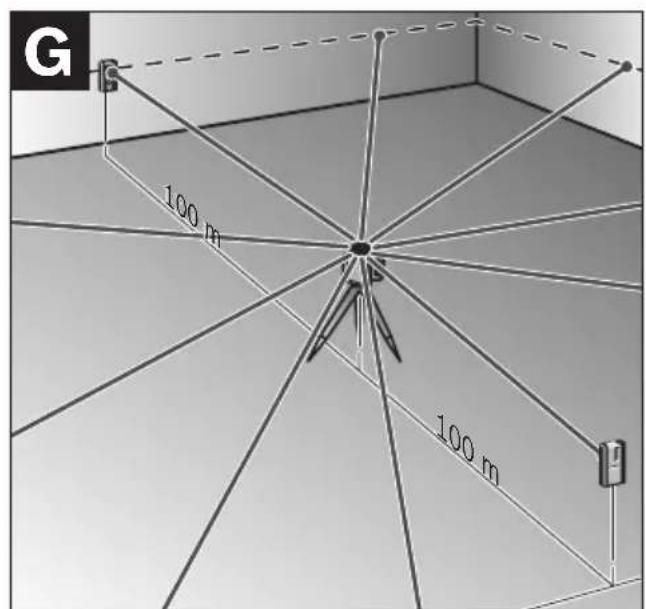

natural_image
Interior view of a room with a camera setup and measurement equipment (no visible text or symbols)

Sicherheitshinweise
Rotationslaser

Dr. Egbert Schneider Senior Vice President Engineering
Dr. Eckerhard Strötgen Head of Product Certification
ppa. A##u i.v. NuOyen
Robert Bosch GmbH, Power Tools Division D-70745 Leinfelden-Echterdingen Leinfelden, 04.03.2010
Montage
natural_image
Technical line drawing of a mechanical component with no visible text or symbolsVertikallage
natural_image
Technical line drawing of a mechanical device with no visible text or symbolsRotationsbetrieb
natural_image
Technical line drawing of a mechanical device with no visible text or symbolsLinienbetrieb
natural_image
Technical line drawing of a mechanical device with no visible text or symbolsPunktbetrieb
Rotational Laser Level

Working safely with the measuring tool is possible only when the operating and safety information are read completely and the instructions contained therein are strictly followed. Never make warning labels on the measuring tool unrecognisable. SAVE THESE INSTRUCTIONS.
- Caution – The use of other operating or adjusting equipment or the application of other processing methods than those mentioned here, can lead to dangerous radiation exposure.
▶ Do not use the laser viewing glasses as safety goggles. The laser viewing glasses are used for improved visualisation of the laser beam, but they do not protect against laser radiation.
▶ Do not use the laser viewing glasses as sun glasses or in traffic. The laser viewing glasses do not afford complete UV protection and reduce colour perception.
▶ Have the measuring tool repaired only through qualified specialists using original spare parts. This ensures that the safety of the measuring tool is maintained.
▶ Do not operate the measuring tool in explosive environments, such as in the presence of flammable liquids, gases or dusts. Sparks can be created in the measuring tool which may ignite the dust or fumes.
▶ Do not open the battery pack. Danger of short-circuiting.
Protect the battery pack against heat, e.g., against continuous intense sunlight, fire, water, and moisture. Danger of explosion.
- Keep the battery pack not being used away from paper clips, coins, keys, nails, screws or other small metal objects that can make a connection from one terminal to another. Shorting the battery terminals together may cause burns or a fire.
▶ Charge the battery pack only with the battery charger specified in these operating instructions. A charger that is suitable for one type of battery pack may create a risk of fire when used with another battery pack.
▶ Use only original Bosch battery packs with the voltage listed on the nameplate of your measuring tool. When using other battery packs, e.g. imitations, reconditioned battery packs or other brands, there is danger of injury as well as property damage through exploding battery packs.

GRL 250 HV/GRL 300 HV
The measuring tool is provided with a warning label in English (marked with number 20 in the representation of the measuring tool on the graphics page).

▶ Do not direct the laser beam at persons or animals and do not stare into the laser beam yourself. This measuring tool produces laser class 2 laser radiation according to IEC 60825-1. This can lead to persons being blinded.
▶ Do not allow children to use the laser measuring tool without supervision. They could unintentionally blind other persons or themselves.
GRL 300 HVG
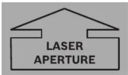
The measuring tool is provided with two warning labels in English (marked with number 20 and 21 in the representation of the measuring tool on the graphics page).
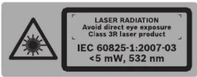
- Do not direct the laser beam at persons or animals and do not look into the laser beam yourself. This measuring tool generates laser radiation from class 3R according to IEC 60825-1. Looking directly into the laser beam – even from a greater distance cause damages to the eyes.
- Avoid reflection of the laser beam on smooth surfaces such as windows or mirrors. A reflected laser beam can also cause damage to the eye.
The measuring tool should be operated only by persons that are familiar with the handling of laser devices. According to EN 60825-1, this includes, among other things, the knowledge about the biological effects of the laser to the eyes and the skin as well as the correct usage of laser protection devices in order to avoid dangers.
▶ Always set up the measuring tool in such a manner that the laser beams run far above or below eye level. This ensures that damage to the eyes will not occur.
▶ Mark the area in which the measuring tool is being used with suitable laser warning labels. This prevents persons not involved from accessing the danger area.
▶ Do not store the measuring tool at locations, to which unauthorised persons have access. Persons not familiar with the operation of the measuring tool can cause harm to themselves and to others.
When using a class 3R measuring tool, observe possible national regulations. Non-observance of these regulations can lead to injury.
▶ Make sure that the area of laser radiation is monitored or shielded. The limitation of laser radiation to controlled areas prevents eye damage to persons not involved.
Battery Charger

Read all safety warnings and all instructions. Failure to follow the warnings and instructions may result in electric shock, fire and/or serious injury.

Keep the battery charger away from rain or moisture. Penetration of water in the battery charger increases the risk of an electric shock.
▶ Do not charge other batteries with the battery charger. The battery charger is only suitable for charging the Bosch battery/battery pack inserted in the rotational laser level. Danger of fire and explosion when charging other batteries/battery packs.
▶ Keep the battery charger clean. Contamination can lead to danger of an electric shock.
Before each use, check the battery charger, cable and plug. If damage is detected, do not use the battery charger. Never open the battery charger yourself. Have repairs performed only by a qualified technician and only using original spare parts. Damaged battery chargers, cables and plugs increase the risk of an electric shock.
▶ Do not operate the battery charger on easily inflammable surfaces (e.g., paper, textiles, etc.) or surroundings. The heating of the battery charger during the charging process can pose a fire hazard.
▶ Under abusive conditions, liquid may be ejected from the battery; avoid contact. If contact accidentally occurs, flush with water. If liquid contacts eyes, additionally seek medical help. Liquid ejected from the battery may cause irritations or burns.
▶ Children should be supervised to ensure that they do not play with the battery charger.
▶ Products sold in GB only: Your product is fitted with an BS 1363/A approved electric plug with internal fuse (ASTA approved to BS 1362).
If the plug is not suitable for your socket outlets, it should be cut off and an appropriate plug fitted in its place by an authorised customer service agent. The replacement plug should have the same fuse rating as the original plug.
The severed plug must be disposed of to avoid a possible shock hazard and should never be inserted into a mains socket elsewhere.
Functional Description
While reading the operating instructions, unfold the graphics page with the illustration of the rotational laser level and battery charger, and leave it open.
Intended Use
Rotational Laser Level
The measuring tool is intended for determining and checking precise horizontal partitions, vertical lines, building lines and plumb points.
The measuring tool is suitable for indoor and outdoor use.
Battery Charger
Use the battery charger only when you fully understand and can perform all functions without limitation, or have received appropriate instructions.
Technical Data
| Rotational Laser Level GRL 250 HV | GRL 300 HV Professional | GRL 300 HVG Professional | |
| Professional | |||
| Article number | 3 601 K61 60. | 3 601 K61 50. | 3 601 K61 70. |
| Working range (radius)1)– without laser receiver, approx.– with laser receiver, approx. | 30 m125 m | 30 m150 m | 50 m150 m |
| Levelling Accuracy1) 2) | ±0.1 mm/m | ±0.1 mm/m | ±0.1 mm/m |
| Self-levelling range, typically | ±8 % (±5°) | ±8 % (±5°) | ±8 % (±5°) |
| Levelling duration, typically | 15 s | 15 s 15 s | |
| Rotational speed | 150/300/600 min-1 | 150/300/600 min-1 | 150/300/600 min-1 |
| Aperture angle for line operation 10/25/50° 10/25/50° | 10/25/50° | ||
| Operating temperature | -10 ... +50 °C | -10 ... +50 °C | 0 ... +40 °C |
| Storage temperature | -20 ... +70 °C | -20 ... +70 °C | -20 ... +70 °C |
| Relative air humidity, max. | 90 % | 90 % 90 % | |
| Laser class | 2 | 2 | 3R |
| Laser type | 635 nm, <1 mW | 635 nm, <1 mW | 532 nm, <5 mW |
| Laser beam ∅ at the exit opening, approx.1) | 5 m m | 5 m m | 5 m m |
| Tripod mount (horizontal) | 5/8"-11 | 5/8"-11 | 5/8"-11 |
| Batteries (NiMH) | 2 x 1 . 2 V H R 2 0(9 Ah) | (D2) x 1 . 2 V H R 2 0(9 Ah) | (D2) x 1.2 V HR20 (D)(9 Ah) |
| Batteries (alkali-manganese) | 2 x 1 . 5 V L R 2 0 | (D2) x 1 . 5 V L R 2 0 | (D2) x 1.5 V LR20 (D) |
| Operating life time, approx.– Batteries (NiMH)– Batteries (alkali-manganese) | 40 h60 h | 30 h50 h | 20 h30 h |
| Weight according to EPTA-Procedure 01/2003 | 1.8 kg | 1.8 kg | 1.8 kg |
| Dimensions | 190 x 180 x 170 mm | 190 x 180 x 170 mm | 190 x 180 x 170 mm |
| Degree of protection | IP 54 (dust and splash water pro-tected) | IP 54 (dust and splash water pro-tected) | IP 54 (dust and splash water pro-tected) |
1) at 20 °C
2) alongside the axes
Please observe the article number on the type plate of your measuring tool. The trade names of the individual measuring tools may vary.
The measuring tool can be clearly identified with the serial number 19 on the type plate.
| Battery Charger | ||
| Article number 2 610 A13 782 | ||
| Rated voltage | V~ 100–240 | |
| Frequency | Hz 50/60 | |
| Output voltage | V= 7.5 | |
| Charging current | A | 1.0 |
| Allowable charging temperature range | °C 0–45 | |
| Charging time | h | 14 |
| Number of battery cells | 2 | |
| Rated voltage (rechargeable batteries) | V= 2 x 1.2 | |
| Weight according to EPTA-Procedure 01/2003 | kg 0.2 | |
| Protection class | ☐/II | |
Product Features
The numbering of the product features refers to the illustration of the rotational laser level and battery charger on the graphics page.
1 Shock-warning indicator
2 Shock-warning button
3 Automatic levelling indicator
4 On/Off button of the rotational laser level
5 Button for rotational operation and selection of the rotation speed
6 Variable laser beam
7 Reception lens for remote control
8 Exit opening for laser beam
9 Plumb beam
10 Rotation head
11 Button for line operation and line length selection
12 Charge-control indicator
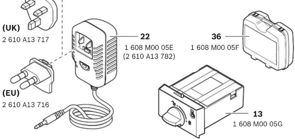
13 Battery pack*
14 Battery compartment
15 Locking knob of the battery compartment
16 Locking knob of the battery pack*
17 Socket for charge plug*
18 Tripod mount 5/8"
19 Serial number
20 Laser warning label
21 Warning label, laser radiation exit opening (GRL 300 HVG)
22 Battery charger*
23 Mains plug of the battery charger*
24 Charge connector*
25 Remote control*
26 Tripod*
27 Construction laser measuring rod*
28 Laser receiver*
29 Laser viewing glasses*
30 Wall mount/alignment unit*
31 Fastening screw of the wall mount*
32 Screw of the alignment unit*
33 5/8" screw on wall mount*
34 Measuring plate with stand*
35 Ceiling measurement plate*
36 Case
* The accessories illustrated or described are not included as standard delivery.
Noise Information
Rotational Laser Level
Measured sound values determined according to EN 60745.
Typically the A-weighted sound pressure level of the measuring tool is less than 70 dB(A).
Declaration of Conformity CE
We declare under our sole responsibility that the product described under “Technical Data” is in conformity with the following standards or standardization documents: EN 61010-1, EN 60825-1 (measurement tool) respectively EN 60950-1 (battery charger) according to the provisions of the directives 2006/95/EC, 2004/108/EC, 2006/42/EC.
Technical file at: Robert Bosch GmbH, PT/ESC, D-70745 Leinfelden-Echterdingen
CE 2010
Dr. Egbert Schneider Senior Vice President Engineering
Dr. Eckerhard Strötgen Head of Product Certification
ppa. A##u i.v. P#o#en
Robert Bosch GmbH, Power Tools Division D-70745 Leinfelden-Echterdingen Leinfelden, 04.03.2010
Assembly
Power Supply of the Rotational Laser Level
Operation with Batteries/Rechargeable Batteries
Using alkali-manganese or rechargeable batteries is recommended for operation of the measuring tool.
To open the battery compartment 14, turn the locking knob 15 to position and pull out the battery compartment.
When inserting batteries, pay attention to the correct polarity according to the representation on the inside of the battery compartment.
Always replace all batteries at the same time. Only use batteries from one brand and with the identical capacity.
Shut the battery compartment 14 and turn the locking knob 15 to the position.
In case the batteries have been inserted incorrectly, the measuring tool cannot be switched on. Insert the batteries with correct polarity.
Remove the batteries from the measuring tool when not using it for extended periods. When storing for extended periods, the batteries can corrode and discharge themselves.
Operation with Battery Pack
Charge the battery pack 13 before using for the first time. The battery pack can only be charged with the battery charger 22 intended for it.
▶ Observe the mains voltage! The voltage of the power supply must correspond with the data given on the nameplate of the battery charger. Battery chargers marked with 230 V can also be operated with 220 V.
Insert the appropriate mains plug 23 for your mains supply into the battery charger 22 and allow it to engage.
Insert the charge plug 24 of the battery charger into the socket connector 17 of the battery pack. Connect the battery charger to the mains supply. Charging the empty battery pack takes approx. 14 h. The battery charger and the battery pack are protected against overcharging.
A battery that is new or has not been used for a longer period does not develop its full capacity until after approx. 5 charging/discharging cycles.
Do not charge the battery pack 13 each time after using, otherwise its capacity will be reduced. Charge the battery pack only when the charge-control indicator 12 flashes or lights up continuously.
A considerably reduced operating period after charging indicates that the battery pack is used up and must be replaced.
If the battery pack is empty, the measuring tool can also be operated off of the battery charger 22 when connected to a power supply. Switch the measuring tool off, charge the battery pack for approx. 10 min and then switch the measuring tool on again with the battery charger connected.
To change the battery pack 13, turn the locking knob 16 to position and pull out the battery pack 13.
Insert a new battery pack and turn the locking knob 16 to the position.
Remove the battery pack from the measuring tool when not using it for longer periods. When storing for longer periods, the rechargeable batteries can corrode and discharge themselves.
Charge-control Indicator
When the charge-control indicator 12 flashes red for the first time, the measuring tool can still be operated for approx. 2 h.
When the charge-control indicator 12 lights up red continuously, measurements are no longer possible. The measuring tool switches off automatically after 1 minute.
Operation
Starting Operation of the Rotational Laser Level
▶ Protect the measuring tool against moisture and direct sun light.
Do not subject the measuring tool to extreme temperatures or variations in temperature. As an example, do not leave it in vehicles for longer periods. In case of large variations in temperature, allow the measuring tool to adjust to the ambient temperature before putting it into operation. In case of extreme temperatures or variations in temperature, the accuracy of the measuring tool can be impaired.
- Avoid heavy impact to or dropping down of the measuring tool. After severe exterior effects to the measuring tool, it is recommended to carry out an accuracy check (see “Levelling Accuracy of the Rotational Laser Level”, page 30) each time before continuing to work.
Setting Up the Measuring Tool

Horizontal position
Vertical position

natural_image
Technical line drawing of a mechanical device with no visible text or symbolsSet up the measuring tool on a sturdy surface in the horizontal or vertical position; mount it on a tripod 26 or to the wall mount with alignment unit 30.
Due to the high levelling accuracy, the measuring tool reacts sensitively to ground vibrations and position changes. Therefore, pay attention that the position of the measuring tool is stable in order to avoid operational interruptions due to re-levelling.
Switching On and Off
Do not direct the laser beam at persons or animals (especially not at their eye level), and do not stare into the laser beam yourself (not even from a distance). Immediately after switching on, the measuring tool sends out the vertical plumb beam 9 and the variable laser beam 6.
For switching on the measuring tool, press the On/Off button 4. The indicators 1, 3 and 12 light up briefly. The measuring tool immediately starts the automatic levelling. During the levelling, the levelling indicator 3 lights up green and the laser flashes in point operation.
The measuring tool is levelled in as soon as levelling indicator 3 lights up green continuously and the laser beam is steady. After the levelling is completed, the measuring tool automatically starts in rotational operation.
With the operating mode buttons 5 and 11, the operating modes can already be specified during levelling in (see “Operating Modes of the Rotational Laser Level”, page 29). In this case, the measuring tool starts in the set operating mode upon completion of levelling in.
To switch off the measuring tool, press the On/Off button 4 again.
▶ Do not leave the switched on measuring tool unattended and switch the measuring tool off after use. Other persons could be blinded by the laser beam.
To save the batteries, the measuring tool is automatically switched off when not within the self-levelling range for more than 2 h or when the shock warning is actuated for more than 2 h (see “Automatic Levelling of the Rotational Laser Level”, page 30). Reposition the measuring tool and switch it on again.
Operating Modes of the Rotational Laser Level
Overview
All three operating modes are possible with the measuring tool in horizontal and vertical position.
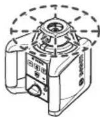
natural_image
Technical line drawing of a mechanical device with no visible text or symbolsRotational Operation
Rotational operation is especially recommended when using the laser receiver. You can select between different rotational speeds.

natural_image
Technical line drawing of a mechanical device with no visible text or symbolsLine Operation
In this operation mode, the variable laser beam moves within a limited aperture angle. This increases the visibility of the laser beam in comparison to rotational operation. You can select between different aperture angles.

natural_image
Technical line drawing of a mechanical device with no visible text or symbolsPoint Operation
This operation mode enables the best visibility of the variable laser beam. As an example, it is used for easy projecting of heights or checking building lines.

Rotational Operation (150/300/600 min -1 )
Each time after switching on, the measuring tool is in rotational operation mode with average rotational speed.
To switch from line operation to rotational operation, press the rotational operation button 5. Rotational operation starts with average rotational speed.
To change the rotational speed, press the rotational operation button 5 again until the requested speed is reached.
When working with the laser receiver, the highest rotational speed should be set. When working without laser receiver, reduce the rotational speed for improved visibility of the laser beam and use the laser viewing glasses 29.

Line Operation, Point Operation (10°/25°/50°, 0°)
To switch to line or point operation, press the line operation button 11. The measuring tool switches to line operation with the smallest aperture angle.
To change the aperture angle, press the line operation button 11. The aperture angle is increased in two steps; at the same time, the rotational speed is increased with each step. When pressing the line operation button 11 a third time, the measuring tool switches to point operation after brief post-pulsation. Pressing button 11 again takes you back to line operation with the smallest aperture angle.
Note: Due to inertia, it is possible for the laser to slightly move beyond the end point of the laser line.
To position the laser line or the laser point within the rotational plane, manually turn the rotation head 10 to the requested position or use the remote control 25.
Turning the Rotational Plane when in the Vertical Position
When the measuring tool is in the vertical position, it is possible to rotate the laser point, laser line or rotational plane around the vertical axis with help of the remote control 25. For this, observe the operating instructions of the remote control.
Automatic Levelling of the Rotational Laser Level
Overview
After switching on, the measuring tool automatically detects the horizontal or vertical position. To change between the horizontal and vertical position, switch the measuring tool off, reposition it and switch on again.
After switching on, the measuring tool checks the horizontal and vertical position and automatically levels out any unevenness within the self-levelling range of approx. 8 % (5°).
When the measuring tool is inclined by more than 8 % after switching on or after a position change, levelling in is no longer possible. In this case, the rotor is stopped, the laser flashes and levelling indicator 3 continuously lights up red. Reposition the measuring tool and wait for it to re-level. Without repositioning, the laser is automatically switched off after 2 minutes and the measuring tool after 2 hours.
When the measuring tool is levelled in, it continuously checks the horizontal and vertical position. Automatic re-levelling takes place after position changes. To avoid faulty measurements, the rotor stops during the levelling process, the laser flashes and the levelling indicator 3 flashes green.

Shock-warning Function
The measuring tool has a shock-warning function; after position changes or shock to the measuring tool, or in case of ground vibrations, it keeps the measuring tool from levelling in at changed heights, and thus prevents vertical errors.
To switch on the shock-warning function, press the shock-warning button 2. The shock-warning indicator 1 continuously lights up green, and the shock-warning function is activated after 30 seconds.
When the levelling-accuracy range is exceeded after a position change of the measuring tool or when heavy ground vibrations are detected, the shock-warning function is actuated: The rotation is stopped, the laser flashes, the levelling indicator 3 goes out and the shock-warning indicator 1 flashes red. The current operating mode is stored.
After the shock-warning function has actuated, press the shock-warning button 2. The shock-warning function is restarted and the measuring tool starts the levelling. As soon as the measuring tool is levelled in (levelling indicator 3 continuously lights up green), it starts in the stored operating mode. Now, check the height of the laser beam with a reference point and correct the height, if required.
When the function is not restarted by pressing button 2 after the shock-warning function has actuated, the laser is automatically switched off after 2 minutes and the measuring tool after 2 hours.
To switch off the shock-warning function, press shock-warning button 2 once, or, when the shock warning is actuated (shock-warning indicator 1 flashing red) press it twice. When the shock-warning function is shut off, the shock-warning indicator 1 goes out.
Levelling Accuracy of the Rotational Laser Level
Influences on Accuracy
The ambient temperature has the greatest influence. Especially temperature differences occurring from the ground upward can divert the laser beam.
The deviations play a role in excess of approx. 20 m measuring distance and can easily reach two to four times the deviation at 100 m.
Because the largest difference in temperature layers is close to the ground, the measuring tool should always be mounted on a tripod when measuring distances exceeding 20 m. If possible, also set up the measuring tool in the centre of the work area.
Accuracy Check of the Measuring Tool
Apart from exterior influences, device-specific influences (such as heavy impact or falling down) can lead to deviations. Therefore, check the accuracy of the measuring tool each time before starting your work.
For the accuracy check, an unobstructed measuring distance of 20 m on firm ground between two walls A and B is required. With the measuring tool in the horizontal position, a transit measurement is to be carried out across both axes X and Y (both positive and negative) (altogether 4 complete measurements).
- Mount the measuring tool in the horizontal position onto a tripod 26 (accessory) or place it on a firm and level surface near wall A. Switch the measuring tool on.
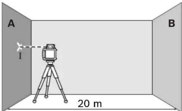
- After levelling, direct the laser beam in point operation onto the close wall A. Mark the centre point of the laser beam on the wall (point I).

- Turn the measuring tool around by 180irc , allow it to level in and mark the centre point of the laser beam on the opposite wall B (point II).
- Without turning the measuring tool, position it close to wall B. Switch the measuring tool on and allow it to level in.
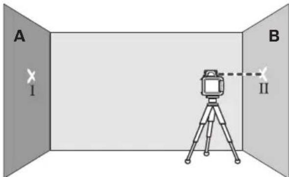
- Align the height of the measuring tool (using the tripod or by underlaying, if required) in such a manner that the centre point of the laser beam is projected exactly against the previously marked point II on wall B.
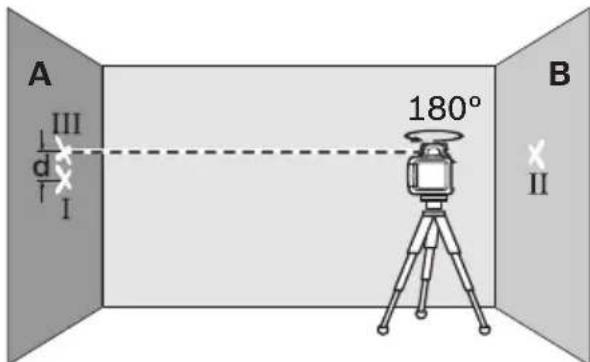
- Rotate the measuring tool by 180irc without changing the height. Allow it to level in and mark the centre point of the laser beam on wall A (point III). Take care that point III is as vertical as possible above or below point I.
- The difference d of both marked points I and III on wall A amounts to the actual deviation of the measuring tool for the measured axis.
Repeat the measuring procedure for the other three axes. For this, turn the measuring tool prior to each measuring procedure by 90°.
On the measuring section of 2 × 20 m = 40 m , the maximum allowable deviation is:
40 m x ±0.1 mm/m = ±4 mm.
Consequently, the difference d between points I and III for each of the four individual measurements may not exceed 4 mm max.
If the measuring tool should exceed the maximum deviation in anyone of the four measuring procedures, have it checked at a Bosch after-sales service agent.
Working Advice
▶ Always use the centre of the laser point for marking. The size of the laser point changes with the distance.
Laser Viewing Glasses (Accessory)
The laser viewing glasses filter out the ambient light. This makes the red light of the laser appear brighter for the eyes.
▶ Do not use the laser viewing glasses as safety goggles. The laser viewing glasses are used for improved visualisation of the laser beam, but they do not protect against laser radiation.
▶ Do not use the laser viewing glasses as sun glasses or in traffic. The laser viewing glasses do not afford complete UV protection and reduce colour perception.
Working with the Laser Receiver (Accessory)
Under unfavourable light conditions (bright environment, direct sunlight) and for larger distances, use the laser receiver for improved finding of the laser beam 28.
When working with the laser receiver, select rotational operation with the highest rotational speed.
Before working with the laser receiver, read and observe the laser receiver operating instructions.
Working with the Remote Control (Accessory)
While pressing the operator buttons, the measuring tool can be brought out of alignment so that the rotation is briefly stopped. This effect is avoided when using the remote control 25.
Reception lenses 7 for the remote control are located on three sides of the measuring tool, among other locations above the control panel on the front side.
Working with the Tripod (Accessory)
The measuring tool is equipped with a 5/8" tripod mount for horizontal operation on a tripod. Place the measuring tool via the tripod mount 18 onto the 5/8" male thread of the tripod and screw the locking screw of the tripod tight.
On a tripod 26 with a measuring scale on the elevator column, the height difference can be adjusted directly.
Working with Wall Mount/Alignment Unit (Accessory) (see figure A)
You can also mount the measuring tool to the wall mount with alignment unit 30. For this, screw the 5/8" screw 33 of the wall mount into the tripod mount 18 of the measuring tool.
Mounting to a wall: Mounting to a wall is recommended, e.g., for work above the elevation height of tripods or for work on unstable surfaces and without tripod. For this, fasten the wall mount 30, with the measuring tool mounted, as vertical as possible to a wall.
For mounting to the wall, you can either fasten the wall mount 30 with fastening screw 31 to a lath (width maximal 8 mm) or hang it up with two hooks.
Mounting on a tripod: The wall mount 30 can also be screwed onto a tripod with the tripod mount on the back side. This method of fastening is especially recommended for work where the rotational plane is to be aligned with a reference line.
With the alignment unit, the mounted measuring tool can be moved vertically (when mounted to the wall) or horizontally (when mounted to a tripod) within a range of approx. 16 cm. For this, loosen screw 32 on the alignment unit, move the measuring tool to the desired position, and retighten screw 32 again.
Working with the Ceiling Measurement Plate (see figure A)
As an example, the ceiling measurement plate 35 can be used for easy height adjustment of drop ceilings. Fasten the ceiling measurement plate with the magnetic holder, e.g., to a beam.
The reflecting half of the ceiling measurement plate improves the visibility of the laser beam in unfavourable conditions; the laser beam can also be seen from the rear side through the transparent half.
Working with the Measuring Plate (Accessory)
With the measuring plate 34, it is possible to project the laser mark onto the floor or the laser height onto a wall.

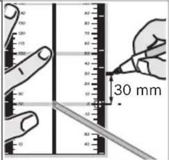
With the zero field and the scale, the offset or drop to the required height can be measured and projected at another location. This eliminates the necessity of precisely adjusting the measuring tool to the height to be projected.
The measuring plate 34 has a reflective coating that enhances the visibility of the laser beam at greater distances or in intense sunlight. The brightness intensification can be seen only when viewing, parallel to the laser beam, onto the measuring plate.
Working with the Measuring Rod (Accessory) (see figure H)
For checking irregularities or projecting gradients, it is recommended to use the measuring rod 27 together with the laser receiver.

A relative millimeter scale ( ±50 cm) is marked on the top of the measuring rod 27. Its zero height can be preset at the bottom of the elevator column. This allows for direct reading of deviations from the specified height.
Work Examples
Projecting/Checking Heights (see figure B)
Position the measuring tool in the horizontal position onto a firm support or mount it onto a tripod 26 (accessory).
Working with tripod: Align the laser beam to the requested height. Project or check the height at the target location.
Working without tripod: Determine the height difference between the laser beam and the height at the reference point with help of the measurement plate 34. Project or check the measured height difference at the target location.
Parallel Alignment of a Plumb Beam/Projecting Right Angles (see figure C)
When right angles are to be projected or when partitions are to be aligned, the plumb beam 9 must be aligned parallel, meaning at the same distance to a reference line (e.g. a wall).
For this, set up the measuring tool in the vertical position and position it in such a manner that the plumb beam runs approximately parallel to the reference line.
For exact positioning, measure the clearance between plumb beam and reference line directly on the measuring tool with help of the measurement plate 34. Measure the clearance between plumb beam and reference line again as far away as possible from the measuring tool. Align the plumb beam in such a manner that it has the same clearance to the reference line as when measured directly at the measuring tool.
The right angle to the plumb beam 9 is indicated by the variable laser beam 6.
Indicating a Plumb Line/Vertical Plane (see figure D)
To indicate a plumb line or a vertical plane, set up the measuring tool in the vertical position. When the vertical plane is supposed to run at a right angle to a reference line (e.g. a wall), then align the plumb beam 9 with this reference line. The plumb line is indicated by the variable laser beam 6.
Working without Laser Receiver (see figure E)
Under favourable light conditions (dark environment) and for short distances, it is possible to work without the laser receiver. For better visibility of the laser beam, either select line operation, or select point operation and manually rotate the rotation head 10 to the target location.
Working with the Laser Receiver (see figure F)
Under unfavourable light conditions (bright environment, direct sunlight) and for larger distances, use the laser receiver for improved finding of the laser beam. When working with the laser receiver, select rotational operation with the highest rotational speed.
Measuring Over Long Distances (see figure G)
When measuring over long distances, the laser receiver must be used to find the laser beam. In order to reduce interferences, the measuring tool should always be set up in the centre of the work surface and on a tripod.
Working Outdoors (see figure H)
The laser receiver should always be used when working outdoors.
When working on unstable ground, mount the measuring tool onto the tripod 26. Activate the shock-warning function in order to avoid faulty measurements in case of ground vibrations or shock to the measuring tool.
Overview of Indications
| Laser beam | Rotation of the laser* | green red green red | |
| Switching on the measuring tool (1 s self-check) ● | ● | ● | |
| Levelling in or re-levelling 2x/s ○ 2x/s | |||
| Measuring tool levelled in/ready for operation ● ● ● | |||
| Self-levelling range exceeded 2x/s ○ | ● | ||
| Shock-warning function activated ● | |||
| Shock warning actuated 2x/s ○ 2x/s | |||
| Battery voltage for ≤2 h operation | 2x/s | ||
| Battery empty ○ ○ | ● | ||
| * for line and rotational operation | |||
| 2x/s | Flashing frequency (twice per second) | ||
| ● | Continuous operation | ||
| ○ | Function stopped | ||
Maintenance and Service
Maintenance and Cleaning
Keep the rotational laser level and battery charger clean at all times.
Do not immerse the rotational laser level and battery charger into water or other fluids.
Wipe off debris using a moist and soft cloth. Do not use any cleaning agents or solvents.
Particularly clean the surfaces at the outlet opening of the rotational laser level regularly and pay attention for any lint.
If the rotational laser level or battery charger should fail despite the care taken in manufacture and testing, repair should be carried out by an authorised customer services agent for Bosch power tools. Do not open the rotational laser level and the battery charger yourself.
In all correspondence and spare parts orders, please always include the 10-digit article number given on the type plate of the rotational laser level and battery charger.
After-sales Service and Customer Assistance
Our after-sales service responds to your questions concerning maintenance and repair of your product as well as spare parts. Exploded views and information on spare parts can also be found under:
www.bosch-pt.com
Our customer service representatives can answer your questions concerning possible applications and adjustment of products and accessories.
Great Britain
Robert Bosch Ltd. (B.S.C.)
P.O. Box 98
Broadwater Park
North Orbital Road
Denham
Uxbridge
UB 9 5HJ
Tel. Service: +44 (0844) 736 0109
Fax: +44 (0844) 736 0146
E-Mail: boschservicecentre@bosch.com
Ireland
Origo Ltd.
Unit 23 Magna Drive
Magna Business Park
City West
Dublin 24
Tel. Service: +353 (01) 4 66 67 00
Fax: +353 (01) 4 66 68 88
Australia, New Zealand and Pacific Islands
Robert Bosch Australia Pty. Ltd.
Power Tools
Locked Bag 66
Clayton South VIC 3169
Customer Contact Center
Inside Australia:
Phone: +61 (01300) 307 044
Fax: +61 (01300) 307 045
Inside New Zealand:
Phone: +64 (0800) 543 353
Fax: +64 (0800) 428 570
Outside AU and NZ:
Phone: +61 (03) 9541 5555
www.bosch.com.au
Republic of South Africa
Customer service
Hotline: +27 (011) 6 51 96 00
Gauteng - BSC Service Centre
35 Roper Street, New Centre Johannesburg
Tel.: +27 (011) 4 93 93 75
Fax: +27 (011) 4 93 01 26
E-Mail: bsctools@icon.co.za
KZN - BSC Service Centre
Unit E, Almar Centre
143 Crompton Street
Pinetown
Tel.: +27 (031) 7 01 21 20
Fax: +27 (031) 7 01 24 46
E-Mail: bsc.dur@za.bosch.com
Western Cape - BSC Service Centre
Democracy Way, Prosperity Park Milnerton
Tel.: +27 (021) 5 51 25 77
Fax: +27 (021) 5 51 32 23
E-Mail: bsc@zsd.co.za
Bosch Headquarters
Midrand, Gauteng
Tel.: +27 (011) 6 51 96 00
Fax: +27 (011) 6 51 98 80
E-Mail: rbsa-hq.pts@za.bosch.com
People's Republic of China
Website: www.bosch-pt.com.cn
China Mainland
Bosch Power Tools (China) Co., Ltd.
567, Bin Kang Road
Bin Jiang District 310052
Hangzhou, P.R.China
Service Hotline: 800 8 20 84 84
Tel.: +86 (571) 87 77 43 38
Fax: +86 (571) 87 77 45 02
HK and Macau Special Administrative Regions
Robert Bosch Hong Kong Co. Ltd.
21st Floor, 625 King's Road
North Point, Hong Kong
Customer Service Hotline: +852 (21) 02 02 35
Fax: +852 (25) 90 97 62
E-Mail: info@hk.bosch.com
www.bosch-pt.com.cn
Indonesia
PT. Multi Tehaka
Kawasan Industri Pulogadung
Jalan Rawa Gelam III No. 2
Jakarta 13930
Indonesia
Tel.: +62 (21) 4 60 12 28
Fax: +62 (21) 46 82 68 23
E-Mail: sales@multitehaka.co.id
www.multitehaka.co.id
Philippines
Robert Bosch, Inc.
28th Floor Fort Legend Towers,
3rd Avenue corner 31st Street,
Fort Bonifacio Global City,
1634 Taguig City, Philippines
Tel.: +63 (2) 870 3871
Fax: +63 (2) 870 3870
matheus.contiero@ph.bosch.com
www.bosch-pt.com.ph
Bosch Service Center:
9725-27 Kamagong Street
San Antonio Village
Makati City, Philippines
Tel.: +63 (2) 899 9091
Fax: +63 (2) 897 6432
rosalie.dagdagan@ph.bosch.com
Malaysia
Robert Bosch (S.E.A.) Pte. Ltd.
No. 8A, Jalan 13/6
G.P.O. Box 10818
46200 Petaling Jaya
Selangor, Malaysia
Tel.: +60 (3) 7966 3194
Fax: +60 (3) 7958 3838
cheehoe.on@my.bosch.com
Toll-Free: 1800 880 188
www.bosch-pt.com.my
Thailand
Robert Bosch Ltd.
Liberty Square Building
No. 287, 11 Floor
Silom Road, Bangrak
Bangkok 10500
Tel.: +66 (2) 6 31 18 79 - 18 88 (10 lines)
Fax: +66 (2) 2 38 47 83
Robert Bosch Ltd., P. O. Box 2054
Bangkok 10501, Thailand
Bosch Service – Training Centre
2869-2869/1 Soi Ban Kluay
Rama IV Road (near old Paknam Railway)
Prakanong District
10110 Bangkok
Thailand
Tel.: +66 (2) 6 71 78 00 - 4
Fax: +66 (2) 2 49 42 96
Fax: +66 (2) 2 49 52 99
Singapore
Robert Bosch (SEA) Pte. Ltd.
11 Bishan Street 21
Singapore 573943
Tel.: +65 6571 2772
Fax: +65 6350 5315
leongheng.leow@sg.bosch.com
Toll-Free: 1800 333 8333
www.bosch-pt.com.sg
Vietnam
Robert Bosch Vietnam Co. Ltd
10/F, 194 Golden Building
473 Dien Bien Phu Street
Ward 25, Binh Thanh District
84 Ho Chi Minh City
Vietnam
Tel.: +84 (8) 6258 3690 ext. 413
Fax: +84 (8) 6258 3692
hieu.lagia@vn.bosch.com
www.bosch-pt.com
Disposal
The rotational laser level, battery charger, accessories and packaging should be sorted for environmental-friendly recycling.
Only for EC countries:

Do not dispose of the rotational laser level, battery charger and batteries into household waste! According to the European Guideline 2002/96/EC for Waste Electrical and Electronic Equipment and its implementation into national right, electrical and electronic equipment or batteries that are no longer usable must be collected separately and disposed of in an environmentally correct manner.
Battery packs/batteries:
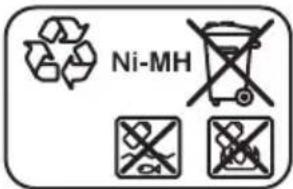
Ni-MH: Nickel metal hydride
Do not dispose of battery packs/batteries into household waste, fire or water. Battery packs/batteries should, if possible, be discharged, collected, recycled or disposed of in an environmental-friendly manner.
Only for EC countries:
Defective or dead out battery packs/batteries must be recycled according the guideline 2006/66/EC.
Batteries no longer suitable for use can be directly returned at:
Great Britain
Robert Bosch Ltd. (B.S.C.)
P.O. Box 98
Broadwater Park
North Orbital Road
Denham
Uxbridge
UB 9 5HJ
Tel. Service: +44 (0844) 736 0109
Fax: +44 (0844) 736 0146
E-Mail: boschservicecentre@bosch.com
Subject to change without notice.
Dr. Egbert Schneider Senior Vice President Engineering
Dr. Eckerhard Strötgen Head of Product Certification
ppa. Amina i.v. Nuoyen
Robert Bosch GmbH, Power Tools Division D-70745 Leinfelden-Echterdingen Leinfelden, 04.03.2010
Montage
natural_image
Technical line drawing of a mechanical device with no visible text or symbolsnatural_image
Technical line drawing of a portable gas stove with fan and vent (no text or symbols)Mode rotation
natural_image
Technical line drawing of a mechanical device with no visible text or symbolsnatural_image
Technical line drawing of a mechanical device with no visible text or symbolsRobert Bosch (France) S.A.S.
Dr. Egbert Schneider Senior Vice President Engineering
Dr. Eckerhard Strötgen Head of Product Certification
ppa. Deuwa
i.v. Puoyen
Robert Bosch GmbH, Power Tools Division D-70745 Leinfelden-Echterdingen Leinfelden, 04.03.2010
Montaje
natural_image
Technical line drawing of a mechanical device with no visible text or symbolsnatural_image
Technical line drawing of a mechanical device with no visible text or symbolsnatural_image
Technical line drawing of a mechanical device with no visible text or symbolsOperación lineal
natural_image
Technical line drawing of a mechanical device with no visible text or symbolsDr. Egbert Schneider Senior Vice President Engineering
Dr. Eckerhard Strötgen Head of Product Certification
ppa. A##u i.v. NuOyen
Robert Bosch GmbH, Power Tools Division D-70745 Leinfelden-Echterdingen Leinfelden, 04.03.2010
Montagem
natural_image
Technical line drawing of a mechanical device with no visible text or symbolsnatural_image
Technical line drawing of a portable electrical device with fan and control panel (no text or symbols)natural_image
Technical line drawing of a mechanical device with no visible text or symbolsnatural_image
Technical line drawing of a mechanical device with no visible text or symbolsDr. Egbert Schneider Senior Vice President Engineering
Dr. Eckerhard Strötgen Head of Product Certification
ppa. Mauwa i.v. Nuoyen
Robert Bosch GmbH, Power Tools Division D-70745 Leinfelden-Echterdingen Leinfelden, 04.03.2010
Montaggio
natural_image
Technical line drawing of a mechanical device with no visible text or symbolsnatural_image
Technical line drawing of a mechanical device with no visible text or symbolsnatural_image
Technical line drawing of a mechanical device with no visible text or symbolsnatural_image
Technical line drawing of a mechanical device with no visible text or symbolsDr. Egbert Schneider Senior Vice President Engineering
Dr. Eckerhard Strötgen Head of Product Certification
ppa. A##u i.v. NuOyen
Robert Bosch GmbH, Power Tools Division D-70745 Leinfelden-Echterdingen Leinfelden, 04.03.2010
Montage
natural_image
Technical line drawing of a mechanical device with no visible text or symbolsnatural_image
Technical line drawing of a mechanical device with no visible text or symbolsRotatiefunctie
natural_image
Technical line drawing of a mechanical device with no visible text or symbolsLijnfunctie
natural_image
Technical line drawing of a mechanical device with no visible text or symbolsPuntfunctie
Dr. Egbert Schneider Senior Vice President Engineering
Dr. Eckerhard Strötgen Head of Product Certification
ppa. A##u i.v. P#o#en
Robert Bosch GmbH, Power Tools Division D-70745 Leinfelden-Echterdingen Leinfelden, 04.03.2010
Montering
Energiforsyning rotationslaser Drift med batterier/akkuer
natural_image
Technical line drawing of a mechanical device with no visible text or symbolsLodret
natural_image
Technical line drawing of a portable electrical device with fan and control panel (no text or symbols)Rotationsdrift
natural_image
Technical line drawing of a mechanical device with no visible text or symbolsLinjefunktion
natural_image
Technical line drawing of a mechanical device with no visible text or symbolsPunktdrift
Bosch Service Center
Telegrafvej 3
2750 Ballerup
Tel. Service Center: +45 (4489) 8855
Fax: +45 (4489) 87 55
E-Mail: vaerktoej@dk.bosch.com
Bortskaffelse
Dr. Egbert Schneider Senior Vice President Engineering
Dr. Eckerhard Strötgen Head of Product Certification
ppa. A##u i.v. NuOyen
Robert Bosch GmbH, Power Tools Division D-70745 Leinfelden-Echterdingen Leinfelden, 04.03.2010
Montage
natural_image
Line drawing of a mechanical device with no visible text or symbolsnatural_image
Technical line drawing of a mechanical device with no visible text or symbolsRotationsfunktion
natural_image
Technical line drawing of a mechanical device with no visible text or symbolsLinjefunktion
natural_image
Technical line drawing of a mechanical device with no visible text or symbolsPunktfunktion
Bosch Service Center
Telegrafvej 3
2750 Ballerup
Danmark
Tel.: +46 (020) 41 44 55
Fax: +46 (011) 18 76 91
Avfallshantering
Dr. Egbert Schneider Senior Vice President Engineering
Dr. Eckerhard Strötgen Head of Product Certification
ppa. A##u i.v. NuOyen
Robert Bosch GmbH, Power Tools Division D-70745 Leinfelden-Echterdingen Leinfelden, 04.03.2010
Montering
natural_image
Technical line drawing of a mechanical device with no visible text or symbolsnatural_image
Technical line drawing of a portable electrical device with no visible text or symbolsRotasjonsdrift
natural_image
Technical line drawing of a mechanical device with no visible text or symbolsLinjedrift
Dr. Egbert Schneider Senior Vice President Engineering
Dr. Eckerhard Strötgen Head of Product Certification
ppa. Mauwa i.v. Nuoyen
Robert Bosch GmbH, Power Tools Division D-70745 Leinfelden-Echterdingen Leinfelden, 04.03.2010
Asennus
natural_image
Line drawing of a mechanical device with no visible text or symbolsnatural_image
Line drawing of a portable kitchen appliance with a side-mounted fan and control panel (no text or symbols)Linjakäyttö
natural_image
Technical line drawing of a mechanical device with no visible text or symbolsPistekäyttö
Dr. Egbert Schneider Senior Vice President Engineering
Dr. Eckerhard Strötgen Head of Product Certification
ppa. Amina i.v. Nuoyen
Robert Bosch GmbH, Power Tools Division D-70745 Leinfelden-Echterdingen Leinfelden, 04.03.2010
Συναρμολόγηση
natural_image
Technical line drawing of a mechanical device with no visible text or symbolsΚάθετη θέση
natural_image
Line drawing of a portable gas stove with fan and vent, no text or symbols presentnatural_image
Technical line drawing of a mechanical device with no visible text or symbolsΓραμμική λειτουργία
Σημειακή λειτουργία
Dr. Egbert Schneider Senior Vice President Engineering
Dr. Eckerhard Strötgen Head of Product Certification
ppa. A##u i.v. P#o#en
Robert Bosch GmbH, Power Tools Division D-70745 Leinfelden-Echterdingen Leinfelden, 04.03.2010
Montaj
natural_image
Line drawing of a mechanical device with no visible text or symbolsnatural_image
Technical line drawing of a portable electrical device with fan and vent, no visible text or symbolsRotasyonlu işletim
natural_image
Technical line drawing of a mechanical device with no visible text or symbolsÇizgisel işletim
natural_image
Technical line drawing of a mechanical device with no visible text or symbolsNoktasal işletim
Bosch San. ve Tic. A.S.
Ahi Evran Cad. No:1 Kat:22
Polaris Plaza
80670 Maslak/Istanbul
Dr. Egbert Schneider Senior Vice President Engineering
Dr. Eckerhard Strötgen Head of Product Certification
ppa. Amina i.v. Nuoyen
Robert Bosch GmbH, Power Tools Division D-70745 Leinfelden-Echterdingen Leinfelden, 04.03.2010
Montaż
natural_image
Technical line drawing of a mechanical device with no visible text or symbolsPozycja pionowa
natural_image
Technical line drawing of a mechanical device with no visible text or symbolsTryb rotacyjny
natural_image
Technical line drawing of a mechanical device with no visible text or symbolsTryb liniowy
natural_image
Technical line drawing of a mechanical device with no visible text or symbolsTryb punktowy
Robert Bosch Sp. z o.o.
Dr. Egbert Schneider Senior Vice President Engineering
Dr. Eckerhard Strötgen Head of Product Certification
ppa. A##u i.v. Nu#gen
Robert Bosch GmbH, Power Tools Division D-70745 Leinfelden-Echterdingen Leinfelden, 04.03.2010
Montáž
natural_image
Technical line drawing of a mechanical device with no visible text or symbolsnatural_image
Technical line drawing of a portable gas stove with fan and vent (no text or symbols)Rotační provoz
natural_image
Technical line drawing of a mechanical device with no visible text or symbolsPřímkový provoz
natural_image
Technical line drawing of a mechanical device with no visible text or symbolsBodový provoz
Bosch Service Center PT
K Vápence 1621/16
692 01 Mikulov
Tel.: +420 (519) 305 700
Fax: +420 (519) 305 705
E-Mail: servis.naradi@cz.bosch.com
www.bosch.cz
Zpracování odpadů
Dr. Egbert Schneider Senior Vice President Engineering
Dr. Eckerhard Strötgen Head of Product Certification
ppa. A##u i.v. P#o#en
Robert Bosch GmbH, Power Tools Division D-70745 Leinfelden-Echterdingen Leinfelden, 04.03.2010
Montáž
natural_image
Technical line drawing of a mechanical device with no visible text or symbolsnatural_image
Line drawing of a portable electric stove with fan and vent, no text or symbols presentRotačná prevádzka
natural_image
Technical line drawing of a mechanical device with no visible text or symbolsČiarová prevádzka
natural_image
Technical line drawing of a mechanical device with no visible text or symbolsBodová prevádzka
Dr. Egbert Schneider Senior Vice President Engineering
Dr. Eckerhard Strötgen Head of Product Certification
ppa. A##u i.v. P#o#en
Robert Bosch GmbH, Power Tools Division D-70745 Leinfelden-Echterdingen Leinfelden, 04.03.2010
Összeszerelés
natural_image
Technical line drawing of a mechanical device with no visible text or symbolsnatural_image
Technical line drawing of a portable gas stove with cooling fan and fan (no text or symbols)A forgó üzem
natural_image
Technical line drawing of a mechanical device with no visible text or symbolsVonal-üzemmód
natural_image
Technical line drawing of a mechanical device with no visible text or symbolsPont-üzemmód
Dr. Egbert Schneider Senior Vice President Engineering
Dr. Eckerhard Strötgen Head of Product Certification

i.v. Nuoyen
Robert Bosch GmbH, Power Tools Division D-70745 Leinfelden-Echterdingen Leinfelden, 04.03.2010
Сборка
natural_image
Technical line drawing of a mechanical device with no visible text or symbolsnatural_image
Technical line drawing of a mechanical device with no visible text or symbolsРотационный режим
natural_image
Technical line drawing of a mechanical device with no visible text or symbolsЛинейный режим
natural_image
Technical line drawing of a mechanical device with no visible text or symbolsТочечный режим
Dr. Egbert Schneider Senior Vice President Engineering
Dr. Eckerhard Strötgen Head of Product Certification
ppa. A##u i.v. NuOyen
Robert Bosch GmbH, Power Tools Division D-70745 Leinfelden-Echterdingen Leinfelden, 04.03.2010
Монтаж
natural_image
Technical line drawing of a mechanical device with no visible text or symbolsnatural_image
Technical line drawing of a portable electrical device with fan and control panel (no text or symbols)Ротаційний режим
natural_image
Technical line drawing of a mechanical device with no visible text or symbolsЛінійний режим
natural_image
Technical line drawing of a mechanical device with no visible text or symbolsТочковий режим
Dr. Egbert Schneider Senior Vice President Engineering
Dr. Eckerhard Strötgen Head of Product Certification
ppa. A##ta i.v. NuOyen
Robert Bosch GmbH, Power Tools Division D-70745 Leinfelden-Echterdingen Leinfelden, 04.03.2010
Montare
Alimentarea cu energie a nivelei cu laser Functionare cu baterii/acumulatori
natural_image
Technical line drawing of a mechanical component with no visible text or symbolsnatural_image
Technical line drawing of a mechanical device with no visible text or symbolsModul rotativ
natural_image
Technical line drawing of a mechanical device with no visible text or symbolsModul liniar
natural_image
Technical line drawing of a mechanical device with no visible text or symbolsModul punctiform
Bosch Service Center
Str. Horia Măcelariu Nr. 30–34,
013937 Bucureşti
Tel. Service scule electrice: +40 (021) 4 05 75 40
Fax: +40 (021) 4 05 75 66
E-Mail: infoBSC@ro.bosch.com
Dr. Egbert Schneider Senior Vice President Engineering
Dr. Eckerhard Strötgen Head of Product Certification

i.v. MacKen
Robert Bosch GmbH, Power Tools Division D-70745 Leinfelden-Echterdingen Leinfelden, 04.03.2010
Монтиране
Захранване на ротационния лазер
natural_image
Technical line drawing of a mechanical device with no visible text or symbolsnatural_image
Line drawing of a portable gas stove with cooling fan and side-mounted unit (no text or symbols)Ротационен режим
natural_image
Technical line drawing of a mechanical device with no visible text or symbolsЛинеен режим
natural_image
Technical line drawing of a mechanical device with no visible text or symbolsТочков режим
Dr. Egbert Schneider Senior Vice President Engineering
Dr. Eckerhard Strötgen Head of Product Certification
ppa. Mauwa i.v. Nuoyen
Robert Bosch GmbH, Power Tools Division D-70745 Leinfelden-Echterdingen Leinfelden, 04.03.2010
Montaža
natural_image
Line drawing of a mechanical device with no visible text or symbolsPostavljajte merni alat na stabilnu podlogu u horizontalnom ili vertikalnom položaju, montirajte ga na stativ 26 ili na zidni držač 30 sa jedinicom za centriranje.
natural_image
Line drawing of a portable gas stove with fan and vent, no text or symbols presentRotacioni rad
Rotacioni rad je posebno preporučljiv pri upotrebi laserskog prijemnika. Možete birati izmedju raznih rotacionih brzina.

natural_image
Technical line drawing of a mechanical device with no visible text or symbolsLinijski rad
natural_image
Technical line drawing of a mechanical device with no visible text or symbolsTačkasti rad
U ovoj vrsti rada se postiže najbolja vidljivost variabilnog laserskog zraka. Ona služi na primer za jednostavno prenošenje visina ili kontrolu pravih linija.

Rotacioni rad (150/300/600 min -1 )
Posle svakog uključivanja nalazi se merni alat u rotacionom radu sa srednjom rotacionom brzinom.
Za promenu linijskog rada u rotacioni pritisnite taster za rotacioni rad 5. Rotacioni rad startuje sa srednjom rotacionom brzinom.
Za promenu rotacione brzine pritiskajte ponovo taster za rotacioni rad 5, sve dok se ne dostigne željena brzina.
Pri radu sa laserskim prijemnikom trebali bi izabrati najveću rotacionu brzinu. Pri radu bez laserskog prijemnika smanjite radi bolje vidljivosti laserskog zraka rotacionu brzinu i upotrebite laserske naočare 29.

Linijski rad, tačkasti rad (10°/25°/50°, 0°)
Dr. Egbert Schneider Senior Vice President Engineering
Dr. Eckerhard Strötgen Head of Product Certification
ppa. A##u i.v. Nu#gen
Robert Bosch GmbH, Power Tools Division D-70745 Leinfelden-Echterdingen Leinfelden, 04.03.2010
Montaža
natural_image
Technical line drawing of a mechanical device with no visible text or symbolsMerilno orodje postavite na stabilno podlago v vodoravni ali navpični položaj in ga montirajte na stativ 26 ali na stensko držalo 30 z izravnalno enoto.
natural_image
Technical line drawing of a portable electrical device with fan and control panel (no text or symbols)natural_image
Technical line drawing of a mechanical device with no visible text or symbolsČrtno obratovanje
natural_image
Technical line drawing of a mechanical device with no visible text or symbolsDr. Egbert Schneider Senior Vice President Engineering
Dr. Eckerhard Strötgen Head of Product Certification

i.v. Nuoyen
Robert Bosch GmbH, Power Tools Division D-70745 Leinfelden-Echterdingen Leinfelden, 04.03.2010
Montaža
Električno napajanje rotacionog lasera
Rad sa baterijama/aku-baterijom
natural_image
Technical line drawing of a mechanical device with no visible text or symbolsStavite mjerni alat na stabilnu podlogu, u horizontalni ili vertikalni položaj, montirajte ga na stativ 26 ili na zidni držač 30 sa jedinicom za izravnavanje.
natural_image
Technical line drawing of a portable electrical device with fan and vent (no text or symbols)Rotacioni rad
natural_image
Technical line drawing of a mechanical device with no visible text or symbolsLinijski rad
Kod ovog načina rada varijabilna laserska zraka se poniče u ograničenom kutu otvora. Time se povećava vidljivost laserske zrake u odnosu na rad sa rotacijom. Možete birati među različitim kutovima otvora.

natural_image
Technical line drawing of a mechanical device with no visible text or symbolsTočkasti rad
Dr. Egbert Schneider Senior Vice President Engineering
Dr. Eckerhard Strötgen Head of Product Certification
ppa. A##u i.v. NuOyen
Robert Bosch GmbH, Power Tools Division D-70745 Leinfelden-Echterdingen Leinfelden, 04.03.2010
Montaaž
Pöördlaseri toide
Patareide/akude kasutamine
natural_image
Technical line drawing of a mechanical device with no visible text or symbolsnatural_image
Technical line drawing of a mechanical device with no visible text or symbolsPöördliikumisrežiim
natural_image
Technical line drawing of a mechanical device with no visible text or symbolsJoonliikumisrežiim
natural_image
Technical line drawing of a mechanical device with no visible text or symbolsPunktrežiim
Dr. Egbert Schneider Senior Vice President Engineering
Dr. Eckerhard Strötgen Head of Product Certification
ppa. A##u i.v. P#o#en
Robert Bosch GmbH, Power Tools Division D-70745 Leinfelden-Echterdingen Leinfelden, 04.03.2010
Montāža
natural_image
Technical line drawing of a mechanical device with no visible text or symbolsnatural_image
Line drawing of a portable gas stove with fan and vent, no text or symbols presentRotācijas režīms
natural_image
Technical line drawing of a mechanical device with no visible text or symbolsLinijas režims
natural_image
Technical line drawing of a mechanical device with no visible text or symbolsPunkta režims
Dr. Egbert Schneider Senior Vice President Engineering
Dr. Eckerhard Strötgen Head of Product Certification
ppa. A##u i.v. P#o#en
Robert Bosch GmbH, Power Tools Division D-70745 Leinfelden-Echterdingen Leinfelden, 04.03.2010
Montavimas
natural_image
Line drawing of a mechanical device with no visible text or symbolsnatural_image
Technical line drawing of a mechanical device with no visible text or symbolsRotacinis režimas
natural_image
Technical line drawing of a mechanical device with no visible text or symbolsLinijinis režimas
natural_image
Technical line drawing of a mechanical device with no visible text or symbolsTaškinis režimas
natural_image
Technical line drawing of a mechanical device with no visible text or symbols垂直設置
natural_image
Technical line drawing of a mechanical device with no visible text or symbolsローテーションモード
natural_image
Technical line drawing of a mechanical device with no visible text or symbolsラインモード
natural_image
Technical line drawing of a mechanical device with no visible text or symbolsポイントモード
natural_image
Technical line drawing of a mechanical component with no visible text or symbols垂直位置
natural_image
Technical line drawing of a mechanical device with no visible text or symbols旋转测量
natural_image
Technical line drawing of a mechanical device with no visible text or symbols线段测量
natural_image
Technical line drawing of a mechanical device with no visible text or symbols点状测量
natural_image
Technical line drawing of a mechanical component with no visible text or symbols수직 위치
natural_image
Technical line drawing of a portable gas stove with fan and vent (no text or symbols)회전 작동
natural_image
Line drawing of a portable radio device with no visible text or symbols선작동
natural_image
Technical line drawing of a mechanical device with no visible text or symbols점 작동
Robert Bosch Korea Mechanics and Electronics Ltd.
전동공구 사업부

natural_image
Illustration of a person using surveying equipment to measure height measurement (no text or symbols present)natural_image
Line drawing of a portable kitchen appliance with a rotary knob and control panel (no text or symbols)الإنتشغير الحطي
natural_image
Line drawing of a kitchen appliance with a rotary knob and handle (no text or symbols)لإتشغير الإنيقطي
natural_image
Line drawing of a portable electronic device with a central fan and control panel (no text or symbols)للاتشغير الإداراني
(⁻¹ د crimesة 150/300/600)
1
natural_image
Line drawing of a mechanical device with no visible text or symbolsالROUGH الأفقي
الوضع العامودي

• اح Subject على NCAA Agricultural and Economic Affairs Agricultural and Agricultural and Agricultural and Agricultural and Agricultural and Agricultural and Agricultural and Agricultural and Agricultural and Agricultural and Agricultural and Agricultural and Agricultural and Agricultural and Agricultural and Agricultural and Agricultural and Agricultural and Agricultural and Agricultural and Agricultural and Agricultural and Agricultural and Agricultural and Agricultural and Agricultural and Agricultural and Agricultural and Agricultural and Agricultural and Agricultural and Agricultural and Agricultural and Agricultural and Agricultural and Agricultural and Agricultural and Agricultural and Agricultural and Agricultural and Agricultural and Agricultural and Agricultural and Agricultural and Agricultural and Agricultural and Agricultural and Agricultural and Agricultural and Agricultural and Agricultural,
وصف العمل
natural_image
Illustration of a person standing near surveying equipment with motion indicators (no text or symbols)natural_image
Line drawing of a portable gas stove with cooling fan and fan base (no text or symbols)عملکرد خطی
natural_image
Technical line drawing of a mechanical device with no visible text or symbols
natural_image
Technical line drawing of a mechanical device with no visible text or symbolsنحوه عملکرد چرخشى
(150/300/600 min -1 )

natural_image
Line drawing of a mechanical device with no visible text or symbols
وضعیت عمودی


- GRL Professional
- BOSCH
- Sicherheitshinweise
- Rotationslaser
- Montage
- Rotationsbetrieb
- Linienbetrieb
- Punktbetrieb
- Rotational Laser Level
- GRL 250 HV/GRL 300 HV
- GRL 300 HVG
- Battery Charger
- Functional Description
- Intended Use
- Product Features
- Noise Information
- Declaration of Conformity CE
- Assembly
- Power Supply of the Rotational Laser Level
- Operation with Batteries/Rechargeable Batteries
- Operation with Battery Pack
- Charge-control Indicator
- Operation
- Starting Operation of the Rotational Laser Level
- Setting Up the Measuring Tool
- Switching On and Off
- Operating Modes of the Rotational Laser Level
- Overview
- Rotational Operation
- Line Operation
- Point Operation
- Rotational Operation (150/300/600 min -1 )
- Line Operation, Point Operation (10°/25°/50°, 0°)
- Turning the Rotational Plane when in the Vertical Position
- Automatic Levelling of the Rotational Laser Level
- Shock-warning Function
- Levelling Accuracy of the Rotational Laser Level
- Influences on Accuracy
- Accuracy Check of the Measuring Tool
- Working Advice
- Laser Viewing Glasses (Accessory)
- Working with the Laser Receiver (Accessory)
- Working with the Remote Control (Accessory)
- Working with the Tripod (Accessory)
- Working with Wall Mount/Alignment Unit (Accessory) (see figure A)
- Working with the Ceiling Measurement Plate (see figure A)
- Working with the Measuring Plate (Accessory)
- Working with the Measuring Rod (Accessory) (see figure H)
- Work Examples
- Projecting/Checking Heights (see figure B)
- Parallel Alignment of a Plumb Beam/Projecting Right Angles (see figure C)
- Indicating a Plumb Line/Vertical Plane (see figure D)
- Working without Laser Receiver (see figure E)
- Working with the Laser Receiver (see figure F)
- Measuring Over Long Distances (see figure G)
- Working Outdoors (see figure H)
- Maintenance and Service
- Maintenance and Cleaning
- After-sales Service and Customer Assistance
- www.bosch-pt.com
- Great Britain
- Ireland
- Australia, New Zealand and Pacific Islands
- Republic of South Africa
- Customer service
- Gauteng - BSC Service Centre
- KZN - BSC Service Centre
- Western Cape - BSC Service Centre
- Bosch Headquarters
- People's Republic of China
- China Mainland
- HK and Macau Special Administrative Regions
- Indonesia
- Philippines
- Malaysia
- Thailand
- Singapore
- Vietnam
- Disposal
- Only for EC countries:
- Battery packs/batteries:
- Mode rotation
- Montaje
- Operación lineal
- Montagem
- Montaggio
- Rotatiefunctie
- Lijnfunctie
- Puntfunctie
- Montering
- Energiforsyning rotationslaser Drift med batterier/akkuer
- Rotationsdrift
- Linjefunktion
- Punktdrift
- Bortskaffelse
- Rotationsfunktion
- Punktfunktion
- Avfallshantering
- Rotasjonsdrift
- Linjedrift
- Asennus
- Linjakäyttö
- Pistekäyttö
- Συναρμολόγηση
- Γραμμική λειτουργία
- Σημειακή λειτουργία
- Montaj
- Rotasyonlu işletim
- Çizgisel işletim
- Noktasal işletim
- Montaż
- Tryb rotacyjny
- Tryb liniowy
- Tryb punktowy
- Montáž
- Rotační provoz
- Přímkový provoz
- Bodový provoz
- Zpracování odpadů
- Rotačná prevádzka
- Čiarová prevádzka
- Bodová prevádzka
- Összeszerelés
- A forgó üzem
- Vonal-üzemmód
- Pont-üzemmód
- Сборка
- Ротационный режим
- Линейный режим
- Точечный режим
- Монтаж
- Ротаційний режим
- Лінійний режим
- Точковий режим
- Montare
- Alimentarea cu energie a nivelei cu laser Functionare cu baterii/acumulatori
- Modul rotativ
- Modul liniar
- Modul punctiform
- Монтиране
- Захранване на ротационния лазер
- Ротационен режим
- Линеен режим
- Точков режим
- Montaža
- Rotacioni rad
- Linijski rad
- Tačkasti rad
- Rotacioni rad (150/300/600 min -1 )
- Linijski rad, tačkasti rad (10°/25°/50°, 0°)
- Črtno obratovanje
- Električno napajanje rotacionog lasera
- Rad sa baterijama/aku-baterijom
- Točkasti rad
- Montaaž
- Pöördlaseri toide
- Patareide/akude kasutamine
- Pöördliikumisrežiim
- Joonliikumisrežiim
- Punktrežiim
- Montāža
- Rotācijas režīms
- Linijas režims
- Punkta režims
- Montavimas
- Rotacinis režimas
- Linijinis režimas
- Taškinis režimas
- 회전 작동
- 선작동
- 점 작동
- 전동공구 사업부
- وصف العمل
- عملکرد خطی
- نحوه عملکرد چرخشى
- (150/300/600 min -1 )
Brand : BOSCH
Model : GRL 300 HVG Professional
Category : Rangefinder