 — Electronic device stand — Mode d'emploi PDF")
PDK-TS01(-L) - Electronic device stand PIONEER - Free user manual and instructions
Find the device manual for free PDK-TS01(-L) PIONEER in PDF.
| Product Type | Table top stand for plasma screen |
| Brand | Pioneer |
| Model | PDK-TS01(-L) |
| Dimensions (L x H x D) | 566 x 508 x 339 mm |
| Weight (stand only) | 4.0 kg |
| Total weight with 50" screen | 42.9 kg |
| Total weight with 43" screen | 35.5 kg |
| Material | Metal |
| Power supply | Not applicable (mechanical stand) |
| Use | Indoor only, on a flat and stable surface |
| Compatibility | Pioneer 43" and 50" plasma screens |
| Installation | Requires at least two people; floor fixing recommended |
| Maintenance | Clean with a soft, dry cloth; avoid solvents |
| Package contents | 2 support pillars, 2 M8x20 bolts, 2 M8x40 bolts, 2 stabilizing bolts, hex key |
| Spare parts | Available from Pioneer distributor |
| Safety | Fix to wall or floor with rope and hooks (not supplied) to prevent tipping |
Frequently Asked Questions - PDK-TS01(-L) PIONEER
User questions about PDK-TS01(-L) PIONEER
0 question about this device. Answer the ones you know or ask your own.
Ask a new question about this device
Download the instructions for your Electronic device stand in PDF format for free! Find your manual PDK-TS01(-L) - PIONEER and take your electronic device back in hand. On this page are published all the documents necessary for the use of your device. PDK-TS01(-L) by PIONEER.
USER MANUAL PDK-TS01(-L) PIONEER
Operating instructions
Mode d'emploi
Bedienungsanleitung
natural_image
Isometric line drawing of a rectangular electronic component with a recessed top and side slot (no text or symbols)- ベースカバー ...... 1
natural_image
Technical line drawing of two vertical metal supports with mounting holes (no text or symbols)natural_image
Isometric line drawing of a metal frame structure with two vertical posts and mounting base (no text or symbols)natural_image
Technical line drawing of a computer monitor rear panel with mounting brackets and ventilation slots (no text or symbols)Thank you for buying this Pioneer product.
Please read through these operating instructions so you will know how to operate your model properly. After you have finished reading the instructions, put them away in a safe place for future reference.

CAUTION
This symbol refers to a hazard or unsafe practice which can result in personal injury or property damage.
Installation
- Consult your dealer if you encounter any difficulties with this installation.
- Pioneer is not liable for any damage resulting from improper installation, improper use, modification, or natural disasters.
Cautions
- This table top stand was exclusively designed for plasma displays produced by PIONEER.
- Do not use this stand for a plasma display or any other purpose that is not specified. The stand should not be modified and should only be used for plasma displays.
- Improper installation may result in the stand falling over and cause serious injury. Be sure to have the plasma display lying flat when attaching the stand to the main display.
- Installation Location
(a) Make sure to install the stand in a location that can sufficiently support the combined weight of the stand and the display.
(b) The installation location should be a completely flat and stable surface. Take proper precautions when installing the stand to make sure that the weight of the display is equally distributed throughout the stand.
(c) Do not install this stand outdoors, at a hot spring, or near a beach.
(d) Do not install this stand where it may be subjected to vibration or shock.
- (a) Assemble the stand in accordance with all of the instructions and securely stabilize the stand with screws at all locations that are indicated.
There have been cases where after installing the display, damage has occurred from the stand falling over or similar situations.
(b) To assure that the display is installed safely, installation should be performed with more than two people.
(c) Before installation, turn off the power for the display and peripheral devices, then remove the power cord plug from the power outlet.
Check That You Have All the Parts
natural_image
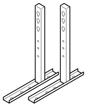
Isometric line drawing of a rectangular tray with a side tab (no text or symbols)- Base cover .... 1

natural_image
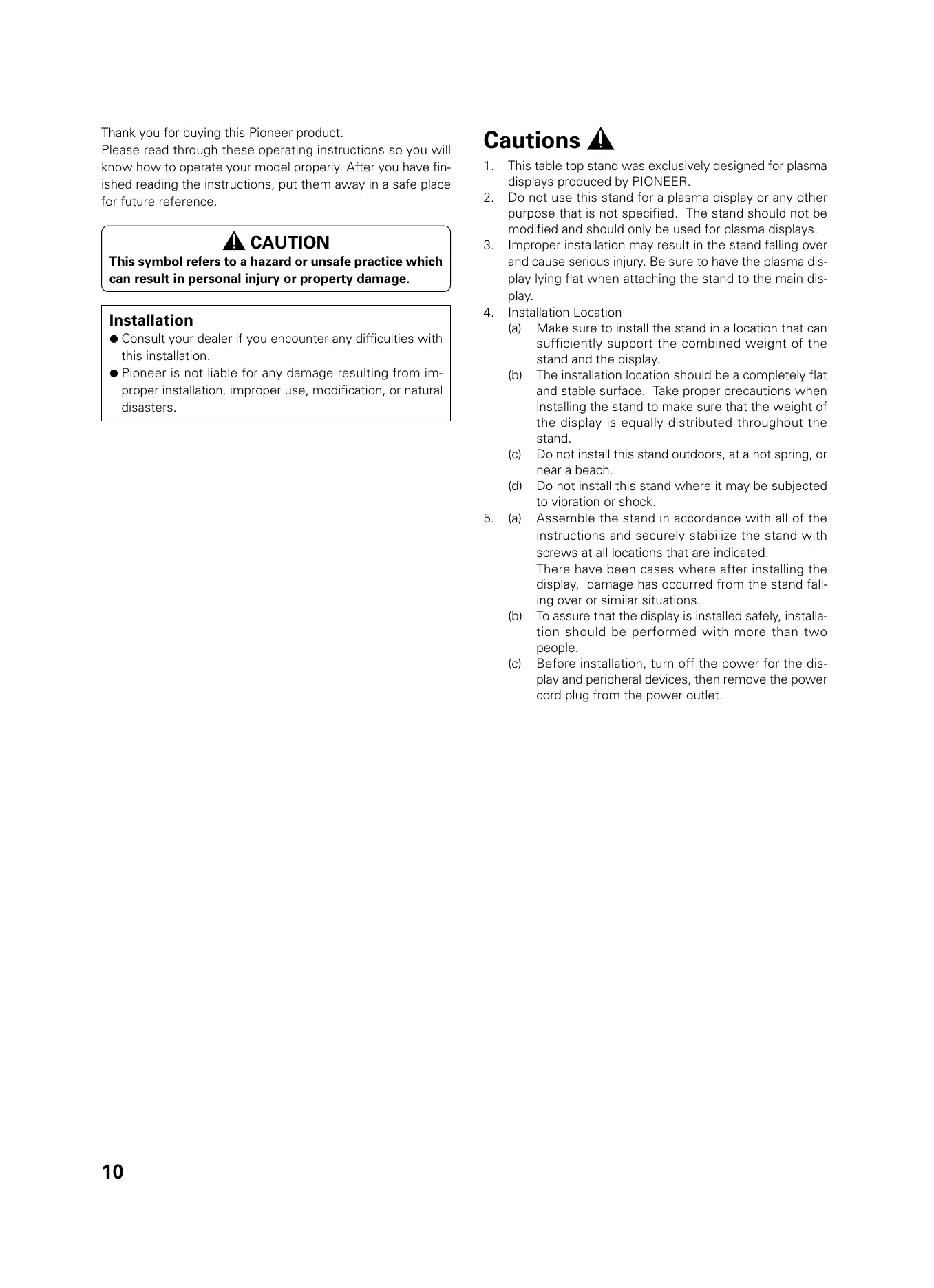
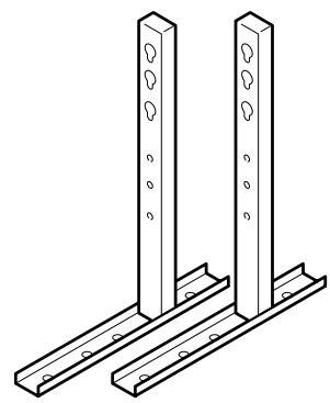
Technical line drawing of two vertical metal supports with mounting holes (no text or symbols)- Stand pipes (left and right, interchangable) .... 2
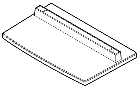
- Hexagonal wrench
.... 1

- Screws (4 x 8) ...... 4

- Installation bolts ①
(M8 x 20).... 2
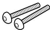
- Installation bolts ②
(M8 x 40) ...... 2

- Stabilization bolts 2
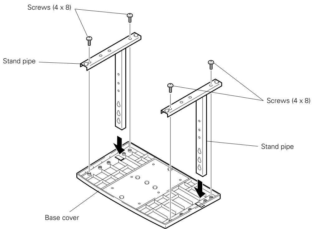
1. Stand assembling
■ Assembling Steps
- Turn the base cover over so the underside is facing up.
- Insert the stand pipes into the base cover.
- Use the included screws to stabilize the stand pipes.
2. Stand attaching to the Plasma Display
■ Normal Installation
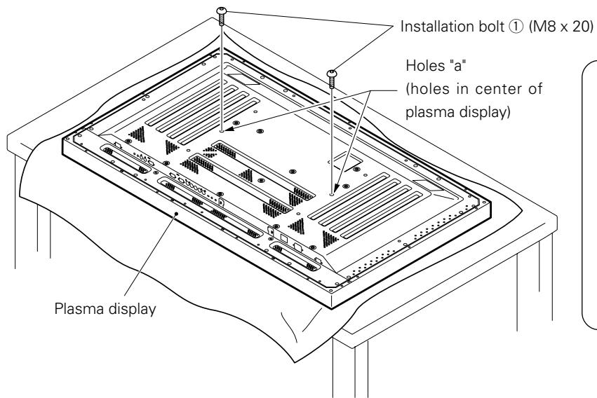
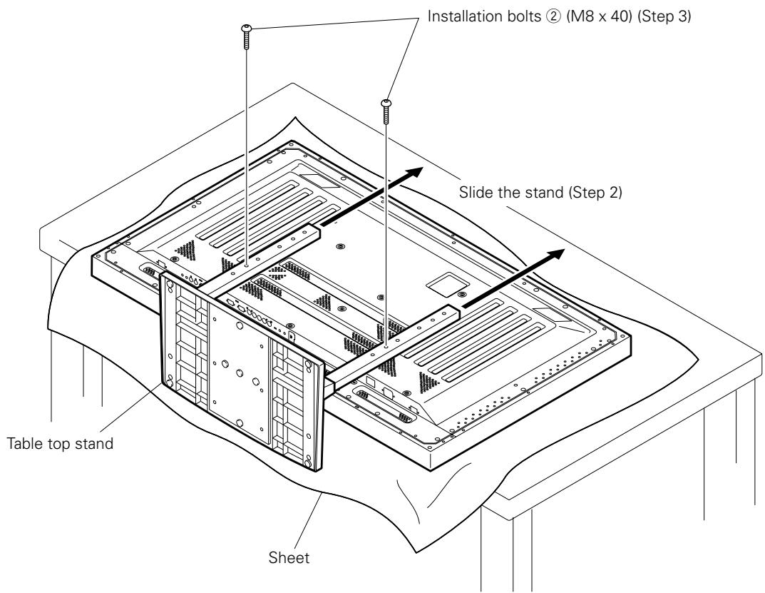
Step 1. With the plasma display lying flat, insert and secure the two Installation bolts ① (M8 x 20) in the holes "a" located in the plasma display housing.
At this point, tighten these bolts ① only until the threads are no longer visible when viewed from t he side (you will be unable to attach the display if the bolts are screwed in completely).
Installation bolt ①
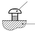
Plasma display housing

Stop screwing down the bolt when the threads are no longer visible.
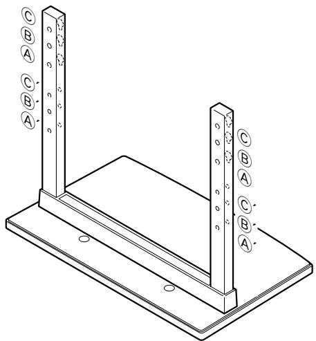
Regarding the stand pipe screw holes when the stand is used as a desktop stand
Table: Stand pipe screw holes when the stand is used as a desktop stand
| Plasma display model | Specifications | Screw holes used with stand orientation |
| 50" | Normal use | B, B' |
| With optional speakers attached to both sides of display | ||
| 43" | Without optional speakers | A, A' |
| With optional speakers attached to both sides of display | ||
| With optional speakers attached at bottom of display | B, B' |
Note: Holes © and ©' are for attaching options available separately, etc.
natural_image
Technical line drawing of a structural support frame with two vertical posts and mounting base (no text or symbols)Step 2. As shown in figure, hook the stand pipe holes (either pipe Ⓐ or Ⓑ) onto the screw heads of the installation bolts ①, then slide the stand upwards to the main plasma display until it engages the installation bolts ① (once put together with the display, the stand will slides no more than 19 mm (3/4 inch)).
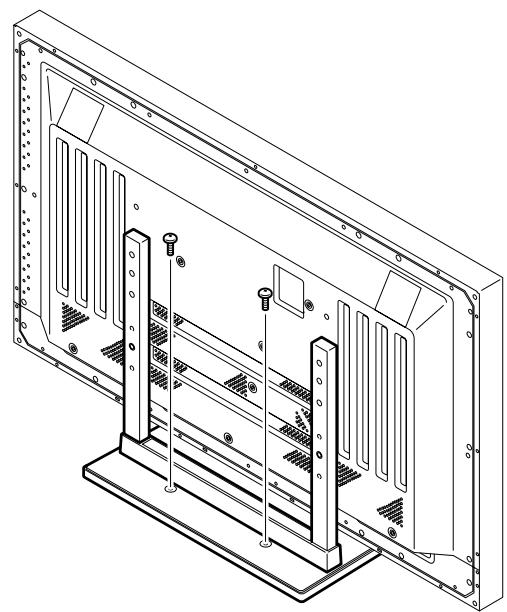
Step 3. Pass the installation bolts ② (M8 x 40) through the stand pipes and tighten the installation bolts securely with the included hexagonal wrench (The holes should be used in the proper combinations, A–A' and B–B').
Step 4. Tighten the installation bolts ① securely with the hexagonal wrench provided.

Notes
- Place a sheet or protective cover to protect the display from scratches or damage.
- Assemble only with the plasma display lying flat on a table or similar surface.
- Insert the bolts vertically in the holes and tighten them, but do not apply excessive pressure that tightens them more than necessary.
- Move the stand so that the stand screw holes and the nuts that connect the main display line up correctly.
- The display is a 50" model that weighs approximately 40 kilograms (88 lb) and has little depth, making the display very unstable. For this reason, at least two people are required for setup and installation.
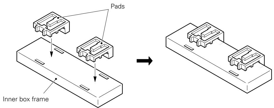
■ Instructions for using the main display packing material as a stand for the working on the display (50" display model is shown in the figure.)
- Main plasma display packaging setup
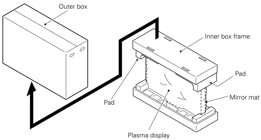
Step 1. Construct the stand for the plasma display using the inner box frame and pads shown in the figure above (all pads are identical).
Step 2. Set the plasma display down on the pads as shown in the figure below.
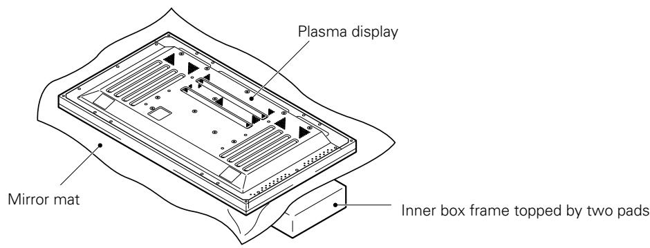
Step 3. Follow the instructions in Steps 1-4 in "Normal Installation" to attach the stand to the plasma display.
3. After assembling, connect the stand to the floor to prevent from falling over.
■ Stabilizing to the floor
- Use screws (sold separately) to attach and stabilize the stand.
natural_image
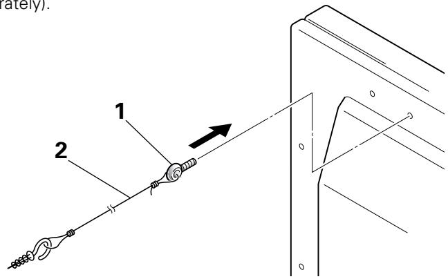
Technical line drawing of a computer monitor rear panel with mounting brackets and screw holes (no text or symbols)■ Sample use of the stabilization bolts (50" display model is shown in the figure.)
- Attach the stabilization bolts that come with the stand to the plasma display.
- Stabilize the display by connecting to a wall or standing beam with a strong cord.
(Repeat the same steps in the laterally direction to stabilize the assembly to the left and right.)
Use cord and hooks that are available on the market (sold separately).
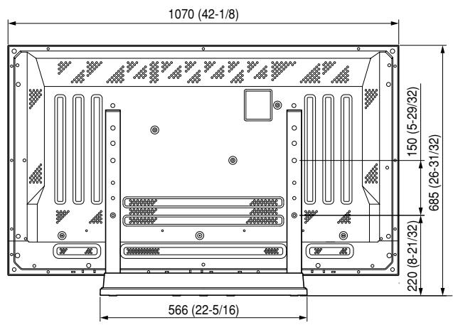
■ Installation coordinates for screws used to stabilize the stand to the floor
* When stabilizing the stand to the floor, use M6 with a length above 20 mm (25/32 inch).
Units: mm (inch)
![248 (9-3/4) 485 (19-3/32) [50" display] 411 (16-3/16) [43" display] 64 (2-17/32) 275 (10-13/16) 11.5 (7/16)](/content/2024/12/118646/images/23495d11aabfddd0ebdba0c203521af1fc9979bb8eb20a507d568d3ea425af87.jpg)
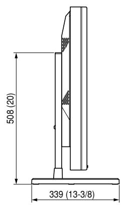
■ Specifications
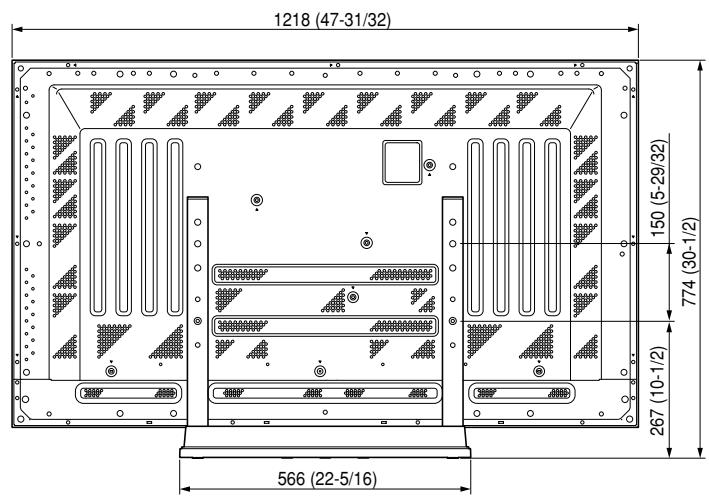
Dimensions 566 (W) x 508 (H) x 339 (D) mm
(22-5/16 (W) × 20 (H) × 13-3/8 (D) in.)
Weight 4.0 kg (8.82 lb)
42.9 kg (94.58 lb) (When the 50" plasma display is attached)
35.5 kg (78.27 lb) (When the 43" plasma display is attached)
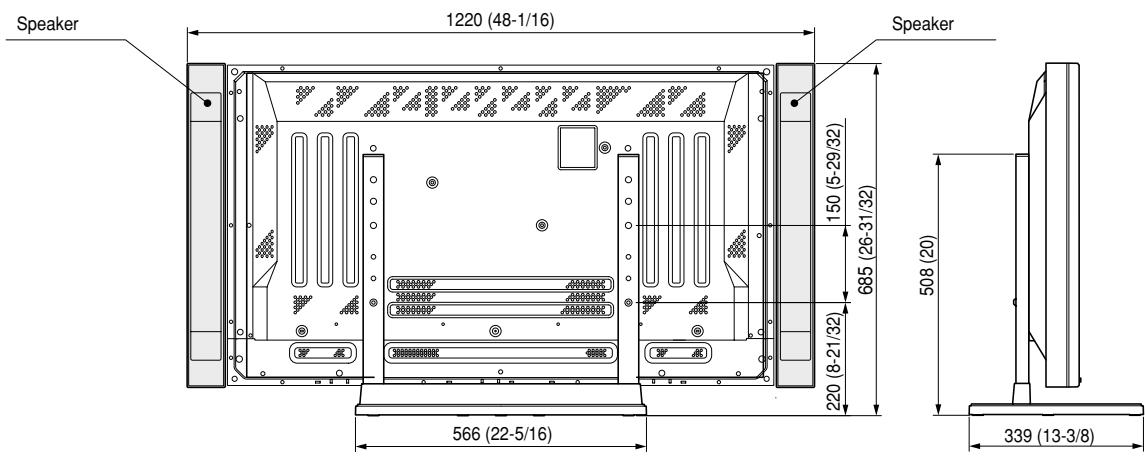
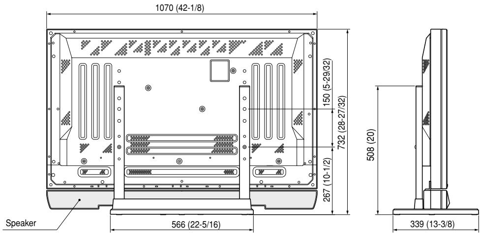
■ Dimensions Diagram
Units: mm (inch)
50" display under normal use (without optional speakers)
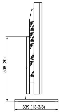
50" display with optional speakers attached to both sides of display
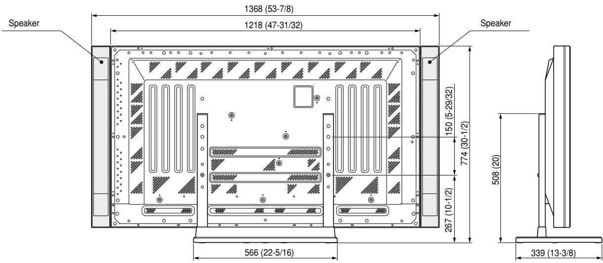
43" display without optional speakers
43" display with optional speakers attached to both sides of display
43" with optional speakers attached at bottom of display
natural_image
Isometric line drawing of a rectangular electronic component with a recessed top and base (no text or symbols)- Couverture de base .... 1

natural_image
Technical line drawing of two vertical metal supports with mounting holes (no text or symbols)natural_image
Technical line drawing of a computer monitor rear panel with mounting brackets and screw holes (no text or symbols)natural_image
Isometric line drawing of a rectangular electronic component with a recessed top and side slots (no text or symbols)- Unterlage .... 1

natural_image
Technical line drawing of two vertical metal supports with mounting holes (no text or symbols)natural_image
Technical line drawing of a metal frame structure with two vertical posts and mounting holes (no text or symbols)natural_image
Technical line drawing of a computer monitor rear panel with mounting brackets and ventilation slots (no text or symbols)natural_image
Isometric line drawing of a rectangular electronic component with a recessed top and base (no text or symbols)natural_image
Technical line drawing of two vertical metal supports with mounting holes (no text or symbols)natural_image
Isometric line drawing of a metal frame structure with two vertical posts and mounting holes (no text or symbols)natural_image
Technical line drawing of a computer monitor rear panel with mounting base and ventilation slots (no text or symbols)natural_image
Isometric line drawing of a rectangular electronic component with a recessed top and side slots (no text or symbols)• Voetstuk .... 1

natural_image
Technical line drawing of two vertical metal supports with mounting holes (no text or symbols)natural_image
Technical line drawing of a metal frame structure with two vertical posts and mounting base (no text or symbols)natural_image
Technical line drawing of a computer monitor rear panel with mounting base and ventilation slots (no text or symbols)natural_image
Isometric line drawing of a rectangular electronic component with a recessed top and side slots (no text or symbols)- Bottenskydd .... 1
natural_image
Technical line drawing of two vertical metal supports with mounting holes (no text or symbols)natural_image
Isometric line drawing of a metal frame structure with two vertical posts and mounting base (no text or symbols)natural_image
Technical line drawing of a computer monitor rear panel with mounting brackets and ventilation slots (no text or symbols)Published by Pioneer Corporation. Copyright © 2001 Pioneer Corporation. All rights reserved.
natural_image
Isometric line drawing of a rectangular electronic component with a recessed top and base (no text or symbols)natural_image
Technical line drawing of two vertical metal supports with mounting holes (no text or symbols)natural_image
Technical line drawing of a metal frame structure with two vertical posts and mounting base (no text or symbols)natural_image
Technical line drawing of a computer monitor rear panel with mounting feet and ventilation grilles (no text or symbols)natural_image
Isometric line drawing of a rectangular electronic component with a recessed top and base (no text or symbols)- 底座 …… 1

natural_image
Technical line drawing of two vertical metal supports with mounting holes (no text or symbols)- 立管(左右通用)…… 2
- 内六角扳手……1

- 螺釘(4×8)… 4

- 固定螺栓①
(M8 × 20)……2
natural_image
Technical line drawing of a metal frame structure with two vertical posts and mounting base (no text or symbols)natural_image
Technical line drawing of a computer monitor rear panel with mounting feet and ventilation slots (no text or symbols)■ 地板固定螺釘的安裝坐標
Published by Pioneer Corporation. Copyright © 2001 Pioneer Corporation. All rights reserved.
パイオニア株式会社
PIONEER ELECTRONICS AUSTRALIA PTY.LTD. 178-184 Boundary Road, Braeside, Victoria 3195, Australia, TEL: 61-39-586-6300
PIONEER ELECTRONICS ASIACENTRE PTE. LTD. 253 Alexandra Road #04-01, Singapore 159936, TEL: 65-472-1111
PIONEER HIGH FIDELITY TAIWAN CO., LTD. 13FL., No44 Chung Shan North Road, Sec.2. Taipei, Taiwan, TEL: 886-2-2521-3588
PIONEER ELECTRONICS (CHINA) LTD. Room 1704-06, 17/F World Trade Centre, 280 Gloucester Rd. Causeway Bay, Hong Kong, TEL: 852-2848-6488
PIONEER GULF FZE Lob 11-017, Jebel Ali Free Zone P.O. BOX 61226, Jebel Ali, Dubai, United Arab Emirates, TEL: 971-4-8815756
PIONEER ELECTRONICS MEXICO S.A. DE C.V. San Lorenzo 1009 3er Piso Desp. 302 Col. Del Valle Mexico D.F. C.P. 03100 TEL: 52-55-6588-5290
- CAUTION
- This symbol refers to a hazard or unsafe practice which can result in personal injury or property damage.
- Installation
- Cautions
- Check That You Have All the Parts
- Stand assembling
- ■ Assembling Steps
- Stand attaching to the Plasma Display
- ■ Normal Installation
- Regarding the stand pipe screw holes when the stand is used as a desktop stand
- Notes
- ■ Instructions for using the main display packing material as a stand for the working on the display (50" display model is shown in the figure.)
- After assembling, connect the stand to the floor to prevent from falling over.
- ■ Stabilizing to the floor
- ■ Sample use of the stabilization bolts (50" display model is shown in the figure.)
- ■ Installation coordinates for screws used to stabilize the stand to the floor
- ■ Specifications
- ■ Dimensions Diagram
- ■ 地板固定螺釘的安裝坐標
- パイオニア株式会社
Brand : PIONEER
Model : PDK-TS01(-L)
Category : Electronic device stand