
PDK-TS30 - Electronic device stand PIONEER - Free user manual and instructions
Find the device manual for free PDK-TS30 PIONEER in PDF.

| Product Type | Tabletop Stand for Plasma TV |
| Brand | PIONEER |
| Model | PDK-TS30 |
| Compatibility | Pioneer PDP-608ZD / PDP-608ZDA Plasma TVs |
| Dimensions (W × H × D) | 920 mm × 222.4 mm × 380 mm |
| Net Weight | 5.7 kg |
| Main Material | Steel and Plastic |
| Color | Black |
| Maximum Load Capacity | Approximately 55.5 kg (weight of compatible TV) |
| Main Functions | Stable stand with anti-tip attachment, floor or shelf installation |
| Package Contents | Table cover, left and right support columns, anti-tip straps (×4), installation screws (M6×20mm ×4, M5×10mm ×6, M4×10mm ×4), instruction manual |
| Safety | Anti-tip device with hooks and straps, wall mounting recommendation |
| Installation | Requires two people, tools: Phillips screwdriver |
| Maintenance and Cleaning | Wipe with a soft, dry cloth. Do not use solvents. |
| Repairability | Spare parts available from Pioneer or authorized dealer |
Frequently Asked Questions - PDK-TS30 PIONEER
User questions about PDK-TS30 PIONEER
0 question about this device. Answer the ones you know or ask your own.
Ask a new question about this device
Download the instructions for your Electronic device stand in PDF format for free! Find your manual PDK-TS30 - PIONEER and take your electronic device back in hand. On this page are published all the documents necessary for the use of your device. PDK-TS30 by PIONEER.
USER MANUAL PDK-TS30 PIONEER
Operating Instructions
Mode d'emploi
Bedienungsanleitung
Thank you for buying Pioneer's product.
Please read through the Operating Instructions to learn how to operate your model safely and properly.
Please be advised to keep the Operating Instructions in your place for future reference.
Installation
- Consult your dealer if you encounter any difficulties with this installation.
- Pioneer is not liable for any damage resulting from improper installation, improper use, modification, or natural disasters.
IMPORTANT NOTICE
Record the model number and serial number of this equipment below.
Model No.
Serial No.
Keep these numbers for future use.
Contents
Cautions 8
Checking the Standard Accessories 9
Assembling the Stand 9
Attaching the Light-blocking Shield
(PDK-TS30A only) 10
Attaching the Plasma Television 11
Installing the Product on a Rack etc. 11
Preventing Equipment from Falling Over 12
Specifications 12
Dimensions Diagram 13

CAUTION
This symbol refers to a hazard or unsafe practice which can result in personal injury or property damage.
Cautions

This product is a table top stand exclusively designed for plasma televisions (PDP-608ZD / PDP-608ZDA) from Pioneer.
Use with other model is capable of resulting in instability causing possible injury. For further information, please contact the store where you purchased your display.
Do not install or modify the product other than specified.
Do not use this stand for a Plasma television other than those designated and do not modify it or use it for other purposes.
Installation Location
- Select a location that is strong enough to support the weight of the stand and the displays.
- Make sure to place it in a level and stable location.
- Do not install it outdoors, at a hot spring, or near a beach.
- Do not install the stand where it may be subjected to vibration or shock.
Assembling and Installation
- Assemble the stand in accordance with the assembly instructions and securely attach all screws at the designated locations.
There have been cases where unforeseen accidents such as the equipment breaking or falling over occurred after the installation of the display because the stand was not installed as instructed. - The display must always be installed by two or more people to assure it is installed safely.
- Before installation, turn off the power for the display and peripheral devices then remove the power cord plug from the power outlet.
Prevent accidents caused by the product falling over by taking reliable measures to prevent it from falling over (see Page 12).
Checking the Standard Accessories
Check to make sure that you have all the standard accessories before assembly and installation.
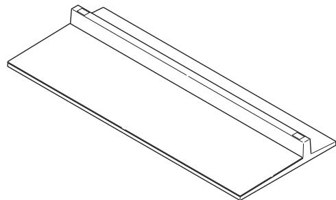
- Base cover × 1
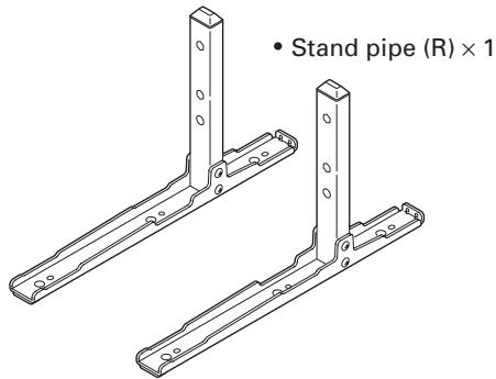
- Stand pipe (L) × 1
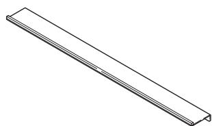
Light-blocking shield × 1 (PDK-TS30A only)
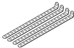
- Fall-prevention strap × 4

- Operating instructions (this document) × 1
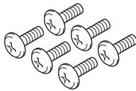
- Screw ① (M5 × 10 mm: black) × 6
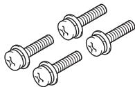
- Installation screw ② (M6 × 20 mm: black) × 4
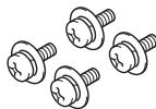
- Screw ③ (M4 × 10 mm: black) × 4
Assembling the Stand
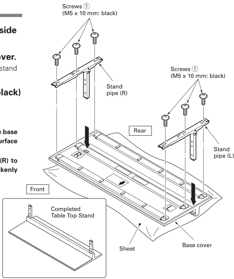
Assembly Procedure
1 Turn the base cover over so the underside is facing up.
2 Insert the stand pipes into the base cover. Insert stand pipe (R) into the side marked "R" and stand pipe (L) into the side marked "L".
3 Tighten the screws ① (M5×10 mm: black) to stabilize the stand pipes.
Note
- Assemble the stand with a soft sheet placed under the base cover. If a sheet is not laid before assembly, the front surface of the base cover may be scratched.
- Please take care when installing stand pipes (L) and (R) to ensure that they are in the correct positions. Mistakenly installing the stand pipes may damage the stand.
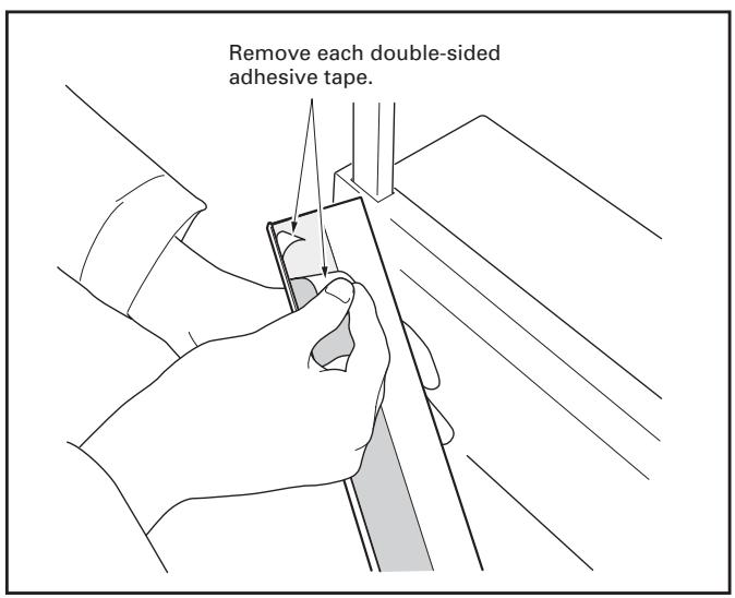
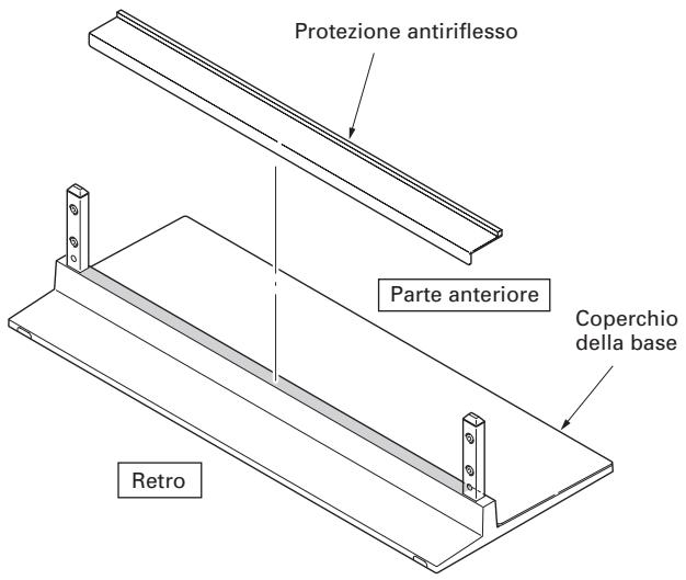
Attaching the Light-blocking Shield (PDK-TS30A only)
This part prevents reflection of the cables connected to the back of the plasma television on the base cover.
Note
Attach it after anchoring the base cover on a flat stable place.

Attachment Procedure
1 Remove the double-sided adhesive tape from the light-blocking shield.
2 While firmly holding the ends of the light-blocking shield, apply it with the double-sided adhesive tape.
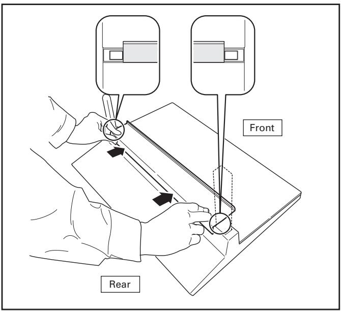
Note
- Be careful that the light-blocking shield does not catch on the pipe insertion holes.
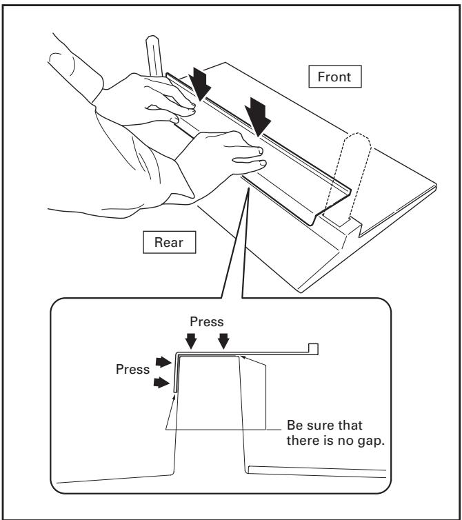
- Anchor it in place so that there are no gaps (See diagram at below). If there is a gap, the light-blocking shield may peel off.
3 Anchor it in place while pressing it down from above.
Attaching the Plasma Television

Caution
The weight of a plasma television is about 55.5kg (122.4 lbs), they have no depth, and are unstable. Therefore, at least two people must assemble and install them.
Note
- Be sure to install it on a flat stable location.
- Insert the screws in the holes vertically and do not tighten them with more force than necessary.
- Place a sheet or other material under the display to prevent scratches or damage to it.
- After manually turning the screw lightly two or three times, tighten it with a screw-driver.
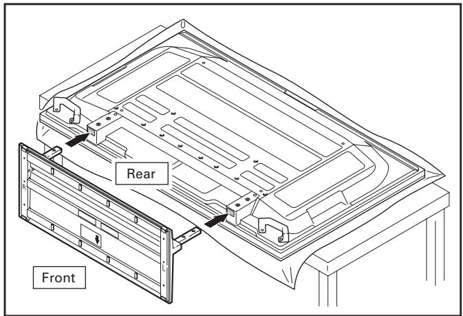
1 Attaching the plasma television to the stand.
Lay the plasma television down flat. Align the stand supports with the plasma television stand slots, and slowly insert the supports horizontally.
Please ensure that the stand supports do not come into contact with anything other than the plasma television stand slots. Contact with any other area may result in scratching or deformation of the display's rear side or terminals.
Note
When laying down the plasma television, be careful so as to not scratch or damage it.
2 Securing the plasma television with Installation screws ② (M6×20 mm: black).
Please tighten the screws with a Phillips screwdriver.
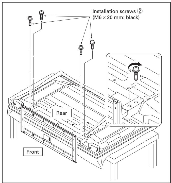
Note
Please stand the plasma television upright after installing the stand.
Installing the Product on a Rack etc.

Caution
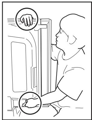
- When installing on a rack etc., please be sure that the plasma television is held by two or more people.
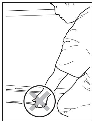
- Please do not hold the plasma television by the speakers or stand. Doing so may damage the product.
Hold the plasma television by its handles and from the top.
Do not hold the plasma television by the speakers.
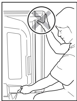
Do not hold the plasma television by the stand.
Preventing Equipment from Falling Over
- After installing the stand, be sure to take special care to ensure that the equipment will not fall over.
- Secure the plasma television to both the rack and the wall surface.
Stabilizing on a rack etc.
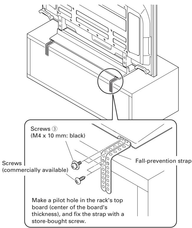
Fix the plasma television using the screws ③ (M4 × 10 mm: black) and fall-prevention straps as shown in the diagram. Fix the racks etc. using screws for sale on the market.
Note
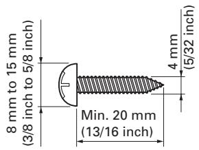
To stabilize the equipment on a table, use screws that have a nominal diameter of 4mm (5/32 inch) and that are at least 20mm (13/16 inch) long.
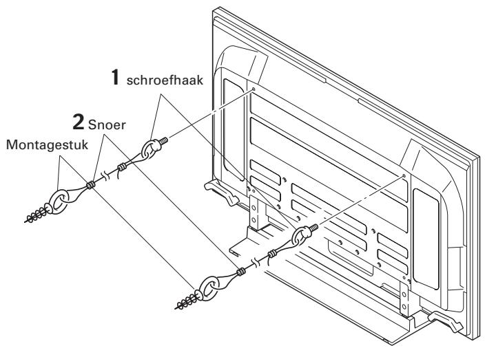
Using a wall for stabilization
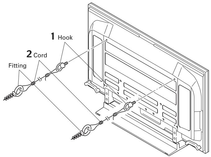
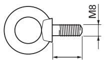
1 Attaching falling prevention bolts (hooks) to the plasma television.
2 Using strong cords to firmly stabilize it appropriately and firmly to a wall, pillar, or other sturdy element.
Perform this work in the same way on the left and right sides.
Note
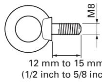
Use hooks, cords, and fittings that are available on the market.
Recommended hook:
Nominal diameter M8
Length 12 mm to 15 mm (1/2 inch to 5/8 inch)
Specifications
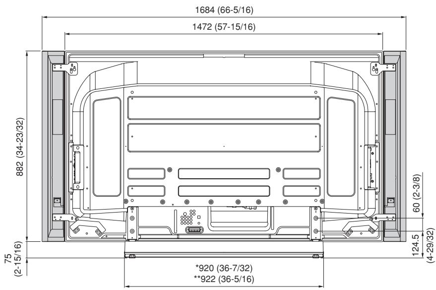
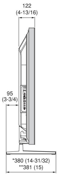
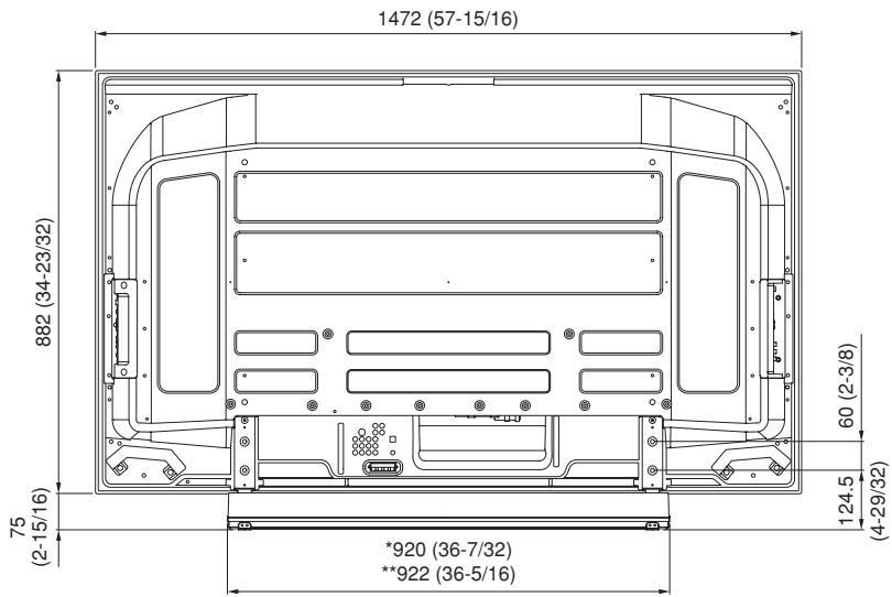
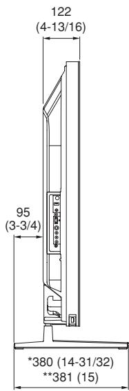
External dimensions:
PDK-TS30 920 mm (W) × 222.4 mm (H) × 380 mm (D) (36-7/32 in. (W) × 8-3/4 in. (H) × 14-31/32 in. (D))
PDK-TS30A 922 mm (W) × 222.4 mm (H) × 381 mm (D) (36-5/16 in. (W) × 8-3/4 in. (H) × 15 in. (D))
Weight:
PDK-TS30 5.7 kg (13.0 lbs)
PDK-TS30A 6.8 kg (15 lbs)
- The above specifications and exterior may be modified without prior notice to improve the product.
When the side speakers are installed
Unit: mm (inch)
- PDK-TS30 ** PDK-TS30A
Without speakers
Unit: mm (inch)
- PDK-TS30 ** PDK-TS30A
Published by Pioneer Corporation. Copyright © 2007 Pioneer Corporation. All rights reserved.

Ecran occultant × 1
(PDK-TS30A unquipment)
Procedure installation
Publication de Pioneer Corporation.
© 2007 Pioneer Corporation.
Fissatela工程技术 is a 1970 Italian film by the director, who was born in Italy. The main character of the film is a man who is working as a technician at a factory. He is married to his wife and he is also a father. His wife is an employee of the company.
Nominate diameter M8
Lenght 12mm tot 15mm
12 mm tot 15 mm
Technische gegevens
AFTER-SALES SERVICE FOR PIONEER PRODUCTS
Please contact the dealer or distributor from where you purchased the product for its after-sales service (including warranty conditions) or any other information. In case the necessary information is not available, please contact the Pioneer's subsidiaries (regional service headquarters) listed below:
PLEASE DO NOT SHIP YOUR PRODUCT TO THE COMPANIES at the addresses listed below for repair without advance contact, for these companies are not repair locations.
AMERICA
PIONEER ELECTRONICS (USA) INC.
CUSTOMER SUPPORT DIVISION
P.O. BOX 1760, LONG BEACH, CA 90801-1760, U.S.A.
CUSTOMER SERVICE HOTLINE : (800) 421-1625
EUROPE
PIONEER EUROPE NV
EUROPEAN SERVICE DIVISION
HAVEN 1087, KEETBERGLAAN 1, B-9120 MELSELE, BELGIUM
ASEAN
PIONEER ELECTRONICS ASIACENTRE PTE. LTD.
SERVICE DEPARTMENT
253, ALEXANDRA ROAD #04-01 SINGAPORE 159936
JAPAN AND OTHERS
PIONEER CORPORATION (HEAD OFFICE)
CUSTOMER SUPPORT CENTER
Printed on recycled paper.
Published by Pioneer Corporation.
Copyright © 2007 Pioneer Corporation.
All rights reserved.
Publication de Pioneer Corporation.
© 2007 Pioneer Corporation.
PIONEER ELECTRONICS (USA) INC.
P.O. BOX 1540, Long Beach, California 90801-1540, U.S.A. TEL: (800) 421-1404
PIONEER ELECTRONICS OF CANADA, INC.
300 Allstate Parkway, Markham, Ontario L3R 0P2, Canada TEL: 1-877-283-5901, 905-479-4411
PIONEER EUROPE NV
Haven 1087, Keetberglaan 1, B-9120 Melsele, Belgium TEL: 03/570.05.11
PIONEER ELECTRONICS ASIACENTRE PTE. LTD.
253 Alexandra Road, #04-01, Singapore 159936 TEL: 65-6472-7555
PIONEER ELECTRONICS AUSTRALIA PTY. LTD
178-184 Boundary Road, Braeside, Victoria 3195, Australia, TEL: (03) 9586-6300
PIONEER ELECTRONICS DE MEXICO S.A. DE C.V.
Blvd. Manuel Avila Camacho 138 10 piso Col.Lomas de Chapultepec, Mexico,D.F. 11000 TEL: 55-9178-4270
- Installation
- IMPORTANT NOTICE
- Contents
- CAUTION
- Cautions
- Installation Location
- Assembling and Installation
- Checking the Standard Accessories
- Assembling the Stand
- Assembly Procedure
- Note
- Attaching the Light-blocking Shield (PDK-TS30A only)
- Attachment Procedure
- Attaching the Plasma Television
- Attaching the plasma television to the stand.
- Securing the plasma television with Installation screws ② (M6×20 mm: black).
- Installing the Product on a Rack etc.
- Preventing Equipment from Falling Over
- Stabilizing on a rack etc.
- Using a wall for stabilization
- Specifications
- External dimensions:
- Weight:
- When the side speakers are installed
- Without speakers
- Procedure installation
- Technische gegevens
- AFTER-SALES SERVICE FOR PIONEER PRODUCTS
- AMERICA
- EUROPE
- ASEAN
- JAPAN AND OTHERS
Brand : PIONEER
Model : PDK-TS30
Category : Electronic device stand