
4112HS - Grinders MAKITA - Free user manual and instructions
Find the device manual for free 4112HS MAKITA in PDF.
| Product type | Concrete saw (angle grinder) |
| Brand | MAKITA |
| Model | 4112HS |
| Disc diameter | 305 mm |
| Max cutting capacity | 100 mm |
| No-load speed | 5000 min⁻¹ |
| Total length | 648 mm |
| Net weight | 10.3 kg |
| Power supply | 230 V ~ 50 Hz (single phase) |
| Safety class | Double insulation (Class II) |
| Disc type | Dry diamond disc |
| Depth adjustment | By wing bolt on depth guide |
| Disc guard | Adjustable approx. 80° (tightening nut) |
| Locking system | Lock lever for accidental start prevention and continuous operation |
| Shaft lock | Yes, for disc change |
| Vacuum cleaner connection | Yes (with optional connection elbow) |
| Carbon brush replacement | Automatic (insulator button); identical brushes |
| Sound pressure level | 103 dB(A) |
| Sound power level | 116 dB(A) |
| Vibration (acceleration) | ≤ 2.5 m/s² |
| Recommended use | Dry cutting of concrete, ferrous materials, pipes |
| Included accessories | Socket wrench 17, ring, dust cap, screwdriver |
Frequently Asked Questions - 4112HS MAKITA
User questions about 4112HS MAKITA
0 question about this device. Answer the ones you know or ask your own.
Ask a new question about this device
Download the instructions for your Grinders in PDF format for free! Find your manual 4112HS - MAKITA and take your electronic device back in hand. On this page are published all the documents necessary for the use of your device. 4112HS by MAKITA.
USER MANUAL 4112HS MAKITA
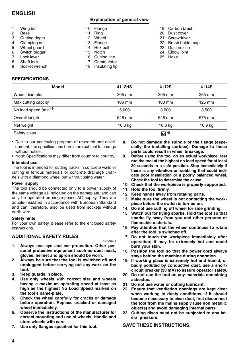
Explanation of general view
| 1 | Wing bolt | 10 | Flange | 19 | Carbon brush |
| 2 | Base | 11 | Ring | 20 | Dust cover |
| 3 | Cutting depth | 12 | Wheel | 21 | Screwdriver |
| 4 | Clamping nut | 13 | Flange | 22 | Brush holder cap |
| 5 | Wheel guard | 14 | Hex bolt | 23 | Dust nozzle |
| 6 | Switch trigger | 15 | Notch | 24 | Elbow joint |
| 7 | Lock lever | 16 | Cutting line | 25 | Hose |
| 8 | Shaft lock | 17 | Commutator | ||
| 9 | Socket wrench | 18 | Insulating tip |
SPECIFICATIONS
| Model | 4112HS | 4112S | 4114S |
| Wheel diameter | 305 mm | 305 mm | 355 mm |
| Max cutting capacity | 100 mm | 100 mm | 125 mm |
| No load speed (min-1) | 5,000 | 3,500 | 3,500 |
| Overall length | 648 mm | 648 mm | 675 mm |
| Net weight | 10.3 kg | 10.3 kg | 10.9 kg |
| Safety class | ☐/II | ||
- Due to our continuing program of research and development, the specifications herein are subject to change without notice.
Note: Specifications may differ from country to country.
Intended use
The tool is intended for cutting tracks in concrete walls or cutting in ferrous materials or concrete drainage channels with a diamond wheel but without using water.
Power supply
The tool should be connected only to a power supply of the same voltage as indicated on the nameplate, and can only be operated on single-phase AC supply. They are double-insulated in accordance with European Standard and can, therefore, also be used from sockets without earth wire.
Safety hints
For your own safety, please refer to the enclosed safety instructions.
ADDITIONAL SAFETY RULES
ENB064-1
- Always use eye and ear protection. Other personal protective equipment such as dust mask, gloves, helmet and apron should be worn.
- Always be sure that the tool is switched off and unplugged before carrying out any work on the tool.
- Keep guards in place.
- Use only wheels with correct size and wheels having a maximum operating speed at least as high as the highest No Load Speed marked on the tool's name-plate.
- Check the wheel carefully for cracks or damage before operation. Replace cracked or damaged wheel immediately.
- Observe the instructions of the manufacturer for correct mounting and use of wheels. Handle and store wheels with care.
-
Use only flanges specified for this tool.
-
Do not damage the spindle or the flange (especially the installing surface). Damage to these parts could result in wheel breakage.
- Before using the tool on an actual workpiece, test run the tool at the highest no load speed for at least 30 seconds in a safe position. Stop immediately if there is any vibration or wobbling that could indicate poor installation or a poorly balanced wheel. Check the tool to determine the cause.
- Check that the workpiece is properly supported.
- Hold the tool firmly.
- Keep hands away from rotating parts.
- Make sure the wheel is not contacting the workpiece before the switch is turned on.
- Do not use cutting off wheel for side grinding.
- Watch out for flying sparks. Hold the tool so that sparks fly away from you and other persons or flammable materials.
- Pay attention that the wheel continues to rotate after the tool is switched off.
- Do not touch the workpiece immediately after operation; it may be extremely hot and could burn your skin.
- Position the tool so that the power cord always stays behind the machine during operation.
- If working place is extremely hot and humid, or badly polluted by conductive dust, use a short-circuit breaker (30 mA) to assure operator safety.
- Do not use the tool on any materials containing asbestos.
- Do not use water or cutting lubricant.
- Ensure that ventilation openings are kept clear when working in dusty conditions. If it should become necessary to clear dust, first disconnect the tool from the mains supply (use non metallic objects) and avoid damaging internal parts.
- Cutting discs must not be subjected to any lateral pressure.
SAVE THESE INSTRUCTIONS.
FUNCTIONAL DESCRIPTION
CAUTION:
Always be sure that the tool is switched off and unplugged before adjusting or checking function on the tool.
Adjusting the depth of cut (Fig. 1)
Loosen the wing bolt on the depth guide and move the base up or down. At the desired depth of cut, secure the base by tightening the wing bolt.
Only in case you adjust the cutting depth to the maximum one, always be sure to do the depth adjustment after adjustment of the wheel guard.
Securing wheel guard (Fig. 2)
CAUTION:
- The wheel guard must be adjusted on the tool so that the closed side of the guard always points toward the operator.
The wheel guard can be adjusted about 80 degrees, after you loosen the clamping nut. Adjust to the desired angle, then secure the clamping nut.
Switch action (Fig. 3)
CAUTION:
- Before plugging in the tool, always check to see that the switch trigger actuates properly and returns to the "OFF" position when released.
For tool with the lock-on switch
To start the tool, simply pull the switch trigger. (A direction) Release the switch trigger to stop.
For continuous operation, pull the switch trigger (A direction) and then push in the lock lever. (B direction)
To stop the tool from the locked position, pull the switch trigger (A direction) fully, then release it.
For tool with the lock-off switch
To prevent the switch trigger from accidentally pulled, a lock lever is provided.
To start the tool, push in the lock lever (B direction) and then pull the switch trigger. (Adirection) Release the switch trigger to stop.
For tool with the lock on and lock-off switch
To prevent the switch trigger from accidentally pulled, a lock lever is provided.
To start the tool, push in the lock lever (B direction) and then pull the switch trigger. (A direction) Release the switch trigger to stop.
For continuous operation, push in the lock lever, (B direction) pull the switch trigger (A direction) and then push the lock lever (B direction) further in.
To stop the tool from the locked position, pull the switch trigger (A direction) fully, then release it.
ASSEMBLY
CAUTION:
Always be sure that the tool is switched off and unplugged before carrying out any work on the tool.
Installing or removing the wheel (Fig. 4 & 5)
To remove the wheel, depress the shaft lock to hold the shaft stationary, then loosen the hex bolt clockwise with the socket wrench.
To install a wheel, place flange with its partly elevated side facing the tool, and then place ring before installing a wheel onto the spindle (shaft) and another flange with partly elevated side facing outward.
Be sure to fully tighten the hex bolt counterclockwise after mounting the new wheel, or operation will be dangerous.
CAUTION:
- Use only the Makita wrench to install or remove the wheel.
OPERATION
CAUTION:
Be sure to pull the tool when cutting a workpiece.
- Use this tool for straight line cutting only. Cutting curves can cause stress cracks or fragmentation of the diamond wheel and abrasive cut-off wheel resulting in possible injury to persons in the vicinity.
After operation, always switch off the tool and wait until the wheel has come to a complete stop before putting the tool down. - When cutting concrete blocks, tiles or masonry materials, do not make a cut in depth more than 60~mm . When you need to cut a workpiece over 60~mm up to 100~mm , make more than two passes of cuts. The depth of the most efficient cut is about 40~mm .
Hold the tool firmly with both hands. First keep the wheel without making any contact with a workpiece to be cut. Then turn the tool on and wait until the wheel attains full speed.
The cut is made by pulling the tool toward you (not by pushing away from you). Align the notch on the base with your cutting line when performing a cut.
Switch off the tool in the position posed when finishing a cut. Raise the tool after the wheel comes to a complete stop. (Fig. 6)
MAINTENANCE
CAUTION:
Always be sure that the tool is switched off and unplugged before attempting to perform inspection or maintenance.
Dressing diamond wheel
If the cutting action of the diamond wheel begins to diminish, use an old discarded coarse grit bench grinder wheel or concrete block to dress the diamond wheel. To do this, tightly secure the bench grinder wheel or concrete block and cut in it.
Replacing carbon brushes (Fig. 7 & 8)
When the resin insulating tip inside the carbon brush is exposed to contact the commutator, it will automatically shut off the motor. When this occurs, both carbon brushes should be replaced. Keep the carbon brushes clean and free to slip in the holders. Both carbon brushes should be replaced at the same time. Use only identical carbon brushes.
Pick up an end of the dust cover slightly with hands so that brush hoder cap appears.
Use a screwdriver to remove the brush holder caps. Take out the worn carbon brushes, insert the new ones and secure the brush holder caps.
To maintain product SAFETY and RELIABILITY, repairs, any other maintenance or adjustment should be performed by Makita Authorized Service Centers, always using Makita replacement parts.
ACCESSIONS
CAUTION:
- These accessories or attachments are recommended for use with your Makita tool specified in this manual. The use of any other accessories or attachments might present a risk of injury to persons. Only use accessory or attachment for its stated purpose.
If you need any assistance for more details regarding these accessories, ask your local Makita service center.
- Diamond wheels (Dry type)
- Abrasive cut-off wheels
- Socket wrench 17
- Safety goggle
Ring 20
Elbow joint
Connecting to vacuum cleaner (Fig. 9)
When you wish to perform cleaner operation, connect a vacuum cleaner to your tool. Connect a hose of vacuum cleaner to the dust nozzle via an elbow joint (accessory).
Descriptif
Tia epyaaleioe tov biakottnn aataqalions
Tia va eunodioTei To tuxaio TpaBnyuma TnOakovdAicaioknt, evac moXloC aoPdAionc exE npoBaeoi
Ia va EaKivnEo To EpyAeio, OnpxTe MeoA too
OxloAo aaoAianC (IaeUtheta B) KAI eTa TpaBnte
Tyn OkavdaN diakontn. (IaeUthetavAn A)
EeUepwTe Tnv 0avdaa n daokntn yia va oatajnoi.
Iα εpyaεio με δiaKoTTn aσφαλiσns KαI aTασφαλiσns
Tia va eunnoiotei To tuxaio TpaBnyuma TnOakovdAanC diakontn, evac moXloC aoPdAionc exTe npoBaeoi
Tva va EekivnEto EpyaLio, OnpxTe MeoA tov loxAo aocAiaIc (DleUtheta B) kal eTa tpaBnte Tyn okaVdAn diakontn. (DleUthetavAn A)
EeUepwTe Tnv 0avdaa n daokntn yia va oatajoi.
Ia ouvexn leitoupyia, onpwxte meoTo moxlo ooaaiionc. (AieuuvonB) npahtxTe nTv okaovdAn diakontn (AieuuvonA) kai mt aonpwxTe tov moxlo ooaaiionc (AieuuvonB) nio eoA.
Ia va otauamanei to ypaaleio ano tyn teon aoafalionc, taepxte npnpoc nyn okanadn diakontn (Aieuuvon A), eTa eueoepwote nyn.
SYNAPMOANOFHEH
PPOEOXH:
EC-DECLARATION OF CONFORMITY
We declare under our sole responsibility that this product is in compliance with the following standards of standardized documents,
EN50144, EN55014, EN61000
in accordance with Council Directives, 89/336/EEC and 98/37/EC.
FRANÇAISE
DECLARATION DE CONFORMITE CE
Michigan Drive, Tongwell, Milton Keynes, Bucks MK15 8JD, ENGLAND
Responsible manufacturer:
Fabricant responsible :
Fabricante responsible:
Makita Corporation Anjo Aichi Japan
PORTUGUES
EU-DEKLARATION OM KONFORMITET
Michigan Drive, Tongwell, Milton Keynes, Bucks MK15 8JD, ENGLAND
Fabricante responsavel:
Ansvarlig fabrikant:
For European countries only
Noise and Vibration of Model 4112S/4112HS
The typical A-weighted noise levels are
sound pressure level: 103 dB (A)
sound power level: 116 dB (A)
- Wear ear protection. -
The typical weighted root mean square acceleration value is not more than 2.5m / s^2
These values have been obtained according to EN50144.
FRANÇAISE
Móvo yia xwpc ts Eupwnns
OpuoKai Kpaadaoos
For European countries only
Noise and Vibration of Model 4114S
The typical A-weighted noise levels are
sound pressure level: 99 dB (A)
sound power level: 112 dB (A)
- Wear ear protection. -
The typical weighted root mean square acceleration value is not more than 2.5m / s^2
These values have been obtained according to EN50144.
FRANÇAISE
Móvo yia xwpeTc Eupwnnc
Oópuβoc kαi kpaδaμoç tou μovtělou 4114S
OtuikcA-μeTpouEvEcEVTaoeic hou evai


- Intended use
- Power supply
- Safety hints
- ADDITIONAL SAFETY RULES
- FUNCTIONAL DESCRIPTION
- CAUTION:
- Adjusting the depth of cut (Fig. 1)
- Securing wheel guard (Fig. 2)
- Switch action (Fig. 3)
- For tool with the lock-on switch
- For tool with the lock-off switch
- For tool with the lock on and lock-off switch
- ASSEMBLY
- Installing or removing the wheel (Fig. 4 & 5)
- OPERATION
- MAINTENANCE
- Dressing diamond wheel
- Replacing carbon brushes (Fig. 7 & 8)
- ACCESSIONS
- Connecting to vacuum cleaner (Fig. 9)
- Descriptif
- Tia epyaaleioe tov biakottnn aataqalions
- Iα εpyaεio με δiaKoTTn aσφαλiσns KαI aTασφαλiσns
- SYNAPMOANOFHEH
- PPOEOXH:
- EC-DECLARATION OF CONFORMITY
- FRANÇAISE
- DECLARATION DE CONFORMITE CE
- PORTUGUES
- EU-DEKLARATION OM KONFORMITET
- For European countries only
- Noise and Vibration of Model 4112S/4112HS
- Noise and Vibration of Model 4114S
- Móvo yia xwpeTc Eupwnnc
- Oópuβoc kαi kpaδaμoç tou μovtělou 4114S
Brand : MAKITA
Model : 4112HS
Category : Grinders