9560CV - Grinders MAKITA - Free user manual and instructions
Find the device manual for free 9560CV MAKITA in PDF.

| Brand | Makita |
| Model | 9560CV |
| Product type | Angle grinder |
| Wheel diameter | 100 mm |
| Arbor thread | M10 |
| No-load speed | 11,000 rpm |
| Variable speed control | Yes, adjustable from 2,800 to 11,000 rpm (5 levels) |
| Overall length | 289 mm |
| Net weight | 1.7 kg |
| Power supply | Single-phase, double insulation, voltage per nameplate |
| Soft start function | Yes |
| Overload protection | Yes, automatic shut-off |
| Shaft lock | Yes, for wheel change |
| Side handle | Yes, mountable on either side |
| Protection guard | Yes, adjustable |
| Sound pressure level | 83 dB(A) |
| Sound power level | Up to 85 dB(A) |
| Vibration (weighted acceleration) | 4 m/s² |
| Maintenance | Clean ventilation openings regularly |
| Repairability | Have repairs carried out by an authorized Makita service center |
Frequently Asked Questions - 9560CV MAKITA
User questions about 9560CV MAKITA
0 question about this device. Answer the ones you know or ask your own.
Ask a new question about this device
Download the instructions for your Grinders in PDF format for free! Find your manual 9560CV - MAKITA and take your electronic device back in hand. On this page are published all the documents necessary for the use of your device. 9560CV by MAKITA.
USER MANUAL 9560CV MAKITA
100 mm 9560C/9560CV/9563C/9563CV
115 mm 9561C/9561CV/9564C/9564CV
125 mm 9562C/9562CV/9565C/9565CV

1
2
3
4
5
6
7
8
9
10
Symbols
The following show the symbols used for the tool. Be sure that you understand their meaning before use
Symboles
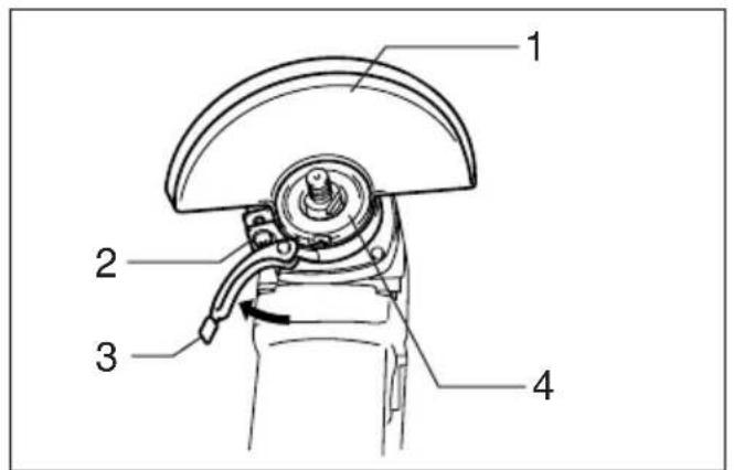
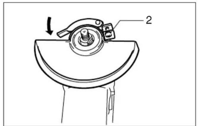
1 Wheel cover
2 Screw
3 Lever
4 Bearing box
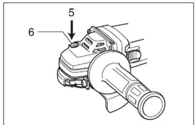
5 Press
6 Shaft lock
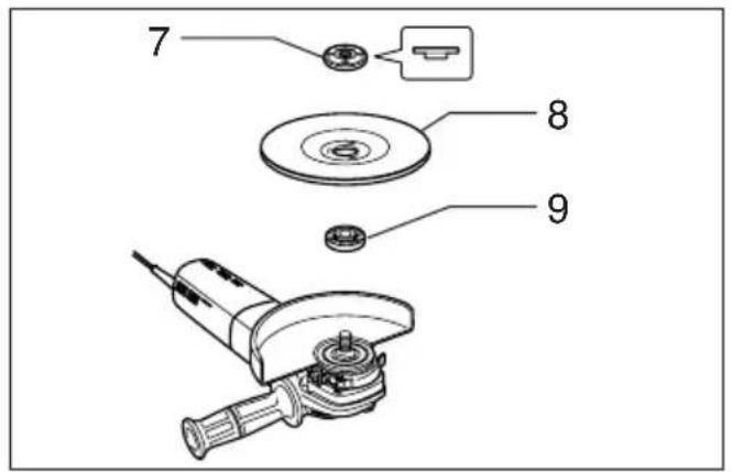
7 Lock nut
8 Depressed center wheel
9 Inner flange
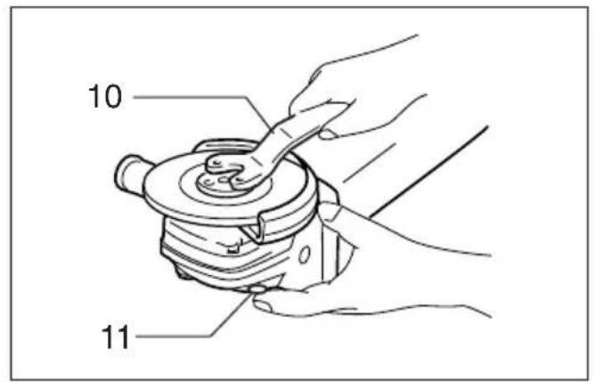
10 Lock nut wrench
11 Shaft lock
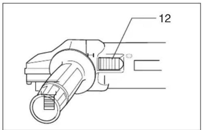
12 Switch lever
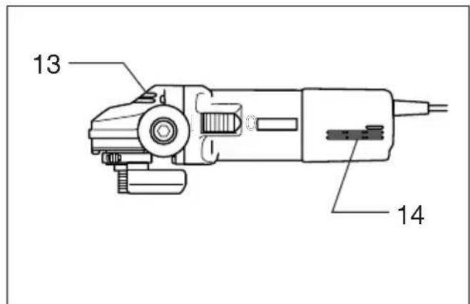
13 Exhaust vent
14 Inhalation vent
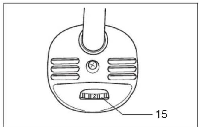
15 Speed adjusting dial
SPECIFICATIONS
| Depressed center wheel diameter/Spindle thread | 100 mm M10 | 9560C 95 | 63C 9560 | CV 9563CV | |
| 115 mm M14 | 9561C 95 | 64C 9561 | CV 9564CV | ||
| 125 mm M14 | 9562C 95 | 65C 9562 | CV 9565CV | ||
| No load speed (mih) 11,000 11,000 2,800 - 1 | 1,000 2,8 | 00 - 11,000 | |||
| Overall length | 289 mm | 299 mm | 289 mm | 299 mm | |
| Net weight | 1.7 kg | 1.8 kg | 1.7 kg | 1.8 kg | |
- Due to our continuing program of research and development, the specifications herein are subject to change without notice.
Note: Specifications may differ from country to country.
Power supply
The machine should be connected only to a power supply of the same voltage as indicated on the nameplate, and can only be operated on single-phase
AC supply. They are double-insulated in accordance with European Standard and can, therefore, also be used from sockets without earth wire.
Safety hints
For your own safety, please refer to the enclosed safety instructions.
ADDITIONAL SAFETY RULES
ENB031-4
- Always use eye and ear protection. Other personal protective equipment such as dust mask, gloves, helmet and apron should be worn when necessary. If in doubt, wear the protective equipment.
- Always be sure that the tool is switched off and unplugged before carrying out any work on the tool.
- Keep guards in place.
- Use only wheels with correct size and wheels having a maximum operating speed at least as high as the highest No Load Speed marked on the tool's nameplate.When using depressed center wheels, be sure to use only fiberglass reinforced wheels.
- Check the wheel carefully for cracks or damage before operation. Replace cracked or damaged wheel immediately.
- Observe the instructions of the manufacturer for correct mounting and use of wheels. Handle and store wheels with care.
-
Do not use separate reducing bushings or adaptors to adapt large hole abrasive wheels.
-
Use only flanges specified for this tool.
- Do not damage the spindle, the flange (especially the installing surface) or the lock nut. Damage to these parts could result in wheel breakage.
- For tools intended to be fitted with threaded hole wheel, ensure that the thread in the wheel is long enough to accept the spindle length.
- Before using the tool on an actual workpiece, test run the tool at the highest no load speed for at least 30 seconds in a safe position. Stop immediately if there is any vibration or wobbling that could indicate poor installation or a poorly balanced wheel. Check the tool to determine the cause.
- Check that the workpiece is properly supported.
13.Hold the tool firmly. - Keep hands away from rotating parts.
- Make sure the wheel is not contacting the workpiece before the switch is turned on.
16.Use the specified surface of the wheel to perform the grinding. - Do not use cutting off wheel for side grinding.
- Watch out for flying sparks. Hold the tool so that sparks fly away from you and other persons or flammable materials.
- Pay attention that the wheel continues to rotate after the tool is switched off.
- Do not touch the workpiece immediately after operation; it may be extremely hot and could burn your skin.
- Position the tool so that the power cord always stays behind the tool during operation.
- If working place is extremely hot and humid, or badly polluted by conductive dust, use a short-circuit breaker (30 mA) to assure operator safety.
- Do not use the tool on any materials containing asbestos.
-
Do not use water or grinding lubricant.
-
Ensure that ventilation openings are kept cleSwitch action (Fig. 7) when working in dusty conditions. If it should:
become necessary to clear dust, first disconnect the tool from the main supply (use non metallic objects) and avoid damaging internal parts.
SAVE THESE INSTRUCTIONS.
OPERATING INSTRUCTIONS
Installing wheel guard (Fig. 1 & 2)
Important:
Always be sure that the tool is switched off and unplugged before installing or removing the wheel guard.
Pull the lever in the direction of the arrow after loosening the screw.
- Install the wheel cover on the bearing box by adjusting the convex of the wheel cover to the concave edge of the bearing box.
Turn the wheel cover by 180 degrees. Fasten it with the screw after pulling lever in the direction of the arrow for the working purpose, the setting angle of wheel cover can be adjusted with the lever.
Removing wheel cover
Follow the installation procedure in reverse to remove the wheel cover.
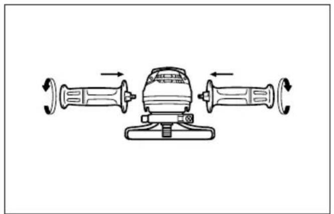
Installing side grip (auxiliary handle) (Fig. 3)
Important:
Always be sure that the tool is switched off and unplugged before installing or removing the side grip
Always install the side grip on the tool securely before operation. The side grip can be installed on either side of the tool, whichever is convenient and keeps the guard properly positioned. Always hold the tool's switch handle and the side grip firmly with both hands during operation.
Shaft lock (Fig. 4)
Press the shaft lock to prevent spindle rotation when installing or removing accessories.
CAUTION:
Never actuate the shaft lock when the spindle is moving. The tool may be damaged.
Installing or removing depressed center wheel (Fig. 5 & 6)
Important:
Always be sure that the tool is switched off and unplugged before installing or removing the wheel.
Mount the inner flange onto the spindle. Fit the wheelsoft start feature
on over the inner flange and screw the lock nut onto safety and soft start because of suppressed starting the spindle.
To tighten the lock nut, press the shaft lock firmly 0 Overload protector
that the spindle cannot revolve, then use the lock nutWhen the tool would be employed over the admisswrench and securely tighten clockwise. sible load, it will stop automatically to protect the
To remove the wheel, follow the installation procedure motor and wheel. When the load will come to the in reverse. admissible level again, the tool can be started automatically.
Before plugging in the tool, always check to see that the switch actuates properly and returns to the "OFF" position when the side of the switch lever is depressed.
To start the tool, slide the switch lever to "T" position. For continuous operation, depress the front of the switch lever and then slide to "T" position as above. The switch is locked on the position for continuous operation.
To stop the tool from the locked position, slide the switch lever to "O"position with depressing the rear of the switch lever.
Speed adjusting dial (For model 9560CV, 9561CV, 9562CV, 9563CV, 9564CV, 9565CV) (Fig. 8)
The rotating speed can be changed by turning the speed adjusting dial to a given number setting from 1 to 5.
Higher speed is obtained when the dial is turned in the direction of number 5. And lower speed is obtained when it is turned in the direction of number 1.
Refer to the table below for the relationship between the number settings on the dial and the approximate rotating speed.
| Number min | -1(R.P.M.) |
| 1 | 2,800 |
| 2 | 4,000 |
| 3 | 6,500 |
| 4 | 9,000 |
| 5 | 11,000 |
CAUTION:
- If the tool is operated continuously at low speeds for a long time, the motor will get overloaded and then heated up.
The speed adjusting dial can be turned only as far as 5 and back to 1. Do not force it past 5 or 1, or the speed adjusting function may no longer work.
The tools equipped with electronic function are easy to operate because of the following features.
- Constant speed control
Electronic speed control for obtaining constant speed.
Possible to get fine finish, because the rotating speed is kept constantly even under the loaded condition.
seeSoft start features
on over the inner flange and screw the lock nut onto safety and soft start because of suppressed starting the spindle.
into safety and soft start because of suppressed starting shock.
$Overload protector
nutWhen the tool would be employed over the admis
sible load, it will stop automatically to protect the motor and wheel. When the load will come to the admissible level again, the tool can be started automatically.
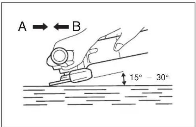
Operation (Fig. 9)
MAINTENANCE
CAUTION:
CAUTION:
After operation, always switch off the tool and wait Always be sure that the tool is switched off and until the wheel has come to a complete stop before unplugged before carrying out any work on the tool. putting the tool down. Repair and maintenance (Fig. 10)
Hold the tool firmly with both hands. Turn the tool and then apply the wheel or disc to the workpiece. In general, keep the edge of the wheel or disc at a angle of about 15^ - 30^ to the workpiece surface. During the break-in period with a new wheel, do not work the tool in the B direction or it will cut into the workpiece. Once the edge of the wheel has been rounded off by use, the wheel may be worked in both A and B directions.
Repair and maintenance (Fig. 10)
The tool and its opening vents for cooling air have to be always kept clean. When the foreign matters clog each parts, they have to be taken off.
WARNING:
- It should never be necessary to force the tool. The weight of the tool applies adequate pressure. Forcing and excessive pressure could cause dangerous wheel breakage.
- Continued use of a worn-out wheel may result in wheel explosion and serious personal injury.
Træk armen i pilens retning after at have Iøsnet skruen.
EC-DECLARATION OF CONFORMITY
The undersigned, Yasuhiko Kanzaki, authorized by Makita Corporation, 3-11-8 Sumiyoshi-Cho, Anjo, Aichi 446-8502 Japan declares that this product
(Serlal No.: series production)
manufactured by Makita Corporation in Japan is in compliance with the following standards or standardized documents,
HD400, EN50144, EN55014, EN61000
in accordance with Council Directives, 73/23/EEC, 89/336/EEC and 98/37/EC.
ITALIANO
HD400, EN50144, EN55014, EN61000.
ESPANOL
Michigan Drive, Tongwell, Milton Keynes,
Bucks MK15 8JD, ENGLAND
PORTUGUES
de accordo com as directivas 73/23/CEE, 89/336/CEE e 98/37/CE do Conselho.
DANSK
EU-DEKLARATION OM KONFORMITET
Undertegnede, Yasuhiko Kanzaki, med fuldmagt fra Maki Corporation, 3-11-8 Sumiyoshi-Cho, Anjo, Aichi 446-8502 Japan, erklær hermed, at dette produit
HD400. EN50144, EN55014, EN61000.
i samsvar med Rads-direktivene, 73/23/EEC, 89/336/EEC og 98/37/EC.
SVENSKA
EG-DEKLARATION OM ÖVERENSSTÄMMELSE
Undertechnad, Yasuhiko Kanzaki, auktoriserad av Makita Corporation, 3-11-8 Sumiyoshi-Cho, Anjo, Aichi 446-8502 Japan deklarerar attenna Produkt
(serienummer: sérieproduktion)
tillverkad av Makita Corporation i Japan, uppfyller kraven
foljande standard aller standardiserade dokument, HD400, EN50144, EN55014, EN61000
(AuEwAp: npaywyn oεipac)
kataokεuaαμεvo ano tny Etaipεia Makita otnv
lanovia, piokei a ooupwvia u ta akoloutheta npotuna n tunooineva eyypapa,
HD400, EN50144, EN55014, EN61000
ouφwva με TIC Oδnyieç tou Σuμβouλiou, 73/23/EEC, 89/336/EEC ka 98/37/KE.
Yasuhiko KanzakiCE 2000

Director Direktor
Direktor Johtaja
Direktor
MAKITA INTERNATIONAL EUROPE LTD.
Michigan Drive, Tongwell, Milton Keynes, Bucks MK15 8JD, ENGLAND
ENGLISH
Noise and Vibration of Model 9560C/9560CV/9561C/9561CV/9562C/9562CV
The typical A-weighted sound pressure level is 83 dB The noise level under working may exceed 85 dB (A).
- Wear ear protection.
The typical weighted root mean square acceleration valueO valor medio da aceleracao é 4 m/s is 4m / s
PORTUGUES
Noise and Vibration of Model 9563C/9563CV/9564C/9564CV/9565C/9565CV
The typical A-weighted sound pressure level is 83 dB The noise level under working may exceed 85 dB (A). -Wear ear protection.
The typical weighted root mean square acceleration value is 5m / s
FRANÇAISE
9563C/9563CV/9564C/9564CV/9565C/9565CV
9563C/9563CV/9564C/9564CV/9565C/9565CV
9563C/9563CV/9564C/9564CV/9565C/9565CV
9563C/9563CV/9564C/9564CV/9565C/9565CV
9563C/9563CV/9564C/9564CV/9565C/9565CV
Den typiska-A-vagda Ijudtrycksnivan ar 83 dB (A).
9563C/9563CV/9564C/9564CV/9565C/9565CV
Mallin 9563C/9563CV/9564C/9564CV/
9563C/9563CV/9564C/9564CV/9565C/9565CV
AHTurikn A-μετρομενn nxtikn πieon εiva83dB(A). H Evtaon nXou uno ouvθkec εpyaiaac μnpei va μeβεi ta 85 dB (A).
-Opatae wtoaonidc.
H tuniak aia tnc mepouevnc piac tou eou Tepayovou nC enitaxuvon cival 5 m/s2.
Makita Corporation
Anjo, Aichi, Japan
Made in Japan
884311C996